ECU JEEP WRANGLER UNLIMITED 2019 Owner handbook (in English)
[x] Cancel search | Manufacturer: JEEP, Model Year: 2019, Model line: WRANGLER UNLIMITED, Model: JEEP WRANGLER UNLIMITED 2019Pages: 348, PDF Size: 6.5 MB
Page 141 of 348
WARNING!
• NEVER place any objects under the floor
mat (e.g., towels, keys, etc.). These ob-
jects could change the position of the
floor mat and may cause interference
with the accelerator, brake, or clutch
pedals.
• If the vehicle carpet has been removed
and re-installed, always properly attach
carpet to the floor and check the floor
mat fasteners are secure to the vehicle
carpet. Fully depress each pedal to
check for interference with the accelera-
tor, brake, or clutch pedals then re-
install the floor mats.
• It is recommended to only use mild soap
and water to clean your floor mats. After
cleaning, always check your floor mat
WARNING!
has been properly installed and is se-
cured to your vehicle using the floor mat
fasteners by lightly pulling mat.
Periodic Safety Checks You Should Make
Outside The Vehicle
Tires
Examine tires for excessive tread wear and
uneven wear patterns. Check for stones,
nails, glass, or other objects lodged in the
tread or sidewall. Inspect the tread for cuts
and cracks. Inspect sidewalls for cuts,
cracks, and bulges. Check the wheel nuts for
tightness. Check the tires (including spare)
for proper cold inflation pressure.
Lights
Have someone observe the operation of brake
lights and exterior lights while you work the
controls. Check turn signal and high beam
indicator lights on the instrument panel.
Door Latches
Check for proper closing, latching, and lock-
ing.
Fluid Leaks
Check area under the vehicle after overnight
parking for fuel, coolant, oil, or other fluid
leaks. Also, if gasoline fumes are detected or
if fuel, or brake fluid leaks are suspected. The
cause should be located and corrected imme-
diately.
139
Page 175 of 348
9. Repeat steps seven and eight with the
transmission in DRIVE.
10. Turn the engine OFF and leave the igni-
tion in the unlocked ACC position.
11. Firmly apply the parking brake.
12. Shift the transmission into PARK (NOT
in NEUTRAL).
CAUTION!
Damage to the transmission may occur if
the transmission is shifted into PARK with
the transfer case in NEUTRAL (N) and the
engine running. With the transfer case in
NEUTRAL (N) ensure that the engine is
OFF before shifting the transmission into
PARK.13. Attach the vehicle to the tow vehicle
using a suitable tow bar.
14. Release the parking brake.
15. Disconnect the negative battery cable,
and secure it away from the negative
battery post.
Shifting Out of NEUTRAL (N)
Use the following procedure to prepare your
vehicle for normal usage.
1. Bring the vehicle to a complete stop, leav-
ing it connected to the tow vehicle.
2. Firmly apply the parking brake.
3. Reconnect the negative battery cable.
4. Start the engine.
5. Press and hold the brake pedal.
6. Shift the transmission into NEUTRAL.7. Turn the engine OFF.
8. Shift the transfer case lever to the desired
position.
NOTE:
When shifting the transfer case out of
NEUTRAL (N), the engine should remain
OFF to avoid gear clash.
9. Shift the transmission into PARK.
10. Release the brake pedal.
11. Disconnect vehicle from the tow vehicle.
12. Start the engine.
13. Press and hold the brake pedal.
14. Release the parking brake.
15. Shift the transmission into gear, release
the brake pedal, and check that the
vehicle operates normally.
173
Page 184 of 348
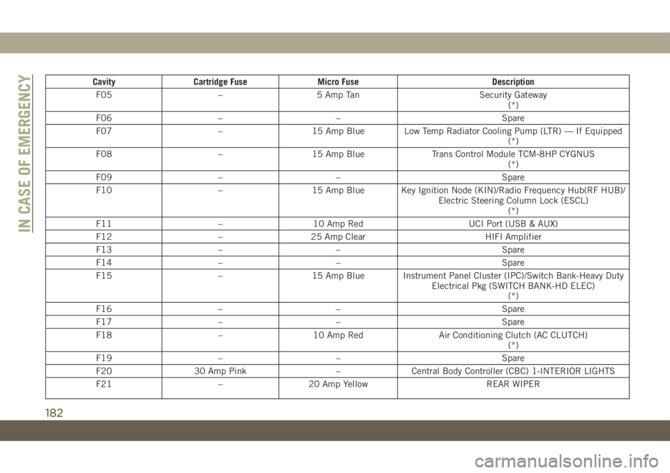
Cavity Cartridge Fuse Micro Fuse Description
F05 – 5 Amp Tan Security Gateway
(*)
F06 – – Spare
F07 – 15 Amp Blue Low Temp Radiator Cooling Pump (LTR) — If Equipped
(*)
F08 – 15 Amp Blue Trans Control Module TCM-8HP CYGNUS
(*)
F09 – – Spare
F10 – 15 Amp Blue Key Ignition Node (KIN)/Radio Frequency Hub(RF HUB)/
Electric Steering Column Lock (ESCL)
(*)
F11 – 10 Amp Red UCI Port (USB & AUX)
F12 – 25 Amp Clear HIFI Amplifier
F13 – – Spare
F14 – – Spare
F15 – 15 Amp Blue Instrument Panel Cluster (IPC)/Switch Bank-Heavy Duty
Electrical Pkg (SWITCH BANK-HD ELEC)
(*)
F16 – – Spare
F17 – – Spare
F18 – 10 Amp Red Air Conditioning Clutch (AC CLUTCH)
(*)
F19 – – Spare
F20 30 Amp Pink – Central Body Controller (CBC) 1-INTERIOR LIGHTS
F21 – 20 Amp Yellow REAR WIPER
IN CASE OF EMERGENCY
182
Page 186 of 348
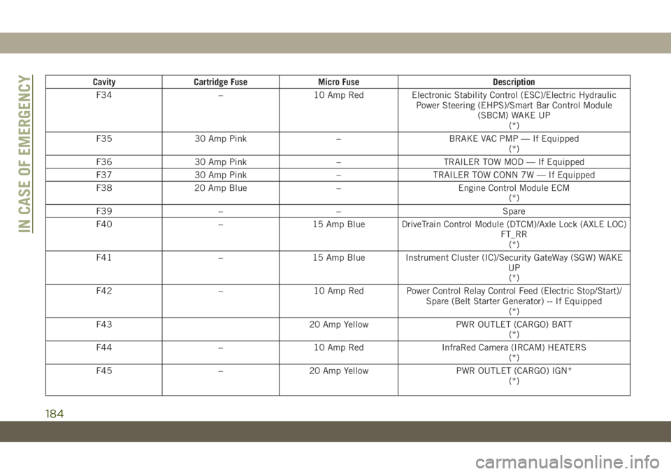
Cavity Cartridge Fuse Micro Fuse Description
F34 – 10 Amp Red Electronic Stability Control (ESC)/Electric Hydraulic
Power Steering (EHPS)/Smart Bar Control Module
(SBCM) WAKE UP
(*)
F35 30 Amp Pink – BRAKE VAC PMP — If Equipped
(*)
F36 30 Amp Pink – TRAILER TOW MOD — If Equipped
F37 30 Amp Pink – TRAILER TOW CONN 7W — If Equipped
F38 20 Amp Blue – Engine Control Module ECM
(*)
F39 – – Spare
F40 – 15 Amp Blue DriveTrain Control Module (DTCM)/Axle Lock (AXLE LOC)
FT_RR
(*)
F41 – 15 Amp Blue Instrument Cluster (IC)/Security GateWay (SGW) WAKE
UP
(*)
F42 – 10 Amp Red Power Control Relay Control Feed (Electric Stop/Start)/
Spare (Belt Starter Generator) -- If Equipped
(*)
F43 20 Amp Yellow PWR OUTLET (CARGO) BATT
(*)
F44 – 10 Amp Red InfraRed Camera (IRCAM) HEATERS
(*)
F45 – 20 Amp Yellow PWR OUTLET (CARGO) IGN*
(*)
IN CASE OF EMERGENCY
184
Page 190 of 348
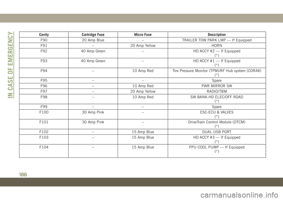
Cavity Cartridge Fuse Micro Fuse Description
F90 20 Amp Blue – TRAILER TOW PARK LMP — If Equipped
F91 – 20 Amp Yellow HORN
F92 40 Amp Green – HD ACCY #2 — If Equipped
(*)
F93 40 Amp Green – HD ACCY #1 — If Equipped
(*)
F94 – 10 Amp Red Tire Pressure Monitor (TPM)/RF Hub system (CORAX)
(*)
F95 – – Spare
F96 – 10 Amp Red PWR MIRROR SW
F97 – 20 Amp Yellow RADIO/TBM
F98 – 10 Amp Red SW BANK-HD ELEC/OFF ROAD
(*)
F99 – – Spare
F100 30 Amp Pink – ESC-ECU & VALVES
(*)
F101 30 Amp Pink – DriveTrain Control Module (DTCM)
(*)
F102 – 15 Amp Blue DUAL USB PORT
F103 – 15 Amp Blue HD ACCY #3 — If Equipped
(*)
F104 – 15 Amp Blue PPU COOL PUMP — If Equipped
(*)
IN CASE OF EMERGENCY
188
Page 192 of 348
WARNING!
• Being under a jacked-up vehicle is dan-
gerous. The vehicle could slip off the
jack and fall on you. You could be
crushed. Never put any part of your body
under a vehicle that is on a jack. If you
need to get under a raised vehicle, take
it to a service center where it can be
raised on a lift.
• Never start or run the engine while the
vehicle is on a jack.
• The jack is designed to be used as a tool
for changing tires only. The jack should
not be used to lift the vehicle for service
purposes. The vehicle should be jacked
on a firm level surface only. Avoid ice or
slippery areas.
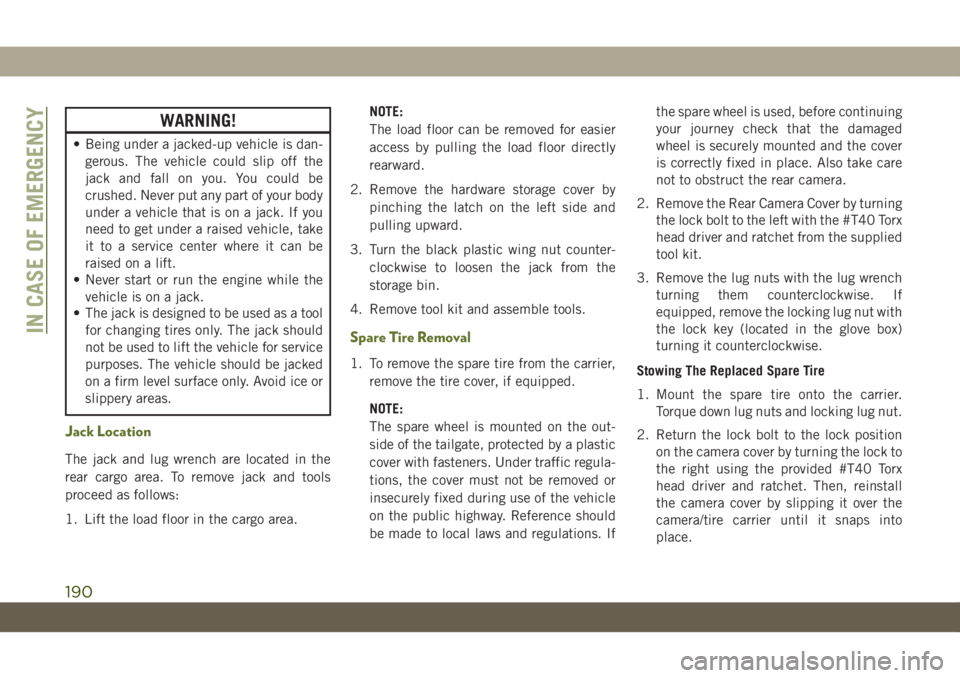
Jack Location
The jack and lug wrench are located in the
rear cargo area. To remove jack and tools
proceed as follows:
1. Lift the load floor in the cargo area.NOTE:
The load floor can be removed for easier
access by pulling the load floor directly
rearward.
2. Remove the hardware storage cover by
pinching the latch on the left side and
pulling upward.
3. Turn the black plastic wing nut counter-
clockwise to loosen the jack from the
storage bin.
4. Remove tool kit and assemble tools.
Spare Tire Removal
1. To remove the spare tire from the carrier,
remove the tire cover, if equipped.
NOTE:
The spare wheel is mounted on the out-
side of the tailgate, protected by a plastic
cover with fasteners. Under traffic regula-
tions, the cover must not be removed or
insecurely fixed during use of the vehicle
on the public highway. Reference should
be made to local laws and regulations. Ifthe spare wheel is used, before continuing
your journey check that the damaged
wheel is securely mounted and the cover
is correctly fixed in place. Also take care
not to obstruct the rear camera.
2. Remove the Rear Camera Cover by turning
the lock bolt to the left with the #T40 Torx
head driver and ratchet from the supplied
tool kit.
3. Remove the lug nuts with the lug wrench
turning them counterclockwise. If
equipped, remove the locking lug nut with
the lock key (located in the glove box)
turning it counterclockwise.
Stowing The Replaced Spare Tire
1. Mount the spare tire onto the carrier.
Torque down lug nuts and locking lug nut.
2. Return the lock bolt to the lock position
on the camera cover by turning the lock to
the right using the provided #T40 Torx
head driver and ratchet. Then, reinstall
the camera cover by slipping it over the
camera/tire carrier until it snaps into
place.
IN CASE OF EMERGENCY
190
Page 194 of 348
WARNING!
• If working on or near a roadway, be
extremely careful of motor traffic.
• To assure that spare tires, flat or in-
flated, are securely stowed, spares must
be stowed with the valve stem facing the
ground.
CAUTION!
Do not attempt to raise the vehicle by
jacking on locations other than those indi-
cated.
1. Remove the spare tire, jack and tools from
the stored location.
2. Loosen (but do not remove) the wheel lug
nuts by turning them to the left one turn
while the wheel is still on the ground.
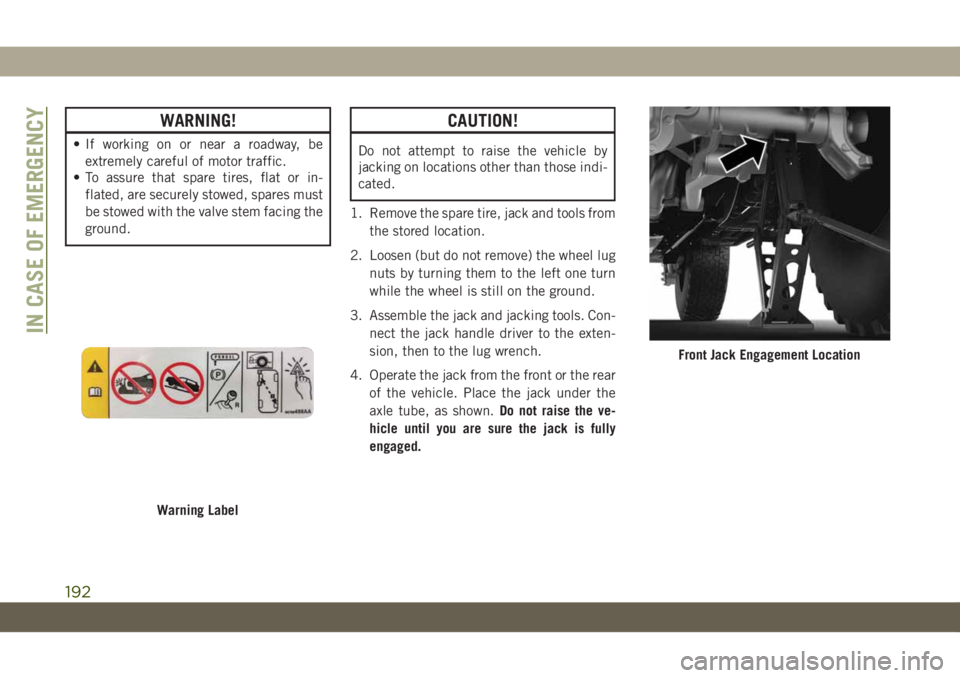
3. Assemble the jack and jacking tools. Con-
nect the jack handle driver to the exten-
sion, then to the lug wrench.
4. Operate the jack from the front or the rear
of the vehicle. Place the jack under the
axle tube, as shown.Do not raise the ve-
hicle until you are sure the jack is fully
engaged.
Warning Label
Front Jack Engagement Location
IN CASE OF EMERGENCY
192
Page 195 of 348
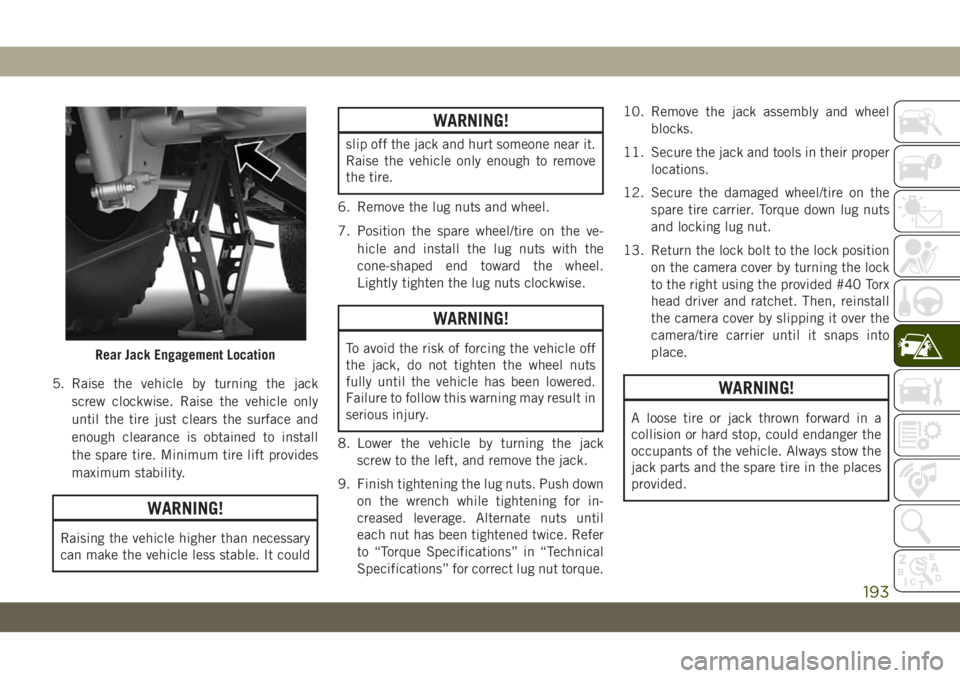
5. Raise the vehicle by turning the jack
screw clockwise. Raise the vehicle only
until the tire just clears the surface and
enough clearance is obtained to install
the spare tire. Minimum tire lift provides
maximum stability.
WARNING!
Raising the vehicle higher than necessary
can make the vehicle less stable. It could
WARNING!
slip off the jack and hurt someone near it.
Raise the vehicle only enough to remove
the tire.
6. Remove the lug nuts and wheel.
7. Position the spare wheel/tire on the ve-
hicle and install the lug nuts with the
cone-shaped end toward the wheel.
Lightly tighten the lug nuts clockwise.
WARNING!
To avoid the risk of forcing the vehicle off
the jack, do not tighten the wheel nuts
fully until the vehicle has been lowered.
Failure to follow this warning may result in
serious injury.
8. Lower the vehicle by turning the jack
screw to the left, and remove the jack.
9. Finish tightening the lug nuts. Push down
on the wrench while tightening for in-
creased leverage. Alternate nuts until
each nut has been tightened twice. Refer
to “Torque Specifications” in “Technical
Specifications” for correct lug nut torque.10. Remove the jack assembly and wheel
blocks.
11. Secure the jack and tools in their proper
locations.
12. Secure the damaged wheel/tire on the
spare tire carrier. Torque down lug nuts
and locking lug nut.
13. Return the lock bolt to the lock position
on the camera cover by turning the lock
to the right using the provided #40 Torx
head driver and ratchet. Then, reinstall
the camera cover by slipping it over the
camera/tire carrier until it snaps into
place.
WARNING!
A loose tire or jack thrown forward in a
collision or hard stop, could endanger the
occupants of the vehicle. Always stow the
jack parts and the spare tire in the places
provided.
Rear Jack Engagement Location
193
Page 202 of 348
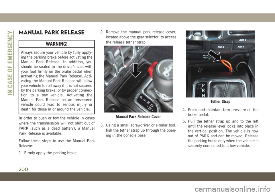
MANUAL PARK RELEASE
WARNING!
Always secure your vehicle by fully apply-
ing the parking brake before activating the
Manual Park Release. In addition, you
should be seated in the driver’s seat with
your foot firmly on the brake pedal when
activating the Manual Park Release. Acti-
vating the Manual Park Release will allow
your vehicle to roll away if it is not secured
by the parking brake, or by proper connec-
tion to a tow vehicle. Activating the
Manual Park Release on an unsecured
vehicle could lead to serious injury or
death for those in or around the vehicle.
In order to push or tow the vehicle in cases
where the transmission will not shift out of
PARK (such as a dead battery), a Manual
Park Release is available.
Follow these steps to use the Manual Park
Release:
1. Firmly apply the parking brake.2. Remove the manual park release cover,
located above the gear selector, to access
the release tether strap.
3. Using a small screwdriver or similar tool,
fish the tether strap up through the open-
ing in the console base.4. Press and maintain firm pressure on the
brake pedal.
5. Pull the tether strap up and to the left
until the release lever locks into place in
the vertical position. The vehicle is now
out of PARK and can be moved. Release
the parking brake only when the vehicle is
securely connected to a tow vehicle.
Manual Park Release Cover
Tether Strap
IN CASE OF EMERGENCY
200
Page 205 of 348
If the vehicle's battery is discharged, refer to
"Manual Park Release" in this section for
instructions on shifting the automatic trans-
mission out of PARK in order to move the
vehicle.
CAUTION!
• Do not use sling type equipment when
towing. Vehicle damage may occur.
• When securing the vehicle to a flatbed
truck, do not attach to front or rear
suspension components. Damage to
your vehicle may result from improper
towing.
• If the vehicle being towed requires steer-
ing, the ignition switch must be in the
ACC or ON/RUN mode, not in the OFF
mode.
Without The Key Fob
Special care must be taken when the vehicle
is towed with the ignition in the OFF mode.
The only approved method of towing without
the key fob is with a flatbed truck. Proper
towing equipment is necessary to prevent
damage to the vehicle.
Four–Wheel Drive Models
The manufacturer recommends towing with
all wheelsOFFthe ground. Acceptable meth-
ods are to tow the vehicle on a flatbed or with
one end of the vehicle raised and the opposite
end on a towing dolly.
If flatbed equipment is not available and the
transfer case is operable, the vehicle may be
towed (in the forward direction, withALL
wheels on the ground),IFthe transfer case is
inNEUTRAL(N) and the transmission is in
PARK. Refer to “Recreational Towing” in
“Starting And Operating” for detailed
instructions.
CAUTION!
• Front or rear wheel lifts must not be used
(if the remaining wheels are on the
ground). Internal damage to the trans-
mission or transfer case will occur if a
front or rear wheel lift is used when
towing.
• Towing this vehicle in violation of the
above requirements can cause severe
transmission and/or transfer case dam-
CAUTION!
age. Damage from improper towing is
not covered under the New Vehicle Lim-
ited Warranty.
Tow Eye Usage
Your vehicle is equipped with a tow eye that
can be used to move a disabled vehicle.
When using a tow eye be sure to follow the
“Tow Eye Usage Precautions” and the “Tow-
ing A Disabled Vehicle” instructions in this
section.
The tow eyes are mounted below the front and
rear bumpers.
Tow Eye Usage Precautions
WARNING!
Stand clear of vehicles when pulling with
tow eyes.
• Do not use a chain with a tow eye.
Chains may break, causing serious injury
or death.
203