tow bar JEEP WRANGLER UNLIMITED 2019 Owner handbook (in English)
[x] Cancel search | Manufacturer: JEEP, Model Year: 2019, Model line: WRANGLER UNLIMITED, Model: JEEP WRANGLER UNLIMITED 2019Pages: 348, PDF Size: 6.5 MB
Page 44 of 348
Icon Description
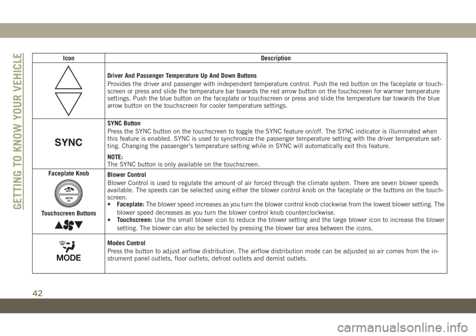
Driver And Passenger Temperature Up And Down Buttons
Provides the driver and passenger with independent temperature control. Push the red button on the faceplate or touch-
screen or press and slide the temperature bar towards the red arrow button on the touchscreen for warmer temperature
settings. Push the blue button on the faceplate or touchscreen or press and slide the temperature bar towards the blue
arrow button on the touchscreen for cooler temperature settings.
SYNC Button
Press the SYNC button on the touchscreen to toggle the SYNC feature on/off. The SYNC indicator is illuminated when
this feature is enabled. SYNC is used to synchronize the passenger temperature setting with the driver temperature set-
ting. Changing the passenger’s temperature setting while in SYNC will automatically exit this feature.
NOTE:
The SYNC button is only available on the touchscreen.
Faceplate Knob
Touchscreen Buttons
Blower Control
Blower Control is used to regulate the amount of air forced through the climate system. There are seven blower speeds
available. The speeds can be selected using either the blower control knob on the faceplate or the buttons on the touch-
screen.
•Faceplate:The blower speed increases as you turn the blower control knob clockwise from the lowest blower setting. The
blower speed decreases as you turn the blower control knob counterclockwise.
•Touchscreen:Use the small blower icon to reduce the blower setting and the large blower icon to increase the blower
setting. The blower can also be selected by pressing the blower bar area between the icons.
Modes Control
Press the button to adjust airflow distribution. The airflow distribution mode can be adjusted so air comes from the in-
strument panel outlets, floor outlets, defrost outlets and demist outlets.
GETTING TO KNOW YOUR VEHICLE
42
Page 143 of 348
STARTING AND OPERATING
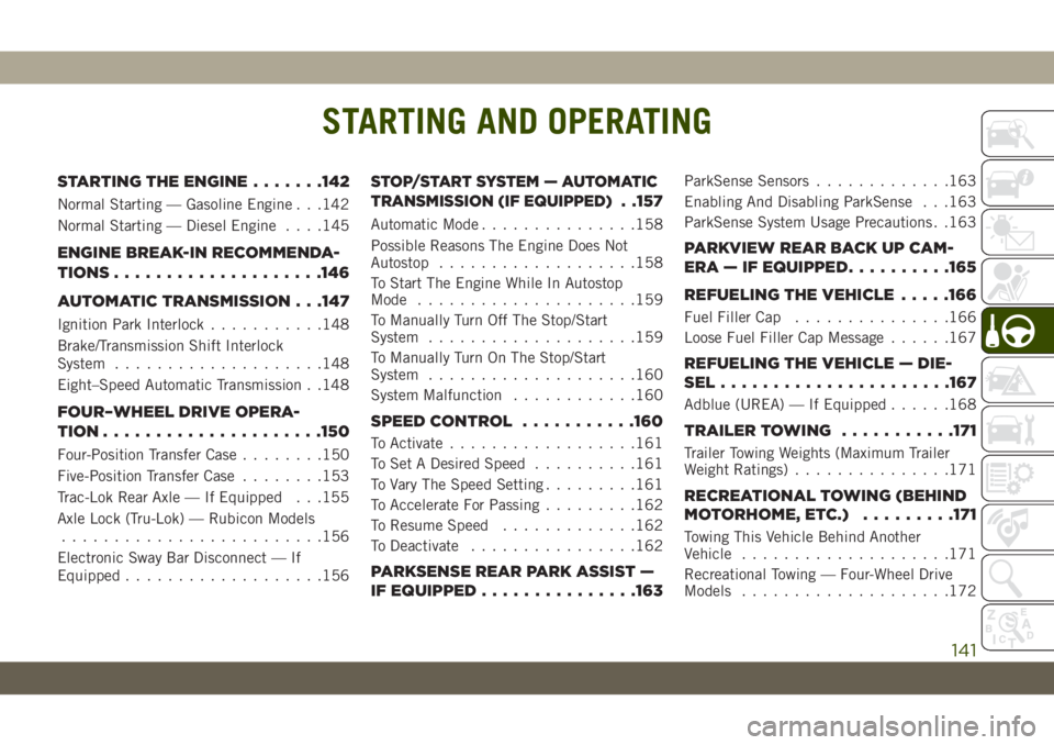
STARTING THE ENGINE.......142
Normal Starting — Gasoline Engine . . .142
Normal Starting — Diesel Engine. . . .145
ENGINE BREAK-IN RECOMMENDA-
TIONS....................146
AUTOMATIC TRANSMISSION . . .147
Ignition Park Interlock...........148
Brake/Transmission Shift Interlock
System....................148
Eight–Speed Automatic Transmission . .148
FOUR–WHEEL DRIVE OPERA-
TION.....................150
Four-Position Transfer Case........150
Five-Position Transfer Case........153
Trac-Lok Rear Axle — If Equipped . . .155
Axle Lock (Tru-Lok) — Rubicon Models
.........................156
Electronic Sway Bar Disconnect — If
Equipped...................156
STOP/START SYSTEM — AUTOMATIC
TRANSMISSION (IF EQUIPPED)
. .157
Automatic Mode...............158
Possible Reasons The Engine Does Not
Autostop...................158
To Start The Engine While In Autostop
Mode.....................159
To Manually Turn Off The Stop/Start
System....................159
To Manually Turn On The Stop/Start
System....................160
System Malfunction............160
SPEED CONTROL...........160
To Activate..................161
To Set A Desired Speed..........161
To Vary The Speed Setting.........161
To Accelerate For Passing.........162
To Resume Speed.............162
To Deactivate................162
PARKSENSE REAR PARK ASSIST —
IF EQUIPPED...............163
ParkSense Sensors.............163
Enabling And Disabling ParkSense . . .163
ParkSense System Usage Precautions . .163
PARKVIEW REAR BACK UP CAM-
ERA — IF EQUIPPED..........165
REFUELING THE VEHICLE.....166
Fuel Filler Cap...............166
Loose Fuel Filler Cap Message......167
REFUELING THE VEHICLE — DIE-
SEL......................167
Adblue (UREA) — If Equipped......168
TRAILER TOWING...........171
Trailer Towing Weights (Maximum Trailer
Weight Ratings)...............171
RECREATIONAL TOWING (BEHIND
MOTORHOME, ETC.).........171
Towing This Vehicle Behind Another
Vehicle....................171
Recreational Towing — Four-Wheel Drive
Models....................172
STARTING AND OPERATING
141
Page 174 of 348
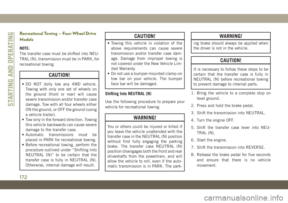
Recreational Towing — Four-Wheel Drive
Models
NOTE:
The transfer case must be shifted into NEU-
TRAL (N), transmission must be in PARK, for
recreational towing.
CAUTION!
• DO NOT dolly tow any 4WD vehicle.
Towing with only one set of wheels on
the ground (front or rear) will cause
severe transmission and/or transfer case
damage. Tow with all four wheels either
ON the ground, or OFF the ground (using
a vehicle trailer).
• Tow only in the forward direction. Towing
this vehicle backwards can cause severe
damage to the transfer case.
• Automatic transmissions must be
placed in PARK for recreational towing.
• Before recreational towing, perform the
procedure outlined under “Shifting Into
NEUTRAL (N)” to be certain that the
transfer case is fully in NEUTRAL (N).
Otherwise, internal damage will result.
CAUTION!
• Towing this vehicle in violation of the
above requirements can cause severe
transmission and/or transfer case dam-
age. Damage from improper towing is
not covered under the New Vehicle Lim-
ited Warranty.
• Do not use a bumper-mounted clamp-on
tow bar on your vehicle. The bumper
face bar will be damaged.
Shifting Into NEUTRAL (N)
Use the following procedure to prepare your
vehicle for recreational towing.
WARNING!
You or others could be injured or killed if
you leave the vehicle unattended with the
transfer case in the NEUTRAL (N) position
without first fully engaging the parking
brake. The transfer case NEUTRAL (N)
position disengages both the front and rear
driveshafts from the powertrain, and will
allow the vehicle to roll, even if the auto-
matic transmission is in PARK. The park-
WARNING!
ing brake should always be applied when
the driver is not in the vehicle.
CAUTION!
It is necessary to follow these steps to be
certain that the transfer case is fully in
NEUTRAL (N) before recreational towing
to prevent damage to internal parts.
1. Bring the vehicle to a complete stop on
level ground.
2. Press and hold the brake pedal.
3. Shift the transmission into NEUTRAL.
4. Turn the engine OFF.
5. Shift the transfer case lever into NEU-
TRAL (N).
6. Start the engine.
7. Shift the transmission into REVERSE.
8. Release the brake pedal for five seconds
and ensure that there is no vehicle
movement.
STARTING AND OPERATING
172
Page 175 of 348
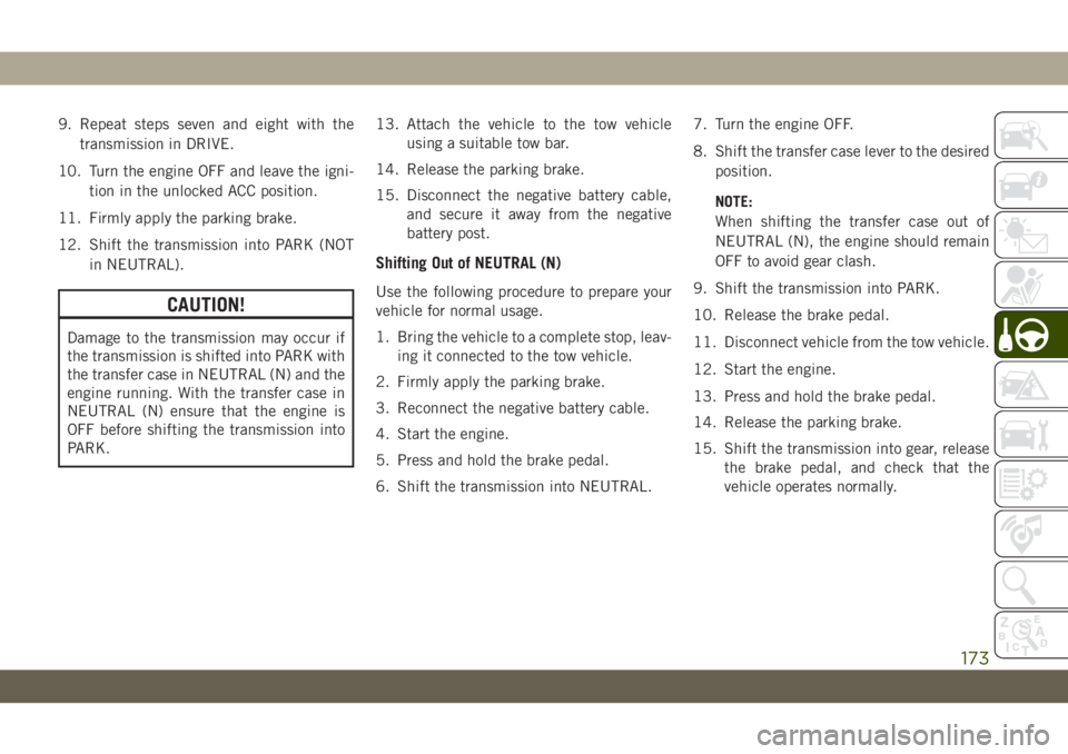
9. Repeat steps seven and eight with the
transmission in DRIVE.
10. Turn the engine OFF and leave the igni-
tion in the unlocked ACC position.
11. Firmly apply the parking brake.
12. Shift the transmission into PARK (NOT
in NEUTRAL).
CAUTION!
Damage to the transmission may occur if
the transmission is shifted into PARK with
the transfer case in NEUTRAL (N) and the
engine running. With the transfer case in
NEUTRAL (N) ensure that the engine is
OFF before shifting the transmission into
PARK.13. Attach the vehicle to the tow vehicle
using a suitable tow bar.
14. Release the parking brake.
15. Disconnect the negative battery cable,
and secure it away from the negative
battery post.
Shifting Out of NEUTRAL (N)
Use the following procedure to prepare your
vehicle for normal usage.
1. Bring the vehicle to a complete stop, leav-
ing it connected to the tow vehicle.
2. Firmly apply the parking brake.
3. Reconnect the negative battery cable.
4. Start the engine.
5. Press and hold the brake pedal.
6. Shift the transmission into NEUTRAL.7. Turn the engine OFF.
8. Shift the transfer case lever to the desired
position.
NOTE:
When shifting the transfer case out of
NEUTRAL (N), the engine should remain
OFF to avoid gear clash.
9. Shift the transmission into PARK.
10. Release the brake pedal.
11. Disconnect vehicle from the tow vehicle.
12. Start the engine.
13. Press and hold the brake pedal.
14. Release the parking brake.
15. Shift the transmission into gear, release
the brake pedal, and check that the
vehicle operates normally.
173
Page 186 of 348
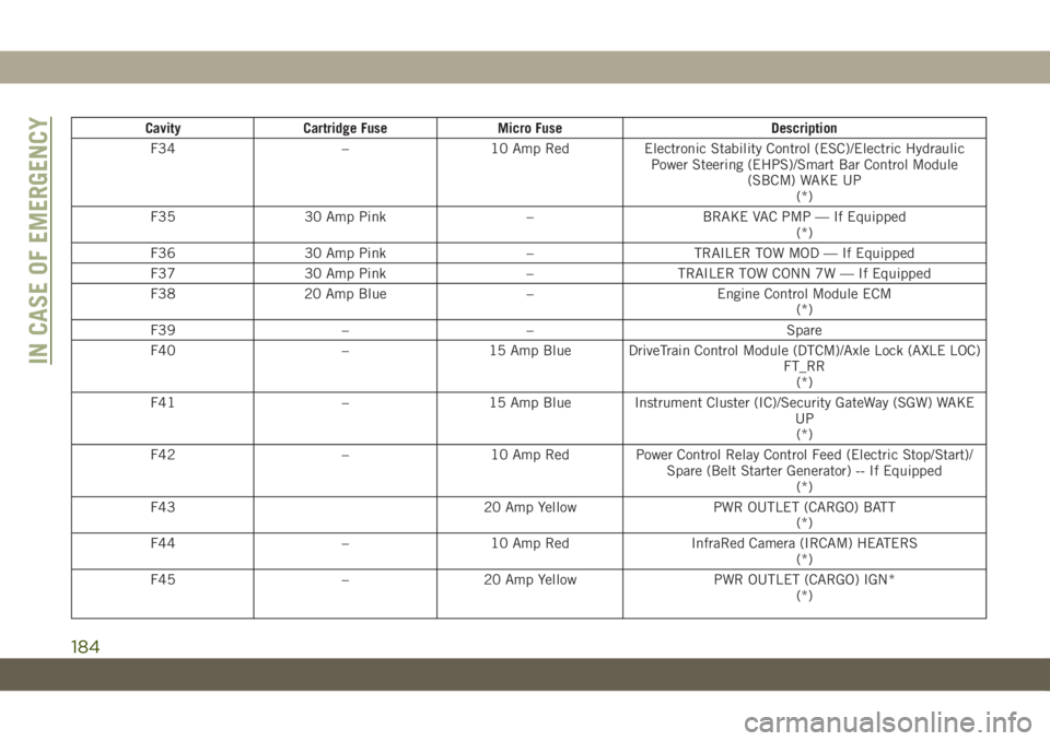
Cavity Cartridge Fuse Micro Fuse Description
F34 – 10 Amp Red Electronic Stability Control (ESC)/Electric Hydraulic
Power Steering (EHPS)/Smart Bar Control Module
(SBCM) WAKE UP
(*)
F35 30 Amp Pink – BRAKE VAC PMP — If Equipped
(*)
F36 30 Amp Pink – TRAILER TOW MOD — If Equipped
F37 30 Amp Pink – TRAILER TOW CONN 7W — If Equipped
F38 20 Amp Blue – Engine Control Module ECM
(*)
F39 – – Spare
F40 – 15 Amp Blue DriveTrain Control Module (DTCM)/Axle Lock (AXLE LOC)
FT_RR
(*)
F41 – 15 Amp Blue Instrument Cluster (IC)/Security GateWay (SGW) WAKE
UP
(*)
F42 – 10 Amp Red Power Control Relay Control Feed (Electric Stop/Start)/
Spare (Belt Starter Generator) -- If Equipped
(*)
F43 20 Amp Yellow PWR OUTLET (CARGO) BATT
(*)
F44 – 10 Amp Red InfraRed Camera (IRCAM) HEATERS
(*)
F45 – 20 Amp Yellow PWR OUTLET (CARGO) IGN*
(*)
IN CASE OF EMERGENCY
184
Page 196 of 348
Road Tire Installation
1. Mount the road tire on the axle.
2. Install the remaining lug nuts with the
cone shaped end of the nut toward the
wheel. Lightly tighten the lug nuts.
WARNING!
To avoid the risk of forcing the vehicle off
the jack, do not tighten the wheel nuts
fully until the vehicle has been lowered.
Failure to follow this warning may result in
serious injury.
3. Lower the vehicle to the ground by turning
the jack handle counterclockwise.
4. Finish tightening the lug nuts. Push down
on the wrench while at the end of the
handle for increased leverage. Tighten the
lug nuts in a star pattern until each nut
has been tightened twice. For the correct
lug nut torque refer to “Torque Specifica-
tions” in “Technical Specifications”. If in
doubt about the correct tightness, have
them checked with a torque wrench by an
authorized dealer or service station.5. After 25 miles (40 km), check the lug nut
torque with a torque wrench to ensure that
all lug nuts are properly seated against the
wheel.
Declaration Of Conformance
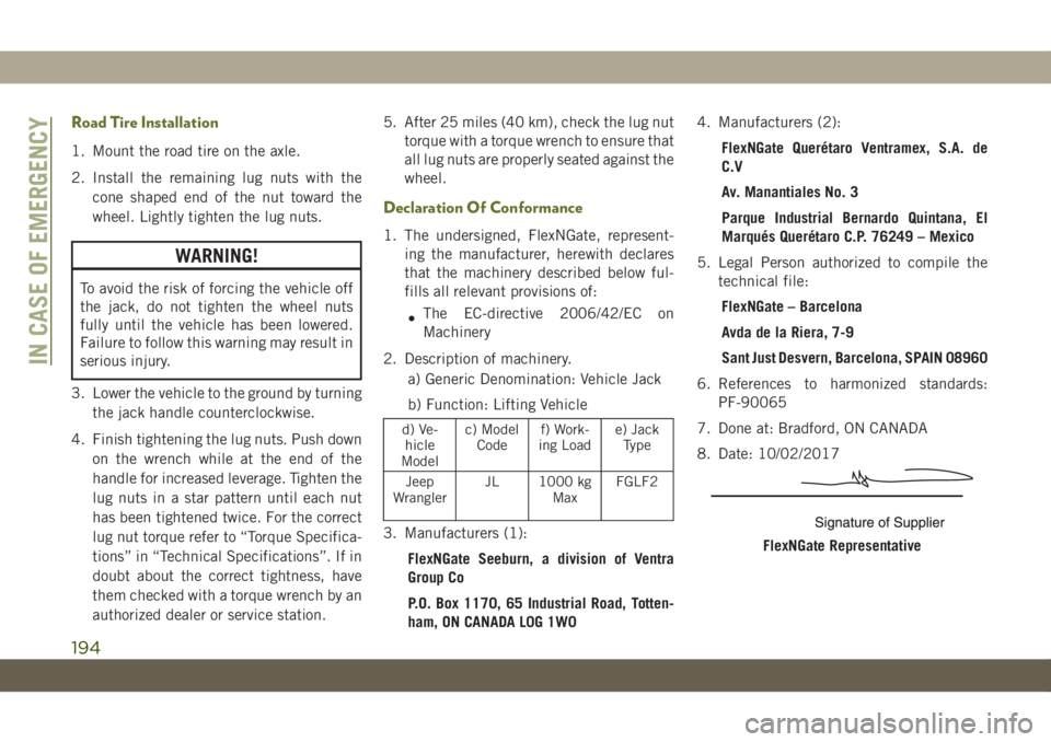
1. The undersigned, FlexNGate, represent-
ing the manufacturer, herewith declares
that the machinery described below ful-
fills all relevant provisions of:
•The EC-directive 2006/42/EC on
Machinery
2. Description of machinery.
a) Generic Denomination: Vehicle Jack
b) Function: Lifting Vehicle
d) Ve-
hicle
Modelc) Model
Codef) Work-
ing Loade) Jack
Type
Jeep
WranglerJL 1000 kg
MaxFGLF2
3. Manufacturers (1):
FlexNGate Seeburn, a division of Ventra
Group Co
P.O. Box 1170, 65 Industrial Road, Totten-
ham, ON CANADA L0G 1W04. Manufacturers (2):
FlexNGate Querétaro Ventramex, S.A. de
C.V
Av. Manantiales No. 3
Parque Industrial Bernardo Quintana, El
Marqués Querétaro C.P. 76249 – Mexico
5. Legal Person authorized to compile the
technical file:
FlexNGate – Barcelona
Avda de la Riera, 7-9
Sant Just Desvern, Barcelona, SPAIN 08960
6. References to harmonized standards:
PF-90065
7. Done at: Bradford, ON CANADA
8. Date: 10/02/2017FlexNGate Representative
IN CASE OF EMERGENCY
194
Page 204 of 348
TOWING A DISABLED
VEHICLE
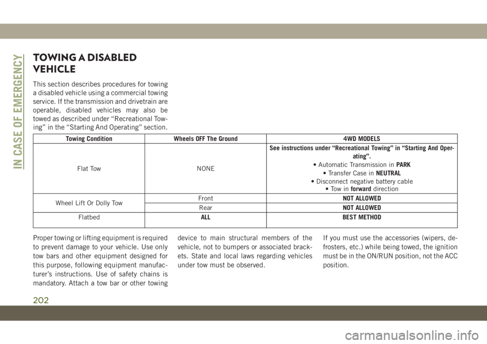
This section describes procedures for towing
a disabled vehicle using a commercial towing
service. If the transmission and drivetrain are
operable, disabled vehicles may also be
towed as described under “Recreational Tow-
ing” in the “Starting And Operating” section.
Towing Condition Wheels OFF The Ground 4WD MODELS
Flat Tow NONESee instructions under “Recreational Towing” in “Starting And Oper-
ating”.
• Automatic Transmission inPARK
• Transfer Case inNEUTRAL
• Disconnect negative battery cable
• Tow inforwarddirection
Wheel Lift Or Dolly TowFrontNOT ALLOWED
RearNOT ALLOWED
FlatbedALL BEST METHOD
Proper towing or lifting equipment is required
to prevent damage to your vehicle. Use only
tow bars and other equipment designed for
this purpose, following equipment manufac-
turer’s instructions. Use of safety chains is
mandatory. Attach a tow bar or other towingdevice to main structural members of the
vehicle, not to bumpers or associated brack-
ets. State and local laws regarding vehicles
under tow must be observed.If you must use the accessories (wipers, de-
frosters, etc.) while being towed, the ignition
must be in the ON/RUN position, not the ACC
position.
IN CASE OF EMERGENCY
202
Page 206 of 348
WARNING!
• Do not use a tow strap with a tow eye.
Tow straps may break or become disen-
gaged, causing serious injury or death.
• Failure to follow proper tow eye usage
may cause components to break result-
ing in serious injury or death.
• The brake and steering power assist sys-
tems will not function while the vehicle
is being towed. You will, therefore, need
to apply more force on the brake pedal
and steering wheel. Do not use flexible
ropes when towing, and avoid jerky
movements. Do not start the engine
while towing the car. Before tightening
the ring, clean the threaded housing
thoroughly. Make sure that the ring is
fully screwed into the housing before
towing the car.
CAUTION!
• The tow eye must only be used for road-
side emergencies. Use with an appropri-
ate device in accordance with highway
code (a rigid bar) to maneuver the ve-
hicle in preparation for transport via a
tow truck.
• The tow eye must not be used to move
the vehicle off the road or where there
are obstacles.
• Do not use the tow eyes for tow truck
hookup or highway towing.
• Do not use the tow eye to free a stuck
vehicle. Refer to the “Freeing A Stuck
Vehicle” section for further information.
• Please refer to the “Towing A Disabled
Vehicle” section for detailed instruc-
tions. Damage to your vehicle may occur
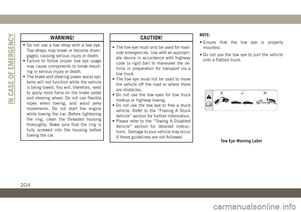
if these guidelines are not followed.NOTE:
• Ensure that the tow eye is properly
mounted.
• Do not use the tow eye to pull the vehicle
onto a flatbed truck.
Tow Eye Warning Label
IN CASE OF EMERGENCY
204
Page 343 of 348
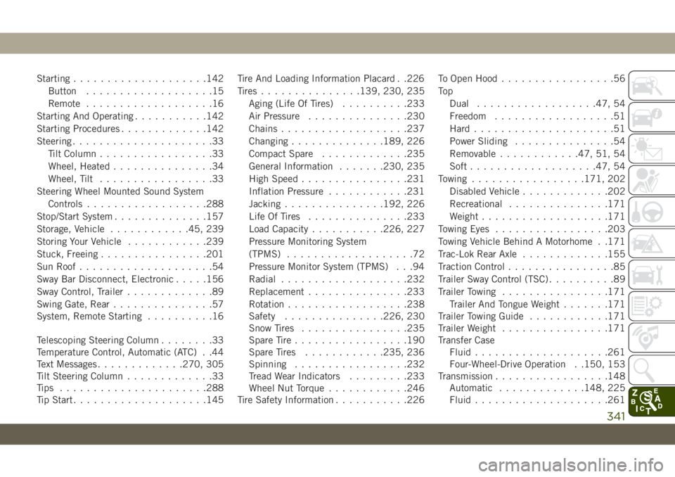
Starting....................142
Button...................15
Remote...................16
Starting And Operating...........142
Starting Procedures.............142
Steering.....................33
Tilt Column.................33
Wheel, Heated...............34
Wheel, Tilt.................33
Steering Wheel Mounted Sound System
Controls..................288
Stop/Start System..............157
Storage, Vehicle............45, 239
Storing Your Vehicle............239
Stuck, Freeing................201
Sun Roof....................54
Sway Bar Disconnect, Electronic.....156
Sway Control, Trailer.............89
Swing Gate, Rear...............57
System, Remote Starting..........16
Telescoping Steering Column........33
Temperature Control, Automatic (ATC) . .44
Text Messages.............270, 305
Tilt Steering Column.............33
Tips ......................288
Tip Start....................145Tire And Loading Information Placard . .226
Tires...............139, 230, 235
Aging (Life Of Tires)..........233
Air Pressure...............230
Chains...................237
Changing..............189, 226
Compact Spare.............235
General Information.......230, 235
High Speed................231
Inflation Pressure............231
Jacking...............192, 226
Life Of Tires...............233
Load Capacity...........226, 227
Pressure Monitoring System
(TPMS)...................72
Pressure Monitor System (TPMS) . . .94
Radial..................
.232
Replacement...............233
Rotation..................238
Safety...............226, 230
Snow Tires................235
Spare Tire.................190
Spare Tires............235, 236
Spinning.................232
Tread Wear Indicators.........233
Wheel Nut Torque............246
Tire Safety Information...........226To Open Hood.................56
To p
Dual..................47, 54
Freedom..................51
Hard.....................51
Power Sliding...............54
Removable............47, 51, 54
Soft...................47, 54
Towing.................171, 202
Disabled Vehicle.............202
Recreational...............171
Weight...................171
Towing Eyes.................203
Towing Vehicle Behind A Motorhome . .171
Trac-Lok Rear Axle.............155
Traction Control................85
Trailer Sway Control (TSC)..........89
Trailer Towing................171
Trailer And Tongue Weight.......171
Trailer Towing Guide............171
Trailer Weight................171
Transfer Case
Fluid....................261
Four-Wheel-Drive Operation . .150, 153
Transmission.................148
Automatic.............148, 225
Fluid....................261
341