fuse diagram JEEP XJ 1995 Service And Repair Manual
[x] Cancel search | Manufacturer: JEEP, Model Year: 1995, Model line: XJ, Model: JEEP XJ 1995Pages: 2158, PDF Size: 81.9 MB
Page 1202 of 2158
REAR LIGHTING
TAIL LAMPS AND LICENSE PLATE LAMPS
Circuit A6 in the Power Distribution Center (PDC)
connects to a bus bar in the fuse block. The fuse
block bus bar powers circuit F33. Circuit F33 con-
nects to the headlamp switch. Fuse 3 in the PDC
protects circuit A3. Fuse 8 in the fuse block protects
circuit F33.
The headlamp switch has three positions: ON,
PARK (parking lamps) and OFF, plus a dimmer
switch. When the headlamp switch is in the PARK or
ON position, the switch connects circuit F33 to cir-
cuit L7. From the headlamp switch, circuit L7
branches to power the front parking lamps and rear
tail and license plate lamps. The lamps are case
grounded.
HELPFUL INFORMATION
²If the vehicle is equipped with factory installed fog
lamps, circuit L7 splices to feed the park lamp relay.
²Jumper harnesses connect the tail, stop, turn sig-
nal lamp to the body harness.
²Check fuse 3 in the PDC.
²Check fuse 8 in the fuse block.
²Circuit L7 also feeds the radio, if equipped.
STOP LAMPS AND CHMSL LAMPS
Circuit A6 from fuse 3 in the Power Distribution
Center (PDC) supplies voltage to the fuse block bus
bar. The bus bar powers circuit F32 through fuse 3 in
the fuse block. Circuit F32 connects to the stop lamp
switch.
When the operator depresses the brake pedal, the
stop lamp switch closes, and connects circuit F32 to
circuit L50. Circuit L50 connects to the CHMSL
lamps and turn signal/hazard flasher. Circuit Z1 pro-
vides ground for the CHMSL lamps. The turn signal/
hazard flasher supplies current to the L62 and L63
circuits. Circuit L62 powers the right stop lamp. Cir-
cuit L63 powers the left stop lamp. The stop lamps
are case grounded.
HELPFUL INFORMATION
²Circuits L50 and Z1 pass through contacts in the
rear door before reaching the CHMSL lamps.
²Check fuse 3 in the PDC.²Check fuse 3 in the fuse block.
²Check for continuity across the stop lamp switch
when it is closed.
²If the vehicle is equipped with anti-lock brakes,
circuit L50 connects to the ABS module.
BACK-UP LAMPS
In the START or RUN position, the ignition switch
connects circuit A1 from fuse 4 in the Power Distri-
bution Center (PDC) to circuit A21. Circuit A21 feeds
a bus bar in the fuse block that powers circuit G5
through fuse 9.
Circuit G5 splices to supply power to the back-up
lamp switch. On automatic transmission vehicles, the
back-up lamp switch is part of an assembly that in-
cludes the PARK/NEUTRAL position switch.
When the operator puts the transmission in Re-
verse, the back-up lamp switch connects circuit G5 to
circuit L1. Circuit L1 feeds the case grounded
back-up lamps.
HELPFUL INFORMATION
²Check fuse 4 in the PDC.
²Check fuse 9 in the fuse block.
²Check for continuity across the back-up lamp
switch when it is closed.
DIAGRAM INDEX
Component Page
ABS Control Module......................8W-51-3
Back-Up Lamps..........................8W-51-4
Back-Up Lamp Switch.....................8W-51-2
Center High Mounted Stop Lamps (CHMSL).......8W-51-3
Fuse 3 (Fuse Block).......................8W-51-2
Fuse 3 (PDC)...........................8W-51-2
Fuse 4 (PDC)...........................8W-51-2
Fuse 9 (Fuse Block).......................8W-51-2
Fuse 8 (Fuse Block).......................8W-51-2
Headlamp Switch.........................8W-51-2
Ignition Switch..........................8W-51-2
Powertrain Control Module..................8W-51-3
Stop Lamp Switch........................8W-51-3
Tail, Stop, and Turn Signal Lamps.............8W-51-4
J8W-51 REAR LIGHTINGÐYJ VEHICLES 8W - 51 - 1
Page 1206 of 2158
TURN SIGNALS
TURN SIGNALS
In the ACCESSORY or RUN position, the ignition
switch connects circuit A1 from fuse 4 in the Power
Distribution Center (PDC) to circuit A31. Circuit A31
feeds circuit L5 through fuse 4 in the fuse block.
Circuit L5 powers the turn signal flasher. Circuit
L6 from the flasher connects to the turn signal/haz-
ard flasher switch which supplies current to the turn
signals. The switch connects to the turn signal and
side marker lamps on circuits L60, L61, L62 and
L63.
RIGHT TURN SIGNAL
When the operator selects the right turn signal, the
turn signal/hazard flasher switch connects power
from circuit L6 to circuits L60 and L62. Circuit L62
feeds the right rear turn signal/hazard flasher/stop
lamp.
Circuit L60 feeds the right front turn signal/hazard
flasher lamp and side marker lamp. Circuit L60 also
splices to power the turn signal indicator lamp on the
instrument cluster.
LEFT TURN SIGNAL
When the operator selects the left turn signal, the
turn signal/hazard flasher switch connects power
from circuit L6 to circuits L61 and L63. Circuit L63
feeds the left rear turn signal/hazard flasher/stop
lamp.
Circuit L61 feeds the left front turn signal/hazard
flasher lamp and side marker lamp. Circuit L61 also
splices to power the turn signal indicator lamp on the
instrument cluster.
GROUND CIRCUIT
Circuit Z1 provides a ground for the left front park
and turn signal lamp, side marker lamp and head
lamp. The grounding point for circuit Z1 is the radi-
ator left support.
Circuit Z1 provides a ground for the right front
park and turn signal lamp, side marker lamp and
head lamp. The grounding point for circuit Z1 is the
radiator right support.
HELPFUL INFORMATION
²Check fuse 4 in the PDC.
²Check fuse 4 in the fuse block.
HAZARD FLASHERS
Circuit L9 from fuse 5 in the Power Distribution
Center (PDC) supplies power to the hazard flasher.
Circuit L19 from the flasher connects to the turn sig-
nal/hazard flasher switch.When the operator presses the hazard flasher but-
ton, the turn signal/hazard flasher switch connects
circuit L19 to circuits L60, L61, L62, and L63. Cir-
cuit L62 powers the right rear turn signal/stop/haz-
ard lamp. Circuit L63 powers the left rear turn
signal/stop/hazard lamp. Circuit L60 powers the right
front indicator lamp. Circuit L61 powers the left
front lamp.
Circuit L60 also splices to feed the instrument clus-
ter right indicator lamp. Circuit L61 splices to feed
the instrument cluster left indicator lamp.
GROUND CIRCUIT
The rear turn signal/stop/hazard lamps are case
grounded.
Circuit Z1 provides a ground for the left front park
and turn signal lamp, side marker lamp and head
lamp. The grounding point for circuit Z1 is the radi-
ator left support.
Circuit Z1 provides a ground for the right left park
and turn signal lamp, side marker lamp and head
lamp. The grounding point for circuit Z1 is the radi-
ator right support.
HELPFUL INFORMATION
Check fuse 5 in the PDC.
DIAGRAM INDEX
Component Page
ABS Control Module......................8W-52-2
Fuse 3 (Fuse Block).......................8W-52-2
Fuse 3 (PDC)...........................8W-52-2
Fuse 4 (Fuse Block).......................8W-52-2
Fuse 4 (PDC)...........................8W-52-2
Fuse 5 (PDC)...........................8W-52-2
Hazard Flasher..........................8W-52-2
Ignition Switch..........................8W-52-2
Instrument Cluster Turn Signal Lamps...........8W-52-3
Stop Lamp Switch........................8W-52-2
Turn Signal Flasher.......................8W-52-2
Turn Signal/Hazard Flasher Switch..............8W-52-3
J8W-52 TURN SIGNALSÐYJ VEHICLES 8W - 52 - 1
Page 1210 of 2158
WIPERS
INDEX
page page
Diagram Index............................ 2
Rear Wiper System......................... 1WipersÐIntermittent........................ 1
WipersÐStandard.......................... 1
WIPERSÐSTANDARD
A circuit breaker in the fuse block powers the stan-
dard wiper system. The standard wiper system oper-
ates at either LOW or HIGH speeds.
In the ACCESSORY or RUN position, the ignition
switch connects circuit A1 from fuse 4 in the Power
Distribution Center (PDC) with circuit A31. Circuit
A31 supplies voltage to circuit V6 through the circuit
breaker in cavity 11 of the fuse block.
Circuit V6 is double crimped at the circuit breaker
and supplies power to the wiper switch and the park
switch in the wiper motor. Circuit Z1 provides
ground for the wiper motor and switch.
When the operator moves the wiper switch to the
LOW position, battery voltage passes through the
switch to circuit V3. Circuit V3 feeds the wiper motor
low speed brushes. If the operator selects wiper
HIGH speed operation, the wiper switch passes cur-
rent to circuit V4. Circuit V4 feeds the wiper motor
high speed brushes.
As the windshield wiper motor turns, the park
switch, internal to the motor, moves from its DOWN
position to the UP position. When the wiper switch is
turned OFF, the V5 circuit prevents the wipers from
stopping in any position but park.
The windshield washer uses a pump motor located
inside the windshield washer fluid reservoir. When
the washer switch is pressed, power is supplied
through the wiper switch to the pump motor on cir-
cuit V10. Circuit Z1 provide ground for the pump mo-
tor.
WIPERSÐINTERMITTENT
A circuit breaker in the fuse block powers the in-
termittent wiper system. The wiper system operates
at either LOW, HIGH, or DELAY speeds.
In the ACCESSORY or RUN position, the ignition
switch connects circuit A1 from fuse 4 in the Power
Distribution Center (PDC) with circuit A31. Circuit
A31 supplies voltage to circuit V6 through the circuit
breaker in cavity 11 of the fuse block.
Circuit V6 is double crimped at the circuit breaker
and supplies power to the wiper switch and the park
switch in the wiper motor. Circuit Z1 provides
ground for the wiper motor and switch.When the operator moves the wiper switch to the
LOW position, battery voltage passes through the
switch to circuit V3. Circuit V3 feeds the wiper motor
low speed brushes. If the operator selects wiper
HIGH speed operation, the wiper switch passes cur-
rent to circuit V4. Circuit V4 feeds the wiper motor
high speed brushes.
The DELAY portion of the wiper switch contains a
variable resistor. The variable resistor connects to
the intermittent wiper module through the wiper
switch harness. The amount of delay selected by the
operator determines the voltage drop through the re-
sistor and the voltage level received by the intermit-
tent wiper module.
After the intermittent wiper control module deter-
mines the amount of delay selected, it cycles the wip-
ers by periodically energizing circuit V3. Circuit V3
powers the wiper motor low speed brushes.
As the windshield wiper motor turns, the park
switch, internal to the motor, moves from its DOWN
position to the UP position. When the wiper switch is
turned OFF, the V5 circuit prevents the wipers from
stopping in any position but park.
The windshield washer uses a pump motor located
inside the windshield washer fluid reservoir. When
the washer switch is pressed, power is supplied
through the wiper switch to the pump motor on cir-
cuit V10. Circuit Z1 provides ground for the pump
motor.
REAR WIPER SYSTEM
In the RUN position, the ignition switch connects
circuit A1 from fuse 4 in the Power Distribution Cen-
ter (PDC) with circuit A22. Circuit A22 connects to a
fuse block in the bus bar that powers circuit V23
through the fuse in cavity 1.
Circuit V23 supplies power to the park switch in
the rear wiper motor. Also, circuit V22 is crimped to
circuit V23 at the rear wiper motor connector. Circuit
V22 supplies current to the rear wiper switch.
In the WIPE or WASH positions, the rear wiper
switch supplies voltage to the wiper motor on circuit
V13. Circuit Z1 provides ground for the wiper motor.
J8W-53 WIPERSÐYJ VEHICLES 8W - 53 - 1
Page 1211 of 2158
The rear windshield washer uses a pump motor lo-
cated inside the windshield washer fluid reservoir.
When the rear wiper switch is pressed, power is sup-
plied through the wiper switch to the pump motor on
circuit V20. Circuit Z1 provides ground for the pump
motor.DIAGRAM INDEX
Component Page
Circuit Breaker (Fuse Block Cavity 11).........8W-53-4, 5
Fuse 4 (PDC).......................8W-53-3, 4, 5,
Fuse 4 (Fuse Block).....................8W-53-4, 5
Fuse 7 (Fuse Block).....................8W-53-4, 5
Ignition Switch......................8W-53-3, 4, 5
Intermittent Wiper Control Module.............8W-53-5
Intermittent Wiper Switch...................8W-53-5
Rear Windshield Washer Pump Motor...........8W-53-3
Rear Wiper Motor........................8W-53-3
Standard Wiper Switch.....................8W-53-4
Windshield Washer Pump Motor.............8W-53-4, 5
Wiper Motor..........................8W-53-4, 5
8W - 53 - 2 8W-53 WIPERSÐYJ VEHICLESJ
Page 1262 of 2158
CONNECTOR LOCATIONS
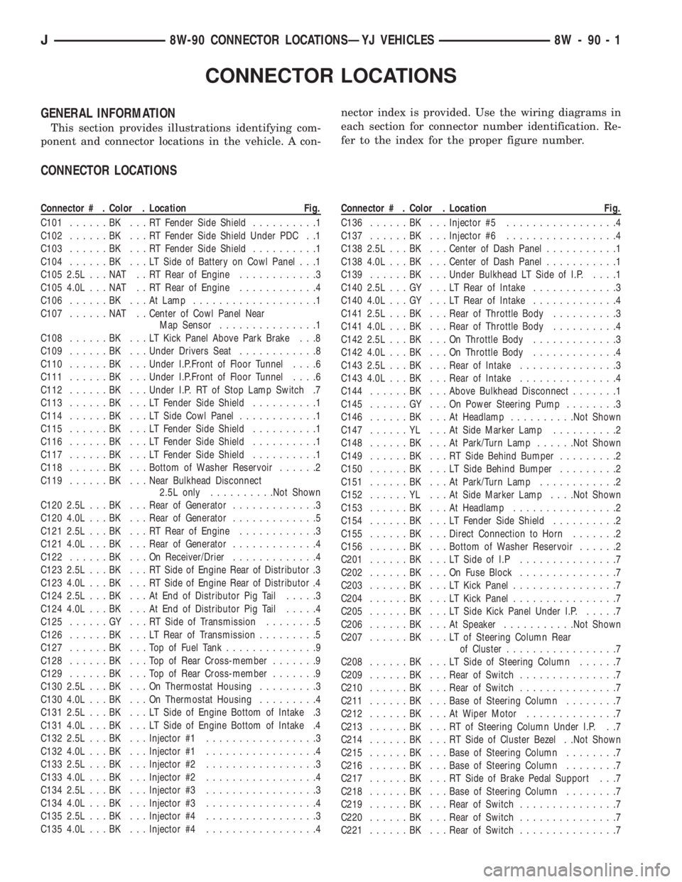
GENERAL INFORMATION
This section provides illustrations identifying com-
ponent and connector locations in the vehicle. A con-nector index is provided. Use the wiring diagrams in
each section for connector number identification. Re-
fer to the index for the proper figure number.
CONNECTOR LOCATIONS
Connector # . Color . Location Fig.
C101......BK ...RTFender Side Shield..........1
C102......BK ...RTFender Side Shield Under PDC . .1
C103......BK ...RTFender Side Shield..........1
C104......BK ...LTSide of Battery on Cowl Panel . . .1
C105 2.5L . . . NAT . . RT Rear of Engine............3
C105 4.0L . . . NAT . . RT Rear of Engine............4
C106......BK ...AtLamp...................1
C107......NAT ..Center of Cowl Panel Near
Map Sensor...............1
C108......BK ...LTKick Panel Above Park Brake . . .8
C109......BK ...Under Drivers Seat............8
C110......BK ...Under I.P.Front of Floor Tunnel....6
C111......BK ...Under I.P.Front of Floor Tunnel....6
C112......BK ...Under I.P. RT of Stop Lamp Switch .7
C113......BK ...LTFender Side Shield..........1
C114......BK ...LTSide Cowl Panel............1
C115......BK ...LTFender Side Shield..........1
C116......BK ...LTFender Side Shield..........1
C117......BK ...LTFender Side Shield..........1
C118......BK ...Bottom of Washer Reservoir......2
C119......BK ...Near Bulkhead Disconnect
2.5L only..........Not Shown
C120 2.5L . . . BK . . . Rear of Generator.............3
C120 4.0L . . . BK . . . Rear of Generator.............5
C121 2.5L . . . BK . . . RT Rear of Engine............3
C121 4.0L . . . BK . . . Rear of Generator.............4
C122......BK ...OnReceiver/Drier.............4
C123 2.5L . . . BK . . . RT Side of Engine Rear of Distributor .3
C123 4.0L . . . BK . . . RT Side of Engine Rear of Distributor .4
C124 2.5L . . . BK . . . At End of Distributor Pig Tail.....3
C124 4.0L . . . BK . . . At End of Distributor Pig Tail.....4
C125......GY ...RTSide of Transmission........5
C126......BK ...LTRear of Transmission.........5
C127......BK ...TopofFuel Tank..............9
C128......BK ...TopofRear Cross-member.......9
C129......BK ...TopofRear Cross-member.......9
C130 2.5L . . . BK . . . On Thermostat Housing.........3
C130 4.0L . . . BK . . . On Thermostat Housing.........4
C131 2.5L . . . BK . . . LT Side of Engine Bottom of Intake .3
C131 4.0L . . . BK . . . LT Side of Engine Bottom of Intake .4
C132 2.5L . . . BK . . . Injector #1.................3
C132 4.0L . . . BK . . . Injector #1.................4
C133 2.5L . . . BK . . . Injector #2.................3
C133 4.0L . . . BK . . . Injector #2.................4
C134 2.5L . . . BK . . . Injector #3.................3
C134 4.0L . . . BK . . . Injector #3.................4
C135 2.5L . . . BK . . . Injector #4.................3
C135 4.0L . . . BK . . . Injector #4.................4Connector # . Color . Location Fig.
C136......BK ...Injector #5.................4
C137......BK ...Injector #6.................4
C138 2.5L . . . BK . . . Center of Dash Panel...........1
C138 4.0L . . . BK . . . Center of Dash Panel...........1
C139......BK ...Under Bulkhead LT Side of I.P.....1
C140 2.5L . . . GY . . . LT Rear of Intake.............3
C140 4.0L . . . GY . . . LT Rear of Intake.............4
C141 2.5L . . . BK . . . Rear of Throttle Body..........3
C141 4.0L . . . BK . . . Rear of Throttle Body..........4
C142 2.5L . . . BK . . . On Throttle Body.............3
C142 4.0L . . . BK . . . On Throttle Body.............4
C143 2.5L . . . BK . . . Rear of Intake...............3
C143 4.0L . . . BK . . . Rear of Intake...............4
C144......BK ...Above Bulkhead Disconnect.......1
C145......GY ...OnPower Steering Pump........3
C146......BK ...AtHeadlamp..........Not Shown
C147......YL ...AtSide Marker Lamp..........2
C148......BK ...AtPark/Turn Lamp......Not Shown
C149......BK ...RTSide Behind Bumper.........2
C150......BK ...LTSide Behind Bumper.........2
C151......BK ...AtPark/Turn Lamp............2
C152......YL ...AtSide Marker Lamp. . . .Not Shown
C153......BK ...AtHeadlamp................2
C154......BK ...LTFender Side Shield..........2
C155......BK ...Direct Connection to Horn.......2
C156......BK ...Bottom of Washer Reservoir......2
C201......BK ...LTSide of I.P...............7
C202......BK ...OnFuse Block...............7
C203......BK ...LTKick Panel................7
C204......BK ...LTKick Panel................7
C205......BK ...LTSide Kick Panel Under I.P......7
C206......BK ...AtSpeaker...........Not Shown
C207......BK ...LTofSteering Column Rear
of Cluster.................7
C208......BK ...LTSide of Steering Column......7
C209......BK ...Rear of Switch...............7
C210......BK ...Rear of Switch...............7
C211......BK ...Base of Steering Column........7
C212......BK ...AtWiper Motor..............7
C213......BK ...RTofSteering Column Under I.P. . .7
C214......BK ...RTSide of Cluster Bezel . .Not Shown
C215......BK ...Base of Steering Column........7
C216......BK ...Base of Steering Column........7
C217......BK ...RTSide of Brake Pedal Support . . .7
C218......BK ...Base of Steering Column........7
C219......BK ...Rear of Switch...............7
C220......BK ...Rear of Switch...............7
C221......BK ...Rear of Switch...............7
J8W-90 CONNECTOR LOCATIONSÐYJ VEHICLES 8W - 90 - 1
Page 2096 of 2158
off switch for battery voltage. If no voltage is present
test pressure cut-off switch. If voltage is present go
to next step.
(5) With ohmmeter test harness connector ground
circuit for continuity to ground. If circuit is open, (no
continuity) repair ground circuit. If circuit test OK
and clutch does not engage refer to Powertrain Diag-
nostic Service Manual for A/C clutch circuit test.
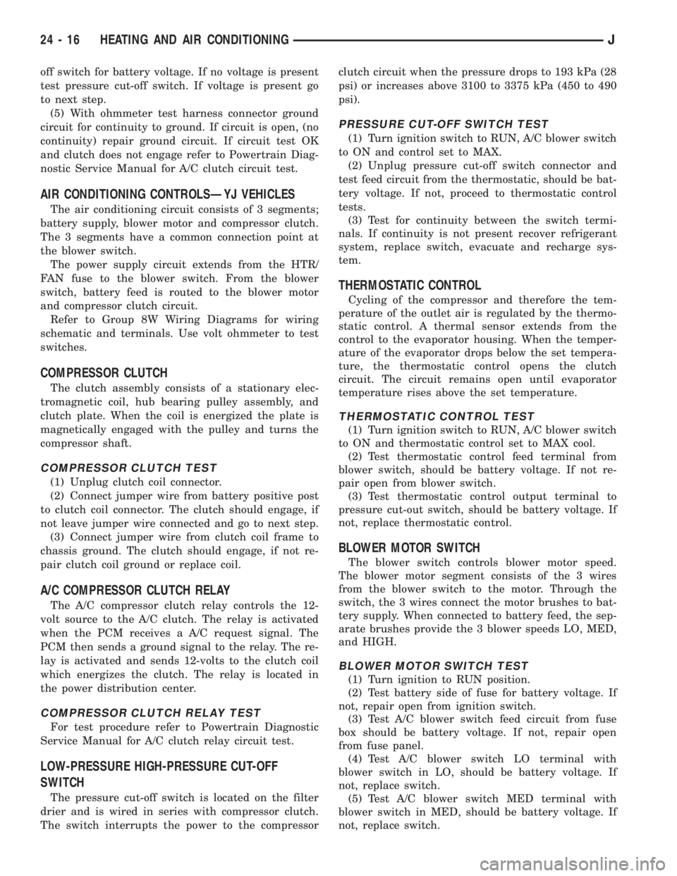
AIR CONDITIONING CONTROLSÐYJ VEHICLES
The air conditioning circuit consists of 3 segments;
battery supply, blower motor and compressor clutch.
The 3 segments have a common connection point at
the blower switch.
The power supply circuit extends from the HTR/
FAN fuse to the blower switch. From the blower
switch, battery feed is routed to the blower motor
and compressor clutch circuit.
Refer to Group 8W Wiring Diagrams for wiring
schematic and terminals. Use volt ohmmeter to test
switches.
COMPRESSOR CLUTCH
The clutch assembly consists of a stationary elec-
tromagnetic coil, hub bearing pulley assembly, and
clutch plate. When the coil is energized the plate is
magnetically engaged with the pulley and turns the
compressor shaft.
COMPRESSOR CLUTCH TEST
(1) Unplug clutch coil connector.
(2) Connect jumper wire from battery positive post
to clutch coil connector. The clutch should engage, if
not leave jumper wire connected and go to next step.
(3) Connect jumper wire from clutch coil frame to
chassis ground. The clutch should engage, if not re-
pair clutch coil ground or replace coil.
A/C COMPRESSOR CLUTCH RELAY
The A/C compressor clutch relay controls the 12-
volt source to the A/C clutch. The relay is activated
when the PCM receives a A/C request signal. The
PCM then sends a ground signal to the relay. The re-
lay is activated and sends 12-volts to the clutch coil
which energizes the clutch. The relay is located in
the power distribution center.
COMPRESSOR CLUTCH RELAY TEST
For test procedure refer to Powertrain Diagnostic
Service Manual for A/C clutch relay circuit test.
LOW-PRESSURE HIGH-PRESSURE CUT-OFF
SWITCH
The pressure cut-off switch is located on the filter
drier and is wired in series with compressor clutch.
The switch interrupts the power to the compressorclutch circuit when the pressure drops to 193 kPa (28
psi) or increases above 3100 to 3375 kPa (450 to 490
psi).
PRESSURE CUT-OFF SWITCH TEST
(1) Turn ignition switch to RUN, A/C blower switch
to ON and control set to MAX.
(2) Unplug pressure cut-off switch connector and
test feed circuit from the thermostatic, should be bat-
tery voltage. If not, proceed to thermostatic control
tests.
(3) Test for continuity between the switch termi-
nals. If continuity is not present recover refrigerant
system, replace switch, evacuate and recharge sys-
tem.
THERMOSTATIC CONTROL
Cycling of the compressor and therefore the tem-
perature of the outlet air is regulated by the thermo-
static control. A thermal sensor extends from the
control to the evaporator housing. When the temper-
ature of the evaporator drops below the set tempera-
ture, the thermostatic control opens the clutch
circuit. The circuit remains open until evaporator
temperature rises above the set temperature.
THERMOSTATIC CONTROL TEST
(1) Turn ignition switch to RUN, A/C blower switch
to ON and thermostatic control set to MAX cool.
(2) Test thermostatic control feed terminal from
blower switch, should be battery voltage. If not re-
pair open from blower switch.
(3) Test thermostatic control output terminal to
pressure cut-out switch, should be battery voltage. If
not, replace thermostatic control.
BLOWER MOTOR SWITCH
The blower switch controls blower motor speed.
The blower motor segment consists of the 3 wires
from the blower switch to the motor. Through the
switch, the 3 wires connect the motor brushes to bat-
tery supply. When connected to battery feed, the sep-
arate brushes provide the 3 blower speeds LO, MED,
and HIGH.
BLOWER MOTOR SWITCH TEST
(1) Turn ignition to RUN position.
(2) Test battery side of fuse for battery voltage. If
not, repair open from ignition switch.
(3) Test A/C blower switch feed circuit from fuse
box should be battery voltage. If not, repair open
from fuse panel.
(4) Test A/C blower switch LO terminal with
blower switch in LO, should be battery voltage. If
not, replace switch.
(5) Test A/C blower switch MED terminal with
blower switch in MED, should be battery voltage. If
not, replace switch.
24 - 16 HEATING AND AIR CONDITIONINGJ
Page 2097 of 2158
(6) Test A/C blower switch HIGH terminal with
blower switch in HIGH, should be battery voltage. If
not, replace switch.
BLOWER MOTOR
The A/C blower motor is attached to the evaporator
housing mounted under the instrument panel. The
motor has a ground wire and 3 wires connect to the
motor brushes. When voltage is applied to the sepa-
rate brushes it provides the 3 blower speeds LO,
MED, and HIGH.
BLOWER MOTOR TEST
Turn ignition switch to RUN for voltage tests and
turn ignition switch to OFF for resistance test.
(1) Test A/C blower motor ground terminal should
be 0 ohms. If not, repair ground circuit.
(2) Test A/C blower motor connector LO terminal
with blower switch in LO, should be battery voltage.
If not repair open from blower switch. If the blower
motor is still inoperative replace motor.
(3) Test A/C blower motor connector MED terminal
with blower switch in MED, should be battery volt-
age. If not repair open from blower switch. If the
blower motor is still inoperative replace motor.
(4) Test A/C blower motor connector HIGH termi-
nal with blower switch in HIGH, should be battery
voltage. If not, repair open from blower switch. If the
blower motor is still inoperative, replace motor.
HEATER DIAGNOSIS
On LHD XJ vehicles a water valve controls coolant
flow to the heater core. The valve is vacuum oper-
ated. When vacuum is applied, the valve opens and
coolant is directed through the heater core and back
to the engine. When the water valve is closed (no
vacuum applied) coolant flow bypasses the heater
core back to the engine.
The heating system receives its battery feed from
the fuse box. On YJ vehicles the feed circuit runs to
the HEATER/OFF switch and then to the BLOWER
switch. On XJ vehicles the feed circuit runs to the
HEAT/MODE switch and then to the BLOWER
switch.
The blower speed is controlled by the blower switch
and blower resistors. With the switch in LO, battery
voltage is supplied to the motor through all of the re-
sistors. The motor runs slowly. When the blower
switch is moved to a higher speed, battery voltage in-
creases to the blower motor which increase its speed.
This is accomplished by bypassing some of the blower
resistors. When the switch is in HI, blower resistors
are bypassed and battery voltage is applied directly
to the blower motor.
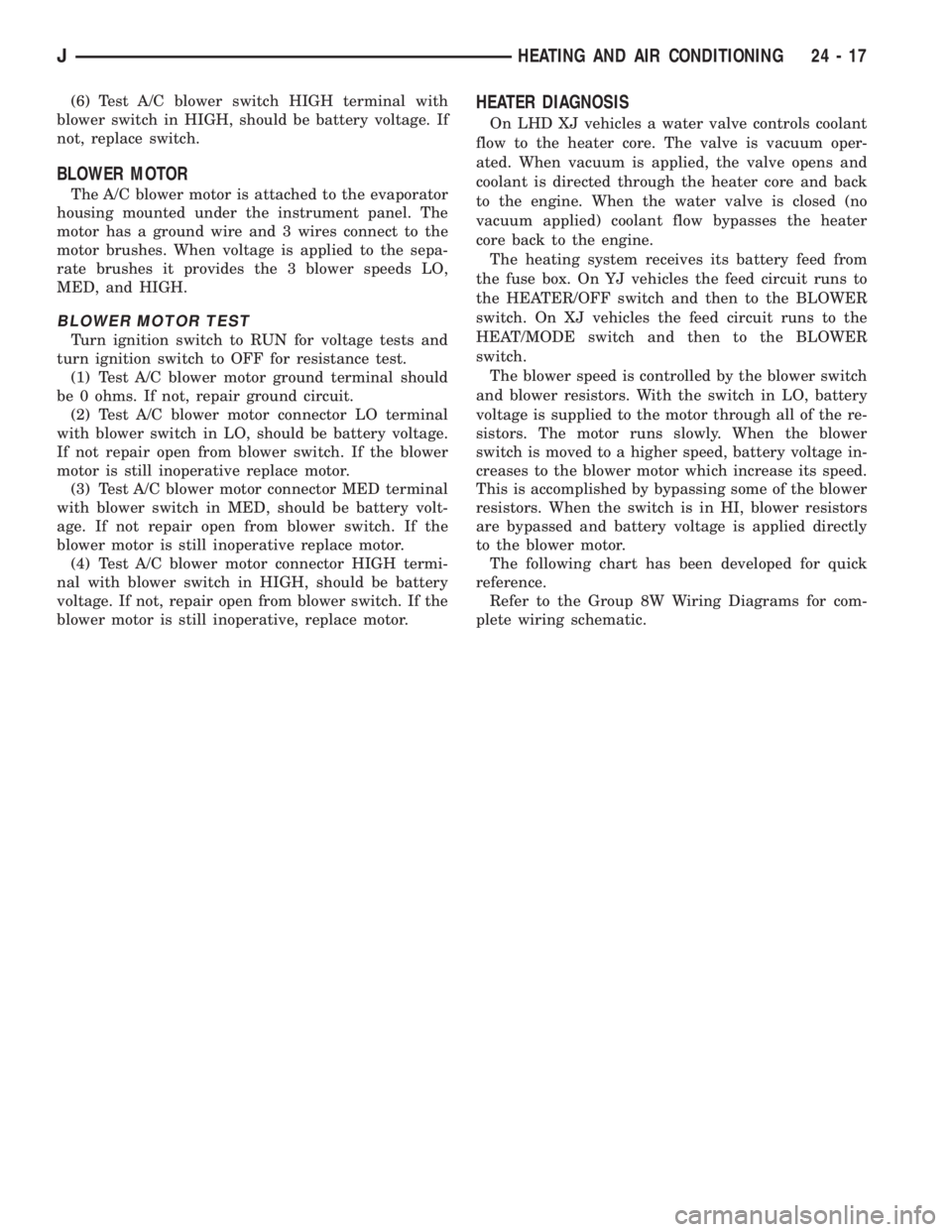
The following chart has been developed for quick
reference.
Refer to the Group 8W Wiring Diagrams for com-
plete wiring schematic.
JHEATING AND AIR CONDITIONING 24 - 17
Page 2132 of 2158
DIAGRAM INDEX; AIR CONDITIONING/
HEATER (XJ-RHD)..................8W-42-2
DIAGRAM INDEX; AIR CONDITIONING/
HEATER (YJ)...............8W-42-1,8W-42-2
DIAGRAM INDEX; ANTI-LOCK BRAKES
(XJ).............................8W-32-3
DIAGRAM INDEX; ANTI-LOCK BRAKES
(XJ-RHD).........................8W-32-3
DIAGRAM INDEX; ANTI-LOCK BRAKES
(YJ).............................8W-32-2
DIAGRAM INDEX; CHARGING SYSTEM
(XJ).............................8W-20-1
DIAGRAM INDEX; CHARGING SYSTEM
(XJ-RHD).........................8W-20-1
DIAGRAM INDEX; CHARGING SYSTEM
(YJ).............................8W-20-1
DIAGRAM INDEX; FRONT LIGHTING (XJ) . 8W-50-2
DIAGRAM INDEX; FRONT LIGHTING
(XJ-RHD).........................8W-50-3
DIAGRAM INDEX; FRONT LIGHTING (YJ) . 8W-50-2
DIAGRAM INDEX; FUEL/IGNITION (YJ) . . 8W-30-5
DIAGRAM INDEX; FUSE/FUSE BLOCK
(XJ).............................8W-10-1
DIAGRAM INDEX; FUSE/FUSE BLOCK
(XJ-RHD).........................8W-10-1
DIAGRAM INDEX; FUSE/FUSE BLOCK
(YJ).............................8W-10-1
DIAGRAM INDEX; GROUND
DISTRIBUTION (XJ)................8W-15-1
DIAGRAM INDEX; GROUND
DISTRIBUTION (XJ-RHD)............8W-15-1
DIAGRAM INDEX; GROUND
DISTRIBUTION (YJ)..................8W-15-1
DIAGRAM INDEX; HEATED REAR
WINDOW (XJ).....................8W-48-1
DIAGRAM INDEX; HEATED REAR
WINDOW (XJ-RHD).................8W-48-1
DIAGRAM INDEX; HEATED REAR
WINDOW (YJ).....................8W-48-1
DIAGRAM INDEX; HORN/CIGAR LIGHTER . . . 8E-1
DIAGRAM INDEX; HORN/CIGAR LIGHTER
(YJ).............................8W-41-1
DIAGRAM INDEX; INSTRUMENT
CLUSTER (XJ).............8W-40-1,8W-40-3
DIAGRAM INDEX; INSTRUMENT
CLUSTER (XJ-RHD)................8W-40-3
DIAGRAM INDEX; INSTRUMENT
CLUSTER (YJ).....................8W-40-2
DIAGRAM INDEX; INTERIOR LIGHTING
(XJ).............................8W-44-2
DIAGRAM INDEX; INTERIOR LIGHTING
(XJ-RHD).........................8W-44-2
DIAGRAM INDEX; INTERIOR LIGHTING
(YJ).............................8W-44-2
DIAGRAM INDEX; OVERHEAD CONSOLE
(XJ).............................8W-49-1
DIAGRAM INDEX; OVERHEAD CONSOLE
(XJ-RHD).........................8W-49-1
DIAGRAM INDEX; POWER DISTRIBUTION
(XJ).............................8W-11-1
DIAGRAM INDEX; POWER DISTRIBUTION
(XJ-RHD).........................8W-11-1
DIAGRAM INDEX; POWER DISTRIBUTION
(YJ).............................8W-11-1
DIAGRAM INDEX; POWER DOOR LOCKS
(XJ)
.............................8W-61-1
DIAGRAM INDEX; POWER DOOR LOCKS
(XJ-RHD)
.........................8W-61-1
DIAGRAM INDEX; POWER MIRRORS
(XJ)
.............................8W-62-1
DIAGRAM INDEX; POWER MIRRORS
(XJ-RHD)
.........................8W-62-1
DIAGRAM INDEX; POWER SEAT (XJ)
. . . 8W-63-1
DIAGRAM INDEX; POWER SEAT
(XJ-RHD)
.........................8W-63-1
DIAGRAM INDEX; POWER WINDOWS
(XJ)
.............................8W-60-2
DIAGRAM INDEX; POWER WINDOWS
(XJ-RHD)
.........................8W-60-2
DIAGRAM INDEX; REAR LIGHTING (XJ)
. 8W-51-1
DIAGRAM INDEX; REAR LIGHTING
(XJ-RHD)
.........................8W-51-1
DIAGRAM INDEX; REAR LIGHTING (YJ)
. 8W-51-1
DIAGRAM INDEX; STARTING SYSTEM
(XJ)
.............................8W-21-1
DIAGRAM INDEX; STARTING SYSTEM
(XJ-RHD)
.........................8W-21-1DIAGRAM INDEX; STARTING SYSTEM
(YJ).............................8W-21-1
DIAGRAM INDEX; TRAILER TOW (XJ) . . 8W-54-1
DIAGRAM INDEX; TRAILER TOW
(XJ-RHD).........................8W-54-1
DIAGRAM INDEX; TRANSMISSION
CONTROLS (XJ)...................8W-31-1
DIAGRAM INDEX; TRANSMISSION
CONTROLS (XJ-RHD)...............8W-31-1
DIAGRAM INDEX; TRANSMISSION
CONTROLS (YJ)...................8W-31-1
DIAGRAM INDEX; TURN SIGNALS (XJ) . 8W-52-1
DIAGRAM INDEX; TURN SIGNALS
(XJ-RHD).........................8W-52-1
DIAGRAM INDEX; TURN SIGNALS (YJ) . 8W-52-1
DIAGRAM INDEX; VEHICLE SPEED
CONTROL (XJ)....................8W-33-1
DIAGRAM INDEX; VEHICLE SPEED
CONTROL (XJ-RHD)................8W-33-1
DIAGRAM INDEX; WIPERS (XJ).......8W-53-2
DIAGRAM INDEX; WIPERS (XJ-RHD) . . . 8W-53-2
DIAGRAM INDEX; WIPERS (YJ).......8W-53-2
DIAGRAM INDEX; FUEL/IGNITION
(XJ-RHD).........................8W-30-5
DIAGRAM INDEXÐ2.5L ENGINE;
FUEL/IGNITION (XJ)................8W-30-6
DIAGRAM INDEXÐ4.0L ENGINE;
FUEL/IGNITION (XJ)................8W-30-6
DIFFERENTIAL AND PINION
MEASUREMENT.......................2-40
DIFFERENTIAL ASSEMBLY; FRONT
SUSPENSION AND AXLE.................2-38
DIFFERENTIAL ASSEMBLY; REAR
SUSPENSION AND AXLES...............3-21
DIFFERENTIAL DISASSEMBLY; FRONT
SUSPENSION AND AXLE................2-35
DIFFERENTIAL DISASSEMBLY; REAR
SUSPENSION AND AXLES...............3-18
DIFFERENTIAL INSTALLATION............2-44
DIFFERENTIAL, LIMITED SLIP............3-10
DIFFERENTIAL MEASUREMENT AND
INSTALLATION........................3-25
DIFFERENTIAL OVERHAUL..............3-46
DIFFERENTIAL REMOVAL; FRONT
SUSPENSION AND AXLE................2-34
DIFFERENTIAL REMOVAL; REAR
SUSPENSION AND AXLES...............3-18
DIFFERENTIAL SERVICE................3-34
DIFFERENTIAL SHIM PACK
MEASUREMENT AND ADJUSTMENT.......2-43
DIFFERENTIAL, TRAC-LOK..............3-45
DIMENSION DATA, VEHICLE.....Intro.-5,Intro.-6
DIMENSIONS, AW-4 VALVE BODY CHECK
BALL.............................21-341
DIMENSIONS, DESIGNATIONS,
LABELS/PLATES, CODES..............Intro.-1
DIMENSIONS, FRAME.............13-13,13-1
DIMMER SWITCH REMOVE/INSTALL,
HEADLAMP OR PANEL................8E-42
DIMMER SWITCH REPLACEMENTÐYJ,
HEADLAMP.........................8L-26
DIMMING MODULE; FRONT LIGHTING
(XJ-RHD).........................8W-50-1
DIODE REPLACEMENT; WIRING
DIAGRAMSÐGENERAL INFORMATION
(XJ)...............................8W-8
DIRECT CLUTCH OVERHAUL...........21-228
DISASSEMBLY AND INSPECTION, VALVE
BODY.............................21-147
DISASSEMBLY AND OVERHAUL,
TRANSFER CASE..............21-289,21-310
DISASSEMBLY AND OVERHAUL,
TRANSMISSION.................21-37,21-5
DISASSEMBLY, CALIPER................5-48
DISASSEMBLY, DIFFERENTIAL; FRONT
SUSPENSION AND AXLE................2-35
DISASSEMBLY, DIFFERENTIAL; REAR
SUSPENSION AND AXLES...............3-18
DISASSEMBLY, TRANSMISSION . . 21-119,21-201
DISASSEMBLYÐCOLUMN OR CONSOLE
SHIFT..............................19-60
DISC AND PLATE THICKNESS, AW-4
CLUTCH...........................21-338
DISC BRAKE ROTOR REFINISHING
........5-53
DISC BRAKE ROTOR RUNOUT
...........5-52
DISC BRAKE ROTOR THICKNESS
.........5-52
DISC BRAKES
........................5-45
DISC BRAKESHOE INSTALLATION
.........5-47DISC BRAKESHOE REMOVAL............5-46
DISC INSTALLATION, CLUTCH COVER.....6-10
DISC REMOVAL, CLUTCH COVER.........6-10
DISC RUNOUT, CLUTCH COVER...........6-3
DISCHARGE (ESD) SENSITIVE DEVICES,
ELECTROSTATIC; WIRING
DIAGRAMSÐGENERAL INFORMATION
(XJ)...............................8W-2
DISCONNECT AXLEÐYJ VEHICLES,
VACUUM............................2-27
DISCONNECT AXLE/SHIFT MOTOR
DIAGNOSIS..........................2-29
DISCONNECT AXLE/SHIFT MOTOR
DIAGNOSIS (CONT'D)..................2-30
DISPLAY, ABS WARNING LIGHT...........5-3
DISPLAY SYMBOLS, INTERNATIONAL
VEHICLE CONTROL..................Intro.-5
DISPLAY SYMBOLS, VEHICLE CONTROL . Intro.-10
DISPOSALÐXJ, LIFTGATE SUPPORT
ROD CYLINDER......................23-63
DISTRIBUTOR.......................8D-19
DISTRIBUTOR CAP....................8D-7
DISTRIBUTOR CAP AND ROTOR,
IGNITION CABLES.....................0-20
DISTRIBUTOR ROTOR.................8D-8
DISTRIBUTORS.......................8D-4
DOME LAMP, CARGO LAMP; INTERIOR
LIGHTING (XJ-RHD)................8W-44-1
DOME LAMP, CARGO LAMP, COURTESY
LAMPS; INTERIOR LIGHTING (XJ).....8W-44-1
DOME LAMP REPLACEMENTÐXJ.........8L-17
DOME LAMPÐXJ....................23-93
DOME LAMPS, COURTESY LAMPS;
INTERIOR LIGHTING (YJ)............8W-44-1
DOME/CARGO LAMP BULB
REPLACEMENTÐYJ VEHICLES,
HARDTOP..........................8L-31
DOME/COURTESY LAMP SERVICE
INFORMATIONÐXJ...................8L-16
DOME/COURTESY LAMP SERVICE
INFORMATIONÐYJ...................8L-31
DOME/COURTESY LAMP TROUBLE
DIAGNOSISÐXJ.....................8L-16
DOME/COURTESY LAMP TROUBLE
DIAGNOSISÐYJ.....................8L-31
DOOR ALIGNMENT ADJUSTMENTÐ
MAJOR............................23-41
DOOR ALIGNMENT ADJUSTMENTÐ
MINOR.............................23-37
DOOR ASSIST HANDLEÐYJ, FULL-
METAL............................23-136
DOOR BUMPERSÐXJ, FUEL FILLER.....23-27
DOOR CONTROL CABLES, VENT.........24-32
DOOR EDGE GUARD/EDGE PROTECTOR
STRIPÐXJ.........................23-54
DOOR EXTERNAL HANDLEÐXJ.........23-48
DOOR FRAME GLASS CHANNEL
REPLACEMENTÐYJ.................23-142
DOOR HINGE/HINGE PIN
REPLACEMENTÐXJ..................23-52
DOOR HINGESÐYJ, FULL-METAL.......23-140
DOOR INSIDE LATCH RELEASE AND
LOCK RODSÐXJ.....................23-50
DOOR JAMB SWITCH, DRIVER'S.....8U-1,8U-2
DOOR KEY LOCK CYLINDERÐXJ........23-47
DOOR KEY LOCK CYLINDERÐYJ,
FULL-METAL.......................23-139
DOOR LATCH ADJUSTMENTÐXJ........23-48
DOOR LATCH EXTERNAL RELEASE
HANDLEÐYJ, FULL-METAL............23-140
DOOR LATCH INSIDE RELEASE AND
LOCK HANDLEÐYJ, FULL-METAL.......23-137
DOOR LATCH STRIKERÐYJ, HALF-
METAL............................23-135
DOOR LATCHÐXJ....................23-49
DOOR LATCHÐYJ, FULL-METAL........23-140
DOOR LOCKS, POWER; POWER DOOR
LOCKS (XJ).......................8W-61-1
DOOR LOCKS, POWER; POWER DOOR
LOCKS (XJ-RHD)
..................8W-61-1
DOOR MIRROR (EXTERNAL)ÐYJ, HALF
METAL
............................23-121
DOOR MOTOR SWITCH REPLACEMENT,
BLOWER MOTOR/AIR
.................24-32
DOOR OPENER STORAGE, REMOTE
GARAGE
............................8C-1
DOOR OPENING WEATHERSTRIP
SEALSÐXJ, DOOR WINDOW GLASS
.....23-55
8 INDEXJ
Description Group-Page Description Group-Page Description Group-Page
Page 2133 of 2158
DOOR REMOVAL/INSTALLATIONÐXJ.....23-35
DOOR RESTRAINT REPLACEMENTÐXJ . . . 23-41
DOOR SERVICEÐYJ, FULL-METAL......23-142
DOOR SPACER BLOCKSÐTWO-DOOR
VEHICLES, FRONT....................23-53
DOOR STATIONARY WINDOW
GLASSÐXJ, REAR...................23-46
DOOR TRIM PANELÐXJ...............23-31
DOOR TRIM PANELÐYJ, FULL-METAL . . . 23-137
DOOR VACUUM MOTOR, FRESH AIR.....24-34
DOOR VACUUM MOTOR REPLACEMENT,
A/C RECIRCULATING..................24-27
DOOR VENT WINDOW GLASSÐYJ,
FULL-METAL.......................23-137
DOOR WATERDAMÐYJ, FULL-METAL . . . 23-137
DOOR WEATHERSTRIP SEAL
REPLACEMENTÐYJ.................23-142
DOOR WEATHERSTRIP SEALSÐYJ,
FULL-METAL.......................23-141
DOOR WINDOW EXTERIOR
MOLDINGSÐXJ.....................23-54
DOOR WINDOW GLASS AND DOOR
OPENING WEATHERSTRIP SEALSÐXJ....23-55
DOOR WINDOW GLASS REGULATOR
HANDLEÐYJ, FULL-METAL............23-136
DOOR WINDOW GLASS REGULATORÐ
XJ, FRONT..........................23-42
DOOR WINDOW GLASS REGULATORÐ
XJ, REAR...........................23-44
DOOR WINDOW GLASS REGULATORÐ
YJ, FULL-METAL....................23-138
DOOR WINDOW GLASSÐXJ, FRONT.....23-43
DOOR WINDOW GLASSÐXJ, REAR......23-45
DOOR WINDOW GLASSÐYJ, FULL-
METAL............................23-139
DOORÐYJ, HALF-METAL SOFT TOP.....23-134
DOUBLE CARDAN (CV)................16-11
DRAG LINK....................19-16,19-20
DRAINING COOLING SYSTEM............7-21
DRAW FUSE, IGNITION-OFF.............8F-1
DRAW, IGNITION-OFF.................8A-10
DRB SCAN TOOL; BRAKES...............5-3
DRB SCAN TOOL; COOLING SYSTEM.......7-5
DRB SCAN TOOL; EMISSION CONTROL
SYSTEMS...........................25-2
DRB SCAN TOOL; FUEL SYSTEM........14-54
DRB SCAN TOOL; IGNITION SYSTEMS....8D-8
DRIERÐ2.5L ENGINES, CONDENSER
FILTER.............................24-27
DRIERÐ4.0L ENGINES, FILTER.........24-28
DRIP RAIL MOLDINGÐXJ.............23-25
DRIVE (4WD) SWITCH, FOUR-WHEEL;
INSTRUMENT CLUSTER (XJ-RHD).....8W-40-2
DRIVE (4WD) SWITCH, FOUR-WHEEL;
TRANSMISSION CONTROLS (XJ-RHD) . . 8W-31-1
DRIVE, AUTOMATIC BELT TENSIONERÐ
XJ MODELS WITH RIGHT HAND..........7-42
DRIVE AXLE ASSEMBLY
REPLACEMENTÐXJ VEHICLES; FRONT
SUSPENSION AND AXLE................2-23
DRIVE AXLE ASSEMBLY
REPLACEMENTÐXJ VEHICLES; REAR
SUSPENSION AND AXLES...........3-14,3-31
DRIVE AXLE ASSEMBLY
REPLACEMENTÐYJ VEHICLES; FRONT
SUSPENSION AND AXLE................2-24
DRIVE AXLE ASSEMBLY
REPLACEMENTÐYJ VEHICLES; REAR
SUSPENSION AND AXLES
...............3-14
DRIVE AXLE, FRONT
....................2-3
DRIVE BELT, ACCESSORY
...............0-21
DRIVE BELT DIAGNOSIS (CONT.),
SERPENTINE
.........................7-40
DRIVE BELT DIAGNOSIS, SERPENTINE
.....7-39
DRIVE, BELT SERVICEÐEXCEPT RIGHT
HAND
...............................7-40
DRIVE, BELT SERVICEÐXJ MODELS
WITH RIGHT HAND
....................7-42
DRIVE BELT TENSION
..................7-45
DRIVE BELTS, ENGINE ACCESSORY
.......7-38
DRIVE GEAR, SPEED SENSOR
ROTORÐSPEEDOMETER
.............21-193
DRIVE, GENERATOR REMOVE/INSTALLÐ
LEFT-HAND
..........................8B-6
DRIVE, GENERATOR REMOVE/INSTALLÐ
RIGHT-HAND
.........................8B-7
DRIVE PULLEY REPLACEMENT
..........19-13DRIVE (RHD), BELT TENSIONÐEXCEPT
RIGHT HAND.........................7-38
DRIVE (RHD), BELT TENSIONÐRIGHT
HAND...............................7-38
DRIVE (RHD) MODELS, BELT TENSIONÐ
EXCEPT RIGHT HAND..................7-45
DRIVE SHAFTS.......................0-26
DRIVE VEHICLES, RIGHT HAND..........23-1
DRIVE, VISCOUS FAN..................7-34
DRIVELINE SNAP; FRONT SUSPENSION
AND AXLE...........................2-19
DRIVELINE SNAP; REAR SUSPENSION
AND AXLES..........................3-10
DRIVELINE VIBRATION.................16-3
DRIVER'S DOOR JAMB SWITCH.....8U-1,8U-2
DRIVER'S POWER LOCK SWITCHÐ2-
DOOR (LHD).........................8P-3
DRIVER'S POWER LOCK SWITCHÐ2-
DOOR (RHD).........................8P-4
DRIVER'S POWER LOCK SWITCHÐ4-
DOOR..............................8P-5
DRIVER'S POWER WINDOW SWITCHÐ
2-DOOR (LHD).......................8S-4
DRIVER'S POWER WINDOW SWITCHÐ
2-DOOR (RHD).......................8S-5
DRIVER'S POWER WINDOW SWITCHÐ
4-DOOR.............................8S-3
DRIVER'S SEAT BELT SWITCH.......8U-1,8U-3
DRIVETRAIN.........................0-22
DRL MODULE REPLACEMENTÐXJ.......8L-15
DRL MODULE REPLACEMENTÐYJ........8L-30
DRUM BRAKE ADJUSTMENT............5-57
DRUM BRAKES.......................5-55
DRUM BRAKESHOE INSTALLATION.......5-55
DRUM BRAKESHOE REMOVAL...........5-55
DRUM REFINISHING, BRAKE............5-58
DRUMÐREAR SUPPORT OVERHAUL,
OVERRUNNING CLUTCHÐLOW-
REVERSE..........................21-125
DUCT, DEFROSTER NOZZLE............24-33
DUCT, FRESH AIR INTAKE..............24-34
ECU AND HCU DIAGNOSIS, ANTILOCK......5-3
ECU INSTALLATION (XJ MODELS)........5-40
ECU OPERATION......................5-37
ECU REMOVAL (XJ MODELS)............5-40
ECU REMOVAL/INSTALLATION (YJ
MODELS)............................5-41
EDGE GUARD/EDGE PROTECTOR
STRIPÐXJ, DOOR....................23-54
EFFECTS OF INCORRECT FLUID LEVEL....21-71
EFFORT, HARD PEDAL OR HIGH PEDAL.....5-6
ELECTRIC COOLING FANÐXJ MODELS
WITH 4.0L 6-CYLINDER ENGINE,
AUXILIARY..........................7-35
ELECTRICAL CONTROL, FUEL PUMP......14-5
ELECTRONIC CONTROL UNIT (ECU).......5-34
ELECTROSTATIC DISCHARGE (ESD)
SENSITIVE DEVICES; WIRING
DIAGRAMSÐGENERAL INFORMATION
(XJ)...............................8W-2
ELEMENT, AIR CLEANER; EMISSION
CONTROL SYSTEMS...................25-7
ELEMENT, AIR CLEANER; FUEL SYSTEM . . 14-59
ELEMENT, AIR CLEANER; LUBRICATION
AND MAINTENANCE...................0-18
ELEMENT TEST, OXYGEN SENSOR (O2S)
HEATING...........................14-48
ELEMENTS, HEATER; POWER MIRRORS
(XJ-RHD).........................8W-62-1
EMISSION CONTROL INFORMATION
(VECI) LABEL, VEHICLE.................25-1
EMISSION CONTROL SYSTEM...........0-20
EMISSION CONTROL SYSTEM
MAINTENANCE........................0-4
EMISSION CONTROLS..................25-4
EMR LAMPÐPCM OUTPUT............14-27
ENGINE ACCESSORY DRIVE BELTS.......7-38
ENGINE AND TRANSMISSION/TRANSFER
CASE IDENTIFICATION...............Intro.-5
ENGINE ASSEMBLY (SHORT BLOCK),
SERVICE.............................9-4
ENGINE ASSEMBLYÐXJ VEHICLES
. . . 9-18,9-59
ENGINE ASSEMBLYÐYJ VEHICLES
. . . 9-20,9-62
ENGINE, AUXILIARY ELECTRIC COOLING
FANÐXJ MODELS WITH 4.0L
6-CYLINDER
.........................7-35
ENGINE BLOCK HEATER
................7-44
ENGINE BREAK-IN
.....................0-15ENGINE COOLANT TEMPERATURE
GAUGE; INSTRUMENT CLUSTER (XJ) . . 8W-40-1
ENGINE COOLANT TEMPERATURE
SENSOR; FUEL SYSTEM...............14-60
ENGINE COOLANT TEMPERATURE
SENSOR; FUEL/IGNITION (XJ)........8W-30-3
ENGINE COOLANT TEMPERATURE
SENSOR; FUEL/IGNITION (YJ)........8W-30-3
ENGINE COOLANT TEMPERATURE
SENSOR; IGNITION SYSTEMS......8D-19,8D-5
ENGINE COOLANT TEMPERATURE
SENSOR; FUEL/IGNITION (XJ-RHD)....8W-30-3
ENGINE COOLANT TEMPERATURE
SENSOR TEST; FUEL SYSTEM..........14-46
ENGINE COOLANT TEMPERATURE
SENSOR TEST; IGNITION SYSTEMS.......8D-9
ENGINE COOLANT TEMPERATURE
SENSORÐPCM INPUT................14-23
ENGINE COOLANT TEMPERATURE
WARNING LAMP; INSTRUMENT
CLUSTER (XJ).....................8W-40-1
ENGINE COOLANT TEMPERATURE
WARNING LAMP; INSTRUMENT
CLUSTER (XJ-RHD)................8W-40-1
ENGINE COOLING SYSTEM..............0-18
ENGINE CYLINDER HEAD...........9-25,9-67
ENGINE CYLINDER HEAD COVER.....9-22,9-64
ENGINE CYLINDER HEAD GASKET
FAILURE DIAGNOSIS....................9-5
ENGINE DAMPER.....................9-17
ENGINE DIAGNOSIS....................9-5
ENGINE, DIAGRAM INDEXÐ2.5L;
FUEL/IGNITION (XJ)..................8W-30-6
ENGINE, DIAGRAM INDEXÐ4.0L;
FUEL/IGNITION (XJ)................8W-30-6
ENGINE, ENGINE EXHAUST MANIFOLDÐ
2.5L................................11-7
ENGINE, ENGINE EXHAUST MANIFOLDÐ
4.0L................................11-7
ENGINE, ENGINE FIRING ORDERÐ2.5L
4-CYLINDER........................8D-32
ENGINE, ENGINE FIRING ORDERÐ4.0L
6-CYLINDER........................8D-32
ENGINE EXHAUST MANIFOLDÐ2.5L
ENGINE.............................11-7
ENGINE EXHAUST MANIFOLDÐ4.0L
ENGINE.............................11-7
ENGINE FIRING ORDERÐ2.5L
4-CYLINDER ENGINE.................8D-32
ENGINE FIRING ORDERÐ4.0L
6-CYLINDER ENGINE.................8D-32
ENGINE, INTAKE MANIFOLDÐ2.5L........11-7
ENGINE, INTAKE MANIFOLDÐ4.0L........11-8
ENGINE MAINTENANCE.................0-15
ENGINE MOUNTÐREAR............9-16,9-57
ENGINE MOUNTSÐFRONT..........9-14,9-56
ENGINE OIL..........................0-15
ENGINE OIL CHANGE AND FILTER
REPLACEMENT.......................0-16
ENGINE OIL FILTER....................0-17
ENGINE OIL PRESSURE.................9-7
ENGINE ONLY, POWER STEERING
PRESSURE SWITCHÐ2.5L.............14-63
ENGINE ONLY, TORQUE CONVERTER
CLUTCH (TCC) SOLENOID AND
RELAYÐ2.5L; TRANSMISSION
CONTROLS (XJ)...................8W-31-1
ENGINE ONLY, TRANSMISSION
CONTROL MODULEÐ4.0L;
TRANSMISSION CONTROLS (XJ)......8W-31-1
ENGINE PERFORMANCE.................9-2
ENGINE SERVICE PROCEDURES, 2.5L.....9-13
ENGINE SERVICE PROCEDURES, 4.0L.....9-55
ENGINE SPECIFICATIONS...........9-52,9-93
ENGINE, VACUUM ROUTING
SCHEMATICÐ2.5L 4 CYLINDER..........25-3
ENGINE, VACUUM ROUTING
SCHEMATICÐ4.0L 6 CYLINDER..........25-3
ENGINES, CONDENSER FILTER
DRIERÐ2.5L........................24-27
ENGINES, CONDENSERÐ4.0L..........24-28
ENGINES, FILTER DRIERÐ4.0L
.........24-28
ENGINES, FUEL USAGE STATEMENTÐ
GAS
................................0-19
ENGLISH/SAE CONVERSION, METRIC
. . Intro.-11
ENTRY MODULE, KEYLESS
.........8P-1,8P-7
ENTRY MODULE, REMOTE KEYLESS;
POWER DOOR LOCKS (XJ)
...........8W-61-1
JINDEX 9
Description Group-Page Description Group-Page Description Group-Page
Page 2138 of 2158
INDEX, DIAGRAM; FRONT LIGHTING
(XJ).............................8W-50-2
INDEX, DIAGRAM; FRONT LIGHTING
(XJ-RHD).........................8W-50-3
INDEX, DIAGRAM; FRONT LIGHTING
(YJ).............................8W-50-2
INDEX, DIAGRAM; FUEL/IGNITION (YJ) . 8W-30-5
INDEX, DIAGRAM; FUSE/FUSE BLOCK
(XJ).............................8W-10-1
INDEX, DIAGRAM; FUSE/FUSE BLOCK
(XJ-RHD).........................8W-10-1
INDEX, DIAGRAM; FUSE/FUSE BLOCK
(YJ).............................8W-10-1
INDEX, DIAGRAM; GROUND
DISTRIBUTION (XJ)................8W-15-1
INDEX, DIAGRAM; GROUND
DISTRIBUTION (XJ-RHD)............8W-15-1
INDEX, DIAGRAM; GROUND
DISTRIBUTION (YJ)................8W-15-1
INDEX, DIAGRAM; HEATED REAR
WINDOW (XJ).....................8W-48-1
INDEX, DIAGRAM; HEATED REAR
WINDOW (XJ-RHD).................8W-48-1
INDEX, DIAGRAM; HEATED REAR
WINDOW (YJ).....................8W-48-1
INDEX, DIAGRAM; HORN/CIGAR
LIGHTER............................8E-1
INDEX, DIAGRAM; HORN/CIGAR
LIGHTER (YJ).....................8W-41-1
INDEX, DIAGRAM; INSTRUMENT
CLUSTER (XJ).............8W-40-1,8W-40-3
INDEX, DIAGRAM; INSTRUMENT
CLUSTER (XJ-RHD)................8W-40-3
INDEX, DIAGRAM; INSTRUMENT
CLUSTER (YJ).....................8W-40-2
INDEX, DIAGRAM; INTERIOR LIGHTING
(XJ).............................8W-44-2
INDEX, DIAGRAM; INTERIOR LIGHTING
(XJ-RHD).........................8W-44-2
INDEX, DIAGRAM; INTERIOR LIGHTING
(YJ).............................8W-44-2
INDEX, DIAGRAM; OVERHEAD CONSOLE
(XJ).............................8W-49-1
INDEX, DIAGRAM; OVERHEAD CONSOLE
(XJ-RHD).........................8W-49-1
INDEX, DIAGRAM; POWER
DISTRIBUTION (XJ)................8W-11-1
INDEX, DIAGRAM; POWER
DISTRIBUTION (XJ-RHD)............8W-11-1
INDEX, DIAGRAM; POWER
DISTRIBUTION (YJ)................8W-11-1
INDEX, DIAGRAM; POWER DOOR LOCKS
(XJ).............................8W-61-1
INDEX, DIAGRAM; POWER DOOR LOCKS
(XJ-RHD).........................8W-61-1
INDEX, DIAGRAM; POWER MIRRORS
(XJ).............................8W-62-1
INDEX, DIAGRAM; POWER MIRRORS
(XJ-RHD).........................8W-62-1
INDEX, DIAGRAM; POWER SEAT (XJ) . . 8W-63-1
INDEX, DIAGRAM; POWER SEAT
(XJ-RHD).........................8W-63-1
INDEX, DIAGRAM; POWER WINDOWS
(XJ).............................8W-60-2
INDEX, DIAGRAM; POWER WINDOWS
(XJ-RHD).........................8W-60-2
INDEX, DIAGRAM; REAR LIGHTING
(XJ).............................8W-51-1
INDEX, DIAGRAM; REAR LIGHTING
(XJ-RHD).........................8W-51-1
INDEX, DIAGRAM; REAR LIGHTING
(YJ).............................8W-51-1
INDEX, DIAGRAM; STARTING SYSTEM
(XJ).............................8W-21-1
INDEX, DIAGRAM; STARTING SYSTEM
(XJ-RHD).........................8W-21-1
INDEX, DIAGRAM; STARTING SYSTEM
(YJ).............................8W-21-1
INDEX, DIAGRAM; TRAILER TOW (XJ) . . 8W-54-1
INDEX, DIAGRAM; TRAILER TOW
(XJ-RHD)
.........................8W-54-1
INDEX, DIAGRAM; TRANSMISSION
CONTROLS (XJ)
...................8W-31-1
INDEX, DIAGRAM; TRANSMISSION
CONTROLS (XJ-RHD)
...............8W-31-1
INDEX, DIAGRAM; TRANSMISSION
CONTROLS (YJ)
...................8W-31-1
INDEX, DIAGRAM; TURN SIGNALS (XJ)
. 8W-52-1INDEX, DIAGRAM; TURN SIGNALS
(XJ-RHD).........................8W-52-1
INDEX, DIAGRAM; TURN SIGNALS (YJ) . 8W-52-1
INDEX, DIAGRAM; VEHICLE SPEED
CONTROL (XJ)....................8W-33-1
INDEX, DIAGRAM; VEHICLE SPEED
CONTROL (XJ-RHD)................8W-33-1
INDEX, DIAGRAM; WIPERS (XJ).......8W-53-2
INDEX, DIAGRAM; WIPERS (XJ-RHD) . . 8W-53-2
INDEX, DIAGRAM; WIPERS (YJ).......8W-53-2
INDEX, DIAGRAM; FUEL/IGNITION
(XJ-RHD).........................8W-30-5
INDEX, GROUP; COOLING SYSTEM.......8E-1
INDEX, GROUP; INSTRUMENT PANEL
AND GAUGES........................8E-1
INDEX, SPLICE; SPLICE INFORMATION
(XJ).............................8W-70-1
INDEX, SPLICE; SPLICE INFORMATION
(XJ-RHD).........................8W-70-1
INDEX, SPLICE; SPLICE INFORMATION
(YJ).............................8W-70-1
INDEXÐ2.5L ENGINE, DIAGRAM......8W-30-6
INDEXÐ4.0L ENGINE, DIAGRAM......8W-30-6
INDICATOR LAMP, CHARGING SYSTEM . 8W-40-3
INDICATOR LAMP, HIGH-BEAM;
INSTRUMENT CLUSTER (XJ).........8W-40-2
INDICATOR LAMP, HIGH-BEAM;
INSTRUMENT CLUSTER (XJ-RHD).....8W-40-2
INDICATOR LAMP (MIL), MALFUNCTION;
FUEL/IGNITION (XJ)................8W-30-5
INDICATOR LAMP (MIL), MALFUNCTION;
FUEL/IGNITION (YJ)................8W-30-5
INDICATOR LAMP (MIL), MALFUNCTION;
INSTRUMENT CLUSTER (XJ).........8W-40-2
INDICATOR LAMP (MIL), MALFUNCTION;
INSTRUMENT CLUSTER (XJ-RHD).....8W-40-1
INDICATOR LAMP (MIL), MALFUNCTION;
FUEL/IGNITION (XJ-RHD)............8W-30-4
INDICATOR LAMPÐPCM OUTPUT,
MALFUNCTION......................14-28
INDICATOR LAMPS.....8E-12,8E-25,8E-32,8E-3
INDICATOR LAMPS, TURN SIGNAL;
INSTRUMENT CLUSTER (XJ).........8W-40-2
INDICATOR LAMPS, TURN SIGNAL;
INSTRUMENT CLUSTER (XJ-RHD).....8W-40-2
INDICATOR (SRI) LAMP, SERVICE
REMINDER..........................25-1
INDICATOR WARNING LAMP, SEAT BELT;
INSTRUMENT CLUSTER (XJ).........8W-40-2
INDICATOR WARNING LAMP, SEAT BELT;
INSTRUMENT CLUSTER (XJ-RHD).....8W-40-2
INDICATORÐPCM OUTPUT, SHIFT.......14-29
INDICATORS, TREAD WEAR.............22-3
INFLATION PRESSURES, TIRE...........22-2
INFORMATIONÐXJ, DOME/COURTESY
LAMP SERVICE......................8L-16
INFORMATIONÐXJ, UNDERHOOD LAMP
SERVICE...........................8L-12
INFORMATIONÐYJ, DOME/COURTESY
LAMP SERVICE......................8L-31
INFORMATIONÐYJ, SOFT TOP SERVICE . 23-127
INFORMATIONÐYJ, UNDERHOOD LAMP
SERVICE...........................8L-28
INITIALIZATION, ABS SYSTEM
POWER-UP..........................5-35
INJECTION (MFI)ÐCOMPONENT
DESCRIPTION/SYSTEM OPERATION,
MULTI-PORT FUEL...................14-19
INJECTION (MFI)ÐCOMPONENT
REMOVAL/INSTALLATION, MULTI-PORT
FUEL..............................14-58
INJECTION (MFI)ÐGENERAL
DIAGNOSIS, MULTI-PORT FUEL.........14-35
INJECTOR DIAGNOSISÐVEHICLE RUNS
ROUGH AND/OR HAS A MISS...........14-52
INJECTOR, FUEL.....................14-60
INJECTOR TEST, FUEL.................14-51
INJECTORS, FUEL; FUEL/IGNITION (XJ) . 8W-30-1
INJECTORS, FUEL; FUEL/IGNITION (YJ) . 8W-30-2
INJECTORS, FUEL; FUEL/IGNITION
(XJ-RHD).........................8W-30-1
INJECTORSÐPCM OUTPUT, FUEL
.......14-27
IN-LINE FUSE
........................8F-1
INNER AXLE SHAFT OIL SEAL
REPLACEMENT
.......................2-35
INNER SCUFF PLATE/COWL SIDE TRIM
PANELÐXJ, FRONT
...................23-86
INNER SPLASH SHIELDSÐYJ, FENDER
. . 23-116INPUT, AIR CONDITIONING (A/C)
CONTROLSÐPCM....................14-21
INPUT, AUTOMATIC SHUTDOWN (ASD)
SENSEÐPCM.......................14-21
INPUT, BATTERY VOLTAGEÐPCM........14-21
INPUT, BRAKE SWITCH; ANTI-LOCK
BRAKES (XJ)......................8W-32-2
INPUT, BRAKE SWITCH; ANTI-LOCK
BRAKES (XJ-RHD).................8W-32-2
INPUT, BRAKE SWITCH; ANTI-LOCK
BRAKES (YJ)......................8W-32-2
INPUT, BRAKE SWITCH; FUEL/IGNITION
(XJ).............................8W-30-5
INPUT, BRAKE SWITCH; FUEL/IGNITION
(YJ).............................8W-30-5
INPUT, BRAKE SWITCH; FUEL/IGNITION
(XJ-RHD).........................8W-30-5
INPUT, BRAKE SWITCHÐPCM..........14-22
INPUT, CAMSHAFT POSITION SENSORÐ
PCM...............................14-22
INPUT, CRANKSHAFT POSITION
SENSORÐPCM......................14-22
INPUT, DATA LINK CONNECTORÐPCM . . . 14-22
INPUT, ENGINE COOLANT
TEMPERATURE SENSORÐPCM.........14-23
INPUT, EXTENDED IDLE SWITCHÐPCM . . . 14-23
INPUT, IGNITION CIRCUIT SENSEÐPCM . . 14-23
INPUT, INTAKE MANIFOLD AIR
TEMPERATURE SENSORÐPCM.........14-22
INPUT, MANIFOLD ABSOLUTE
PRESSURE (MAP) SENSORÐPCM.......14-23
INPUT, OXYGEN (O2S) SENSORÐPCM.....14-24
INPUT, PARK/NEUTRAL SWITCHÐPCM . . . 14-24
INPUT, POWER STEERING PRESSURE
SWITCHÐPCM......................14-24
INPUT, SCI RECEIVEÐPCM............14-24
INPUT, SENSOR RETURNÐPCM.........14-25
INPUT SIGNALS, WHEEL/TIRE SIZE........5-3
INPUT, SPEED CONTROLÐPCM.........14-25
INPUT, THROTTLE POSITION SENSOR
(TPS)ÐPCM........................14-25
INPUT, VEHICLE SPEED SENSORÐPCM . . 14-25
INSERTÐXJ, REAR QUARTER WINDOW
GLASS/REAR QUARTER PLASTIC........23-73
INSIDE LATCH RELEASE AND LOCK
RODSÐXJ, DOOR....................23-50
INSIDE RELEASE AND LOCK HANDLEÐ
YJ, FULL-METAL DOOR LATCH.........23-137
INSPECTION AND ADJUSTMENT,
PRELIMINARY......................21-176
INSPECTION AND DIAGNOSIS CHARTS.....6-4
INSPECTION AND PARK LOCK
COMPONENT OVERHAUL, ADAPTER/
EXTENSION HOUSING................21-127
INSPECTION, CALIPER CLEANING........5-50
INSPECTION (ENGINE OIL LEAKS IN
GENERAL)............................9-6
INSPECTION, GEAR CLEANING..........19-42
INSPECTION, OVERHAUL CLEANING....21-294,
21-318
INSPECTION, PRE-ALIGNMENT............2-6
INSPECTION, RUBBER AND PLASTIC
COMPONENT.........................0-20
INSPECTION, TORQUE CONVERTER
STATOR CLUTCH....................21-199
INSPECTION, TRANSMISSION CASE
CLEANING.........................21-125
INSPECTION, VALVE BODY
DISASSEMBLY......................21-147
INSTALLATION, 30RH/32RH
TRANSMISSION REMOVAL............21-115
INSTALLATION, ACCELERATION SWITCH . . . 5-39
INSTALLATION AND ADJUSTMENT, REAR
WHEEL SENSOR......................5-38
INSTALLATION, AW-4 TRANSMISSION
REMOVAL.........................21-198
INSTALLATION, BRAKE PEDAL...........5-31
INSTALLATION, BRAKELIGHT SWITCH.....5-32
INSTALLATION, CALIPER................5-51
INSTALLATION, CLUTCH COVER AND
DISC...............................6-10
INSTALLATION, CLUTCH HYDRAULIC
LINKAGE
............................6-14
INSTALLATION, CLUTCH PEDAL
..........6-15
INSTALLATION, DIFFERENTIAL
...........2-44
INSTALLATION, DIFFERENTIAL
MEASUREMENT
.......................3-25
INSTALLATION, DISC BRAKESHOE
........5-47
14 INDEXJ
Description Group-Page Description Group-Page Description Group-Page