fuel type JEEP XJ 1995 Service And Owner's Manual
[x] Cancel search | Manufacturer: JEEP, Model Year: 1995, Model line: XJ, Model: JEEP XJ 1995Pages: 2158, PDF Size: 81.9 MB
Page 1413 of 2158
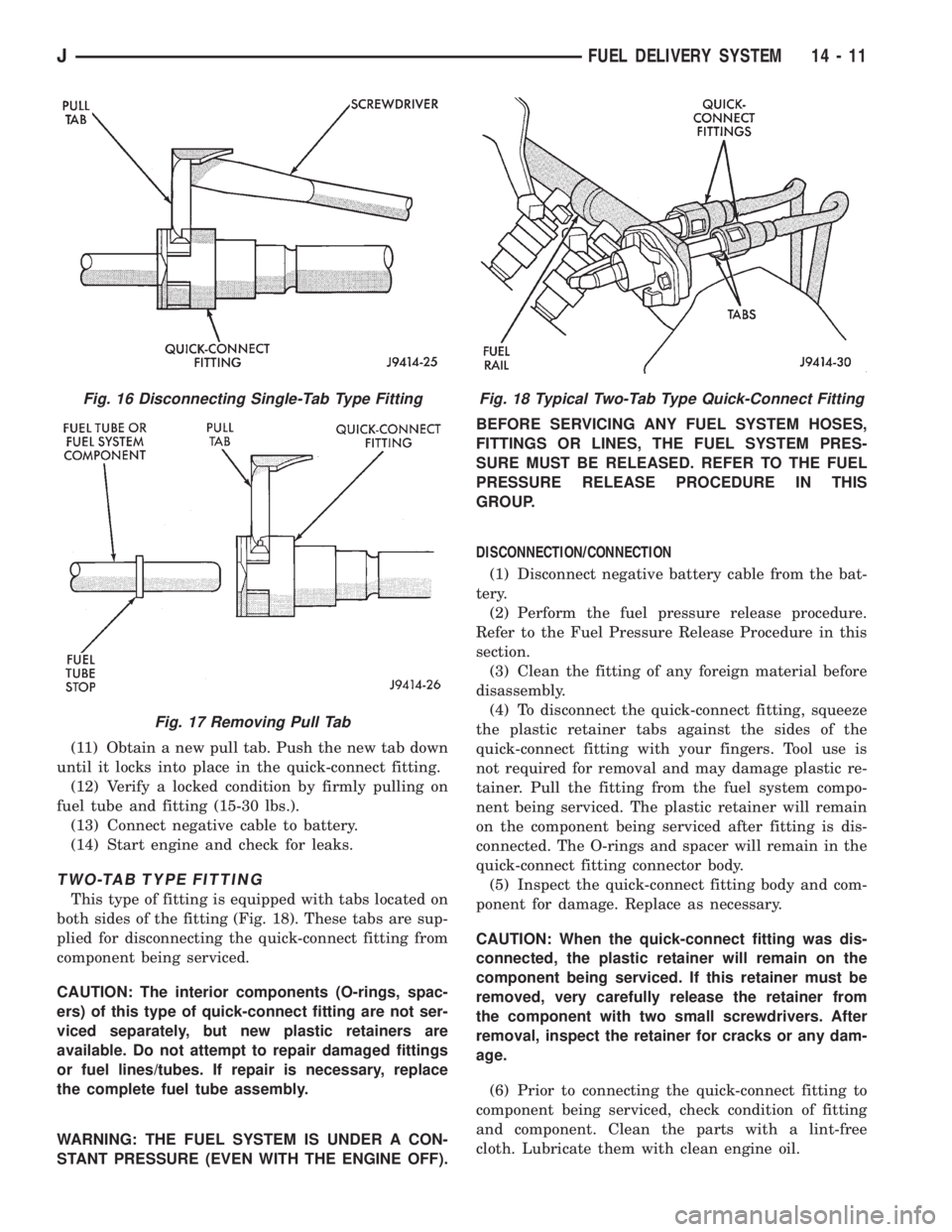
(11) Obtain a new pull tab. Push the new tab down
until it locks into place in the quick-connect fitting.
(12) Verify a locked condition by firmly pulling on
fuel tube and fitting (15-30 lbs.).
(13) Connect negative cable to battery.
(14) Start engine and check for leaks.
TWO-TAB TYPE FITTING
This type of fitting is equipped with tabs located on
both sides of the fitting (Fig. 18). These tabs are sup-
plied for disconnecting the quick-connect fitting from
component being serviced.
CAUTION: The interior components (O-rings, spac-
ers) of this type of quick-connect fitting are not ser-
viced separately, but new plastic retainers are
available. Do not attempt to repair damaged fittings
or fuel lines/tubes. If repair is necessary, replace
the complete fuel tube assembly.
WARNING: THE FUEL SYSTEM IS UNDER A CON-
STANT PRESSURE (EVEN WITH THE ENGINE OFF).BEFORE SERVICING ANY FUEL SYSTEM HOSES,
FITTINGS OR LINES, THE FUEL SYSTEM PRES-
SURE MUST BE RELEASED. REFER TO THE FUEL
PRESSURE RELEASE PROCEDURE IN THIS
GROUP.
DISCONNECTION/CONNECTION
(1) Disconnect negative battery cable from the bat-
tery.
(2) Perform the fuel pressure release procedure.
Refer to the Fuel Pressure Release Procedure in this
section.
(3) Clean the fitting of any foreign material before
disassembly.
(4) To disconnect the quick-connect fitting, squeeze
the plastic retainer tabs against the sides of the
quick-connect fitting with your fingers. Tool use is
not required for removal and may damage plastic re-
tainer. Pull the fitting from the fuel system compo-
nent being serviced. The plastic retainer will remain
on the component being serviced after fitting is dis-
connected. The O-rings and spacer will remain in the
quick-connect fitting connector body.
(5) Inspect the quick-connect fitting body and com-
ponent for damage. Replace as necessary.
CAUTION: When the quick-connect fitting was dis-
connected, the plastic retainer will remain on the
component being serviced. If this retainer must be
removed, very carefully release the retainer from
the component with two small screwdrivers. After
removal, inspect the retainer for cracks or any dam-
age.
(6) Prior to connecting the quick-connect fitting to
component being serviced, check condition of fitting
and component. Clean the parts with a lint-free
cloth. Lubricate them with clean engine oil.
Fig. 16 Disconnecting Single-Tab Type Fitting
Fig. 17 Removing Pull Tab
Fig. 18 Typical Two-Tab Type Quick-Connect Fitting
JFUEL DELIVERY SYSTEM 14 - 11
Page 1414 of 2158
(7) Insert the quick-connect fitting to the compo-
nent being serviced and into the plastic retainer.
When a connection is made, a click will be heard.
(8) Verify a locked condition by firmly pulling on
fuel tube and fitting (15-30 lbs.).
(9) Connect negative cable to battery.
(10) Start engine and check for leaks.
PLASTIC RETAINER RING TYPE FITTING
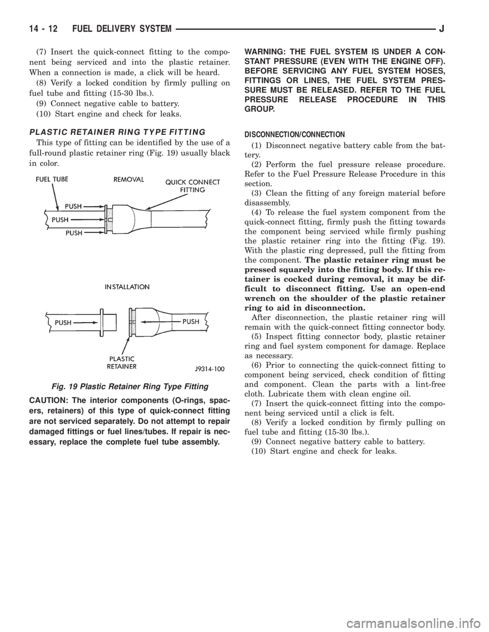
This type of fitting can be identified by the use of a
full-round plastic retainer ring (Fig. 19) usually black
in color.
CAUTION: The interior components (O-rings, spac-
ers, retainers) of this type of quick-connect fitting
are not serviced separately. Do not attempt to repair
damaged fittings or fuel lines/tubes. If repair is nec-
essary, replace the complete fuel tube assembly.WARNING: THE FUEL SYSTEM IS UNDER A CON-
STANT PRESSURE (EVEN WITH THE ENGINE OFF).
BEFORE SERVICING ANY FUEL SYSTEM HOSES,
FITTINGS OR LINES, THE FUEL SYSTEM PRES-
SURE MUST BE RELEASED. REFER TO THE FUEL
PRESSURE RELEASE PROCEDURE IN THIS
GROUP.
DISCONNECTION/CONNECTION
(1) Disconnect negative battery cable from the bat-
tery.
(2) Perform the fuel pressure release procedure.
Refer to the Fuel Pressure Release Procedure in this
section.
(3) Clean the fitting of any foreign material before
disassembly.
(4) To release the fuel system component from the
quick-connect fitting, firmly push the fitting towards
the component being serviced while firmly pushing
the plastic retainer ring into the fitting (Fig. 19).
With the plastic ring depressed, pull the fitting from
the component.The plastic retainer ring must be
pressed squarely into the fitting body. If this re-
tainer is cocked during removal, it may be dif-
ficult to disconnect fitting. Use an open-end
wrench on the shoulder of the plastic retainer
ring to aid in disconnection.
After disconnection, the plastic retainer ring will
remain with the quick-connect fitting connector body.
(5) Inspect fitting connector body, plastic retainer
ring and fuel system component for damage. Replace
as necessary.
(6) Prior to connecting the quick-connect fitting to
component being serviced, check condition of fitting
and component. Clean the parts with a lint-free
cloth. Lubricate them with clean engine oil.
(7) Insert the quick-connect fitting into the compo-
nent being serviced until a click is felt.
(8) Verify a locked condition by firmly pulling on
fuel tube and fitting (15-30 lbs.).
(9) Connect negative battery cable to battery.
(10) Start engine and check for leaks.
Fig. 19 Plastic Retainer Ring Type Fitting
14 - 12 FUEL DELIVERY SYSTEMJ
Page 1415 of 2158
FUEL TANKS
INDEX
page page
Fuel Gauge Sending Unit................... 16
Fuel Tank............................... 13
Fuel Tank Capacities....................... 13
Fuel Tank Filler Tube Cap................... 13Fuel Tank Pressure Relief/Rollover Valve........ 16
General Information....................... 13
Heat Shields............................. 13
No-Lead Fuel Tank Filler Tube................ 13
GENERAL INFORMATION
All XJ and YJ models pass a full 360 degree roll-
over test without fuel leakage. To accomplish this,
fuel and vapor flow controls are required for all fuel
tank connections.
All models are equipped with a pressure relief/roll-
over valve mounted in the top of the fuel tank. The
return line from the fuel pump to the fuel tank con-
tains a one-way check valve.
An evaporative control system prevents raw fuel
vapor from escaping into the atmosphere. Fuel va-
pors from the fuel tank are collected in the EVAP
canister. When the engine is operating, the vapors
are drawn into the intake manifold to be used in
combustion. Refer to Group 25, Emission Control
System for more information.
Inspect all hose/tube connections for completeness.
Be sure that leaks are not present. Replace any hose
that is cracked, scuffed, swelled, has rubbed against
other vehicle components or shows any other sign of
wear that could lead to failure. If it is necessary to
replace a hose, only hose marked EFM/EFI may be
used.
When installing hoses, be sure that they are routed
away from contact with other vehicle components.
The hose clamps used on fuel injected vehicles are
of a special rolled edge construction to prevent the
edge of the clamp from cutting into the hose. Only
these rolled edge type clamps may be used on this
system. Other types of clamps may cut into the hoses
and cause high-pressure fuel leaks.
FUEL TANK CAPACITIES
Refer to the Specifications section at the end of this
group.
NO-LEAD FUEL TANK FILLER TUBE
All vehicles are designed to operate using Unleaded
fuels. The diameter of the opening in the fuel tank
filler neck is sized to only accept unleaded fuel noz-
zles. Gasoline station pumps for unleaded and leaded
fuels have different size nozzles. Leaded fuel nozzles
are larger in diameter than unleaded nozzles. The
fuel tank filler neck opening is also equipped with adeflector, which the smaller unleaded nozzle pushes
back upon entering the filler neck. The deflector will
prevent the larger diameter leaded fuel nozzles from
entering the filler neck and will deflect fuel away
from the filler neck. This happens if filling of the
tank with leaded fuel is attempted.
A label is attached to the instrument panel under
the fuel gauge that reads UNLEADED FUEL ONLY
as a reminder to the driver. A similar label is located
near the fuel tank filler.
FUEL TANK FILLER TUBE CAP
The loss of any fuel or vapor out of the filler neck
is prevented by the use of a safety filler cap. This
will release only under pressure of 10.9 to 13.45 kPa
(1.58 to 1.95 psi). The vacuum release is between .97
and 2.0 kPa (.14 and .29 psi). This cap must be re-
placed by a similar unit if replacement is necessary.
CAUTION: Remove the fuel tank filler tube cap prior
to removing or repairing fuel lines to relieve fuel
tank pressure.
HEAT SHIELDS
The sheet metal heat shields may have to be re-
moved when servicing the fuel tank, fuel lines or va-
por vent line. The heat shields must be installed to
protect the lines and tank from the heat of the ex-
haust system. Refer to Group 11, Exhaust System
and Intake Manifold for proper installation.
FUEL TANK
WARNING: THE FUEL SYSTEM IS UNDER CON-
STANT FUEL PRESSURE (EVEN WITH THE ENGINE
OFF) OF APPROXIMATELY 131-269 KPA (19-39 PSI).
THIS PRESSURE MUST BE RELEASED BEFORE
SERVICING FUEL TANK.
REMOVALÐXJ MODELS
Perform the preceding Fuel System Pressure Re-
lease Procedure.
(1) Disconnect negative battery cable.
JFUEL TANKS 14 - 13
Page 1425 of 2158
The engine will not operate if the PCM does not re-
ceive a crankshaft position sensor input.
ENGINE COOLANT TEMPERATURE SENSORÐPCM
INPUT
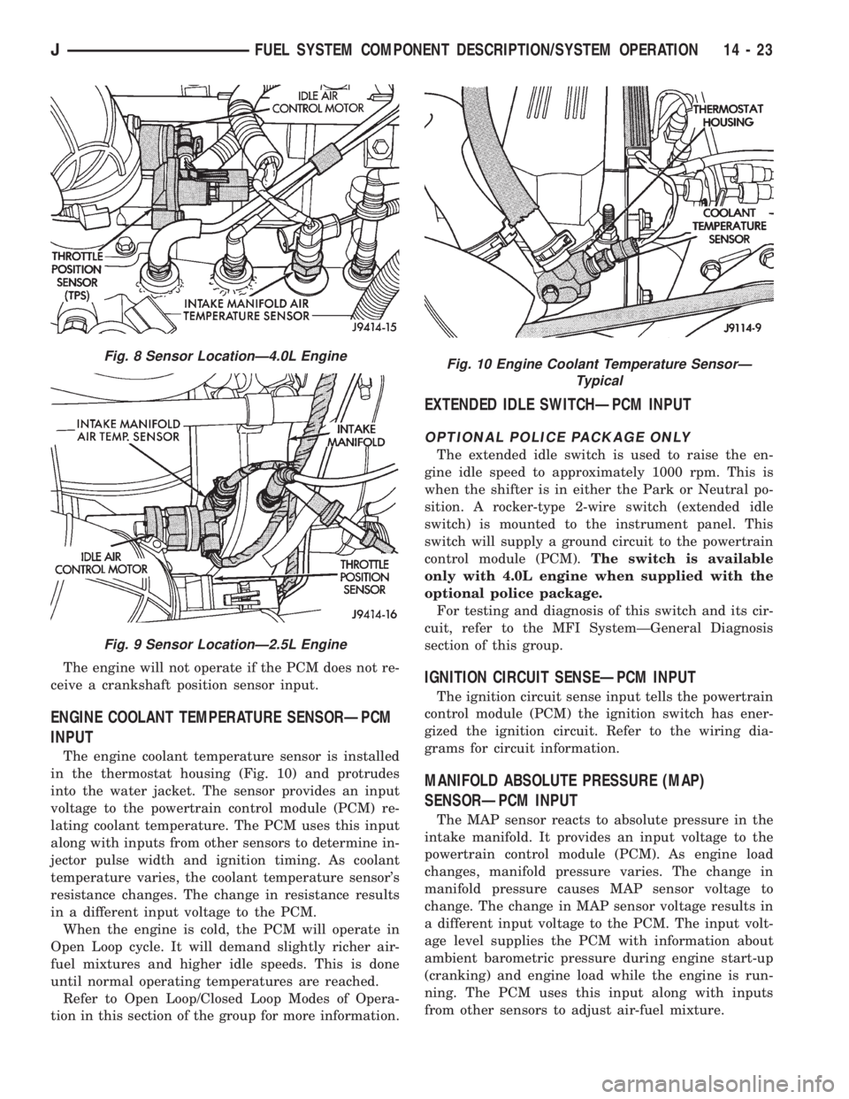
The engine coolant temperature sensor is installed
in the thermostat housing (Fig. 10) and protrudes
into the water jacket. The sensor provides an input
voltage to the powertrain control module (PCM) re-
lating coolant temperature. The PCM uses this input
along with inputs from other sensors to determine in-
jector pulse width and ignition timing. As coolant
temperature varies, the coolant temperature sensor's
resistance changes. The change in resistance results
in a different input voltage to the PCM.
When the engine is cold, the PCM will operate in
Open Loop cycle. It will demand slightly richer air-
fuel mixtures and higher idle speeds. This is done
until normal operating temperatures are reached.
Refer to Open Loop/Closed Loop Modes of Opera-
tion in this section of the group for more information.
EXTENDED IDLE SWITCHÐPCM INPUT
OPTIONAL POLICE PACKAGE ONLY
The extended idle switch is used to raise the en-
gine idle speed to approximately 1000 rpm. This is
when the shifter is in either the Park or Neutral po-
sition. A rocker-type 2-wire switch (extended idle
switch) is mounted to the instrument panel. This
switch will supply a ground circuit to the powertrain
control module (PCM).The switch is available
only with 4.0L engine when supplied with the
optional police package.
For testing and diagnosis of this switch and its cir-
cuit, refer to the MFI SystemÐGeneral Diagnosis
section of this group.
IGNITION CIRCUIT SENSEÐPCM INPUT
The ignition circuit sense input tells the powertrain
control module (PCM) the ignition switch has ener-
gized the ignition circuit. Refer to the wiring dia-
grams for circuit information.
MANIFOLD ABSOLUTE PRESSURE (MAP)
SENSORÐPCM INPUT
The MAP sensor reacts to absolute pressure in the
intake manifold. It provides an input voltage to the
powertrain control module (PCM). As engine load
changes, manifold pressure varies. The change in
manifold pressure causes MAP sensor voltage to
change. The change in MAP sensor voltage results in
a different input voltage to the PCM. The input volt-
age level supplies the PCM with information about
ambient barometric pressure during engine start-up
(cranking) and engine load while the engine is run-
ning. The PCM uses this input along with inputs
from other sensors to adjust air-fuel mixture.
Fig. 8 Sensor LocationÐ4.0L Engine
Fig. 9 Sensor LocationÐ2.5L Engine
Fig. 10 Engine Coolant Temperature SensorÐ
Typical
JFUEL SYSTEM COMPONENT DESCRIPTION/SYSTEM OPERATION 14 - 23
Page 1434 of 2158
²The PCM adjusts ignition timing by increasing
and decreasing spark advance.
²The PCM operates the A/C compressor clutch
through the clutch relay. This happens if A/C has
been selected by the vehicle operator and requested
by the A/C thermostat.
The optional Extended Idle Switch is used to raise
the engine idle speed to approximately 1000 rpm.
This is when the shifter is in either the Park or Neu-
tral position. A rocker-type 2-wire switch (extended
idle switch) is mounted to the instrument panel. This
switch will supply a ground circuit to the powertrain
control module (PCM).The switch is available
only with 4.0L engine when supplied with the
optional police package.
CRUISE MODE
When the engine is at operating temperature, this
is a Closed Loop mode. At cruising speed, the power-
train control module (PCM) receives inputs from:
²Air conditioning select signal (if equipped)
²Air conditioning request signal (if equipped)
²Battery voltage
²Engine coolant temperature sensor
²Crankshaft position sensor
²Intake manifold air temperature sensor
²Manifold absolute pressure (MAP) sensor
²Throttle position sensor (TPS)
²Camshaft position sensor signal (in the distribu-
tor)
²Park/neutral switch (gear indicator signalÐauto.
trans. only)
²Oxygen (O2S) sensor
Based on these inputs, the following occurs:
²Voltage is applied to the fuel injectors with the
PCM. The PCM will then adjust the injector pulse
width by turning the ground circuit to each individ-
ual injector on and off.
²The PCM monitors the O2S sensor input and ad-
justs air-fuel ratio. It also adjusts engine idle speed
through the idle air control (IAC) motor.
²The PCM adjusts ignition timing by turning the
ground path to the coil on and off.
²The PCM operates the A/C compressor clutch
through the clutch relay. This happens if A/C has
been selected by the vehicle operator and requested
by the A/C thermostat.
ACCELERATION MODE
This is an Open Loop mode. The powertrain control
module (PCM) recognizes an abrupt increase in
throttle position or MAP pressure as a demand for
increased engine output and vehicle acceleration. The
PCM increases injector pulse width in response to in-
creased throttle opening.
DECELERATION MODE
When the engine is at operating temperature, this
is an Open Loop mode. During hard deceleration, the
powertrain control module (PCM) receives the follow-
ing inputs.
²Air conditioning select signal (if equipped)
²Air conditioning request signal (if equipped)
²Battery voltage
²Engine coolant temperature sensor
²Crankshaft position sensor
²Intake manifold air temperature sensor
²Manifold absolute pressure (MAP) sensor
²Throttle position sensor (TPS)
²Camshaft position sensor signal (in the distribu-
tor)
²Park/neutral switch (gear indicator signalÐauto.
trans. only)
If the vehicle is under hard deceleration with the
proper rpm and closed throttle conditions, the PCM
will ignore the oxygen sensor input signal. The PCM
will enter a fuel cut-off strategy in which it will not
supply battery voltage to the injectors. If a hard de-
celeration does not exist, the PCM will determine the
proper injector pulse width and continue injection.
Based on the above inputs, the PCM will adjust en-
gine idle speed through the idle air control (IAC) mo-
tor.
The PCM adjusts ignition timing by turning the
ground path to the coil on and off.
The PCM opens the ground circuit to the A/C
clutch relay to disengage the A/C compressor clutch.
This is done until the vehicle is no longer under de-
celeration (if the A/C system is operating).
WIDE OPEN THROTTLE MODE
This is an Open Loop mode. During wide open
throttle operation, the powertrain control module
(PCM) receives the following inputs.
²Battery voltage
²Crankshaft position sensor
²Engine coolant temperature sensor
²Intake manifold air temperature sensor
²Manifold absolute pressure (MAP) sensor
²Throttle position sensor (TPS)
²Camshaft position sensor signal (in the distribu-
tor)
During wide open throttle conditions, the following
occurs:
²Voltage is applied to the fuel injectors with the
powertrain control module (PCM). The PCM will
then control the injection sequence and injector pulse
width by turning the ground circuit to each individ-
ual injector on and off. The PCM ignores the oxygen
sensor input signal and provides a predetermined
amount of additional fuel. This is done by adjusting
injector pulse width.
²The PCM adjusts ignition timing by turning the
ground path to the coil on and off.
14 - 32 FUEL SYSTEM COMPONENT DESCRIPTION/SYSTEM OPERATIONJ
Page 1436 of 2158
The fuel pressure regulator used is a vacuum bal-
anced, nonadjustable type. The regulator is mounted
on the output end of the fuel rail and is connected to
intake manifold vacuum. The fuel return tube (to the
fuel tank) is connected to the fuel pressure regulator.
The regulator is calibrated to maintain fuel system
pressure at approximately 214 kPa (31 psi). This is
with vacuum applied while the engine is at idle. Fuel
pressure will be 55-69 kPa (8-10 psi) higher if vac-
uum is not applied to the regulator.
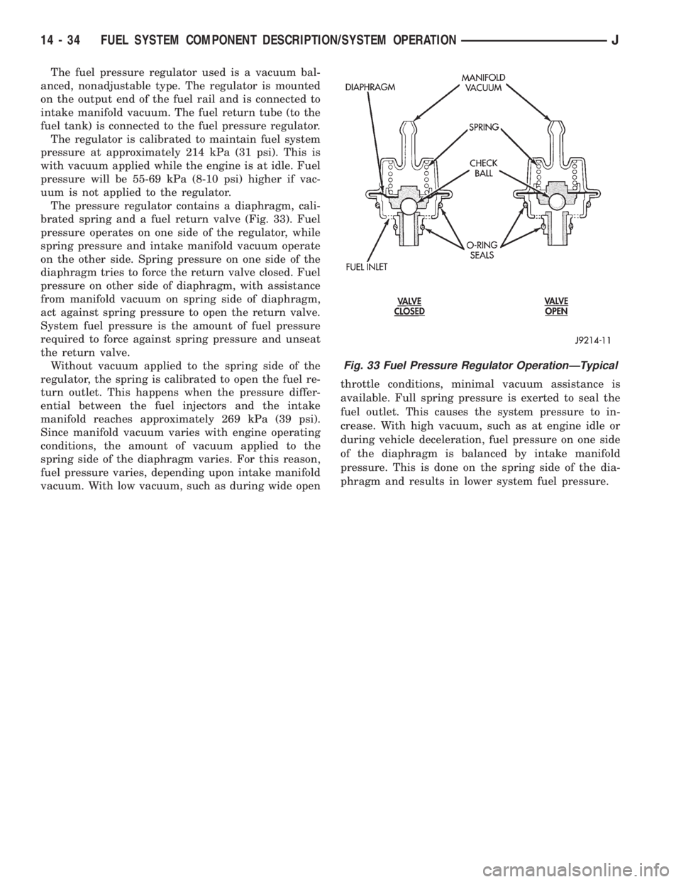
The pressure regulator contains a diaphragm, cali-
brated spring and a fuel return valve (Fig. 33). Fuel
pressure operates on one side of the regulator, while
spring pressure and intake manifold vacuum operate
on the other side. Spring pressure on one side of the
diaphragm tries to force the return valve closed. Fuel
pressure on other side of diaphragm, with assistance
from manifold vacuum on spring side of diaphragm,
act against spring pressure to open the return valve.
System fuel pressure is the amount of fuel pressure
required to force against spring pressure and unseat
the return valve.
Without vacuum applied to the spring side of the
regulator, the spring is calibrated to open the fuel re-
turn outlet. This happens when the pressure differ-
ential between the fuel injectors and the intake
manifold reaches approximately 269 kPa (39 psi).
Since manifold vacuum varies with engine operating
conditions, the amount of vacuum applied to the
spring side of the diaphragm varies. For this reason,
fuel pressure varies, depending upon intake manifold
vacuum. With low vacuum, such as during wide openthrottle conditions, minimal vacuum assistance is
available. Full spring pressure is exerted to seal the
fuel outlet. This causes the system pressure to in-
crease. With high vacuum, such as at engine idle or
during vehicle deceleration, fuel pressure on one side
of the diaphragm is balanced by intake manifold
pressure. This is done on the spring side of the dia-
phragm and results in lower system fuel pressure.
Fig. 33 Fuel Pressure Regulator OperationÐTypical
14 - 34 FUEL SYSTEM COMPONENT DESCRIPTION/SYSTEM OPERATIONJ
Page 1450 of 2158
EXTENDED IDLE SWITCH TEST
OPTIONAL POLICE PACKAGE ONLY
OPERATION
The extended idle switch is used to raise the en-
gine idle speed to approximately 1000 rpm when the
shifter is in either the Park or Neutral position. A
rocker-type 2-wire switch (extended idle switch) is
mounted to the instrument panel.This switch is
available only with 4.0L engine when supplied
with the optional police package.
TESTING
The extended idle switch will control a ground cir-
cuit going to the powertrain control module (PCM).
When a ground signal (through this switch) has been
received at pin number 10 in the PCM, engine idle
speed will increase.
Bring the engine to normal operating temperature
and turn the extended idle switch to the ON position.
Engine speed should now increase to approximately
1000 rpm when the shifter is in either the Park or
Neutral position. If engine speed does not increase,
apply a good ground to pin number 10 at the PCM
using a small paper clip. Be careful not to damage
the wiring with the paper clip. If the engine speed
now increases, it can be assumed that the PCM is
functioning correctly. Check the instrument panel
mounted switch for a closed ground circuit when in
the ON position. If the engine speed will not increase
after applying a ground to pin number 10, replace
the PCM. Refer to Group 8W, Wiring Diagrams for
circuit and wiring information.
THROTTLE POSITION SENSOR (TPS) TEST
To perform a complete test of the sensor and its cir-
cuitry, refer to DRB scan tool and appropriate Pow-
ertrain Diagnostics Procedures manual. To test the
sensor only, refer to the following:
The throttle position sensor (TPS) can be tested
with a digital voltmeter. The center terminal of the
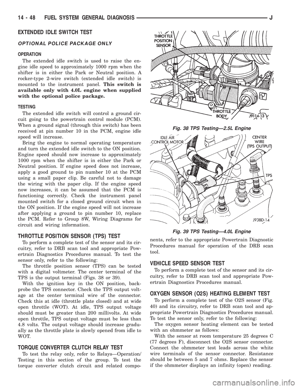
TPS is the output terminal (Figs. 38 or 39).
With the ignition key in the ON position, back-
probe the TPS connector. Check the TPS output volt-
age at the center terminal wire of the connector.
Check this at idle (throttle plate closed) and at wide
open throttle (WOT). At idle, TPS output voltage
should must be greater than 200 millivolts. At wide
open throttle, TPS output voltage must be less than
4.8 volts. The output voltage should increase gradu-
ally as the throttle plate is slowly opened from idle to
WOT.
TORQUE CONVERTER CLUTCH RELAY TEST
To test the relay only, refer to RelaysÐOperation/
Testing in this section of the group. To test the
torque converter clutch circuit and related compo-nents, refer to the appropriate Powertrain Diagnostic
Procedures manual for operation of the DRB scan
tool.
VEHICLE SPEED SENSOR TEST
To perform a complete test of the sensor and its cir-
cuitry, refer to DRB scan tool and appropriate Pow-
ertrain Diagnostics Procedures manual.
OXYGEN SENSOR (O2S) HEATING ELEMENT TEST
To perform a complete test of the O2S sensor (Fig.
40) and its circuitry, refer to DRB scan tool and ap-
propriate Powertrain Diagnostics Procedures manual.
To test the sensor only, refer to the following:
The oxygen sensor heating element can be tested
with an ohmmeter as follows:
With the sensor at room temperature 25 degrees C
(77 degrees F), disconnect the O2S sensor connector.
Connect the ohmmeter test leads across the white
wire terminals of the sensor connector. Resistance
should be between 5 and 7 ohms. Replace the sensor
if the ohmmeter displays an infinity (open) reading.
Fig. 38 TPS TestingÐ2.5L Engine
Fig. 39 TPS TestingÐ4.0L Engine
14 - 48 FUEL SYSTEM GENERAL DIAGNOSISJ
Page 1460 of 2158
MULTI-PORT FUEL INJECTION (MFI)ÐCOMPONENT REMOVAL/INSTALLATION
INDEX
page page
Accelerator Pedal and Throttle Cable........... 58
Air Cleaner Element....................... 59
Air Cleaner Housing....................... 58
Air Conditioning (A/C) Clutch Relay............ 58
Automatic Shutdown (ASD) Relay............. 59
Brake Switch............................ 59
Camshaft Position Sensor................... 60
Crankshaft Position Sensor.................. 60
Engine Coolant Temperature Sensor........... 60
Fuel Filter............................... 60
Fuel Injector............................. 60
Fuel Pressure Regulator.................... 61
Fuel Pump Module........................ 61
Fuel Pump Relay......................... 61
Fuel Rail Assembly........................ 62
Fuel System Pressure Release Procedure....... 62
Fuel Tank Pressure Relief/Rollover Valve........ 62Fuel Tanks.............................. 62
Fuel Tubes/Lines/Hoses and Clamps........... 62
Idle Air Control (IAC) Motor.................. 62
Ignition Coil............................. 62
Intake Manifold........................... 63
Intake Manifold Air Temperature Sensor......... 60
Manifold Absolute Pressure (Map) Sensor....... 63
Oxygen (O2S) Sensor...................... 63
Park Neutral Switch....................... 63
Power Steering Pressure SwitchÐ2.5L
Engine Only............................ 63
Powertrain Control Module (PCM)............. 64
Quick-Connect Fittings..................... 64
Throttle Body............................ 64
Throttle Position Sensor (TPS)............... 65
Torque Converter Clutch Relay............... 65
Vehicle Speed Sensor...................... 66
ACCELERATOR PEDAL AND THROTTLE CABLE
Refer to the Accelerator Pedal and Throttle Cable
section of this group for removal/installation proce-
dures.
AIR CONDITIONING (A/C) CLUTCH RELAY
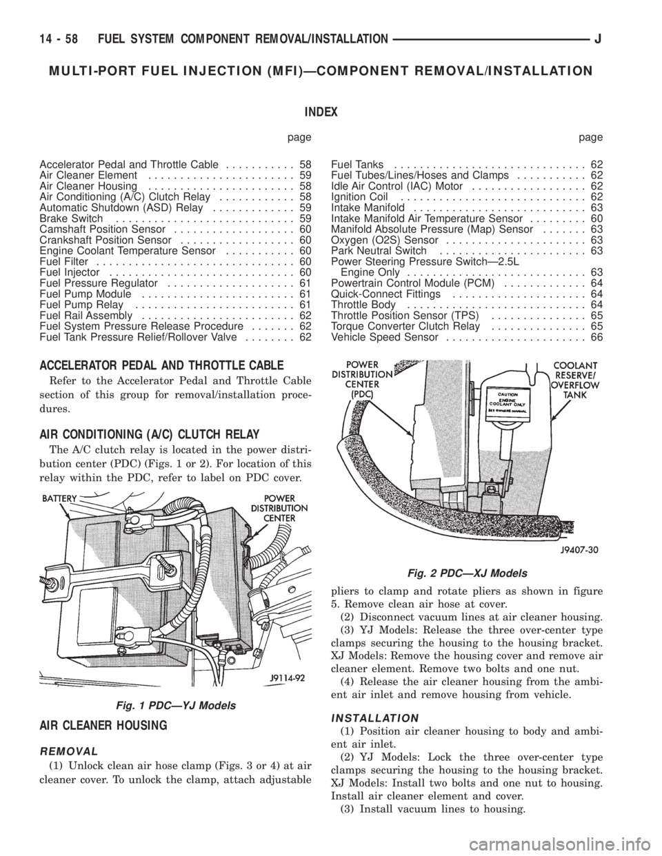
The A/C clutch relay is located in the power distri-
bution center (PDC) (Figs. 1 or 2). For location of this
relay within the PDC, refer to label on PDC cover.
AIR CLEANER HOUSING
REMOVAL
(1) Unlock clean air hose clamp (Figs. 3 or 4) at air
cleaner cover. To unlock the clamp, attach adjustablepliers to clamp and rotate pliers as shown in figure
5. Remove clean air hose at cover.
(2) Disconnect vacuum lines at air cleaner housing.
(3) YJ Models: Release the three over-center type
clamps securing the housing to the housing bracket.
XJ Models: Remove the housing cover and remove air
cleaner element. Remove two bolts and one nut.
(4) Release the air cleaner housing from the ambi-
ent air inlet and remove housing from vehicle.
INSTALLATION
(1) Position air cleaner housing to body and ambi-
ent air inlet.
(2) YJ Models: Lock the three over-center type
clamps securing the housing to the housing bracket.
XJ Models: Install two bolts and one nut to housing.
Install air cleaner element and cover.
(3) Install vacuum lines to housing.
Fig. 1 PDCÐYJ Models
Fig. 2 PDCÐXJ Models
14 - 58 FUEL SYSTEM COMPONENT REMOVAL/INSTALLATIONJ
Page 1908 of 2158
TIRE CHAINS
Tire snow chains may be used on certain models.
Refer to Owner's Manual for more information.
CLEANING OF TIRES
Steam cleaning may be used for cleaning.
DO NOT use gasoline or wire brush for cleaning.
DO NOT use mineral oil or an oil-based solvent.
PRESSURE GAUGES
High-quality, dial-type, air-pressure gauges are rec-
ommended. After checking with the gauge, replace
valve cap and finger tight.
TIRE INFLATION PRESSURES
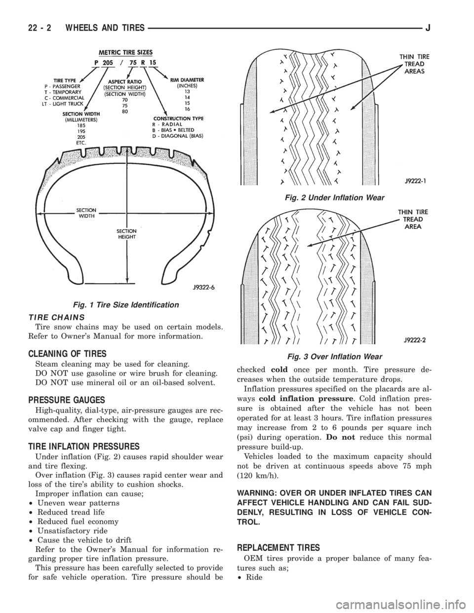
Under inflation (Fig. 2) causes rapid shoulder wear
and tire flexing.
Over inflation (Fig. 3) causes rapid center wear and
loss of the tire's ability to cushion shocks.
Improper inflation can cause;
²Uneven wear patterns
²Reduced tread life
²Reduced fuel economy
²Unsatisfactory ride
²Cause the vehicle to drift
Refer to the Owner's Manual for information re-
garding proper tire inflation pressure.
This pressure has been carefully selected to provide
for safe vehicle operation. Tire pressure should becheckedcoldonce per month. Tire pressure de-
creases when the outside temperature drops.
Inflation pressures specified on the placards are al-
wayscold inflation pressure. Cold inflation pres-
sure is obtained after the vehicle has not been
operated for at least 3 hours. Tire inflation pressures
may increase from 2 to 6 pounds per square inch
(psi) during operation.Do notreduce this normal
pressure build-up.
Vehicles loaded to the maximum capacity should
not be driven at continuous speeds above 75 mph
(120 km/h).
WARNING: OVER OR UNDER INFLATED TIRES CAN
AFFECT VEHICLE HANDLING AND CAN FAIL SUD-
DENLY, RESULTING IN LOSS OF VEHICLE CON-
TROL.
REPLACEMENT TIRES
OEM tires provide a proper balance of many fea-
tures such as;
²Ride
Fig. 1 Tire Size Identification
Fig. 2 Under Inflation Wear
Fig. 3 Over Inflation Wear
22 - 2 WHEELS AND TIRESJ
Page 1996 of 2158
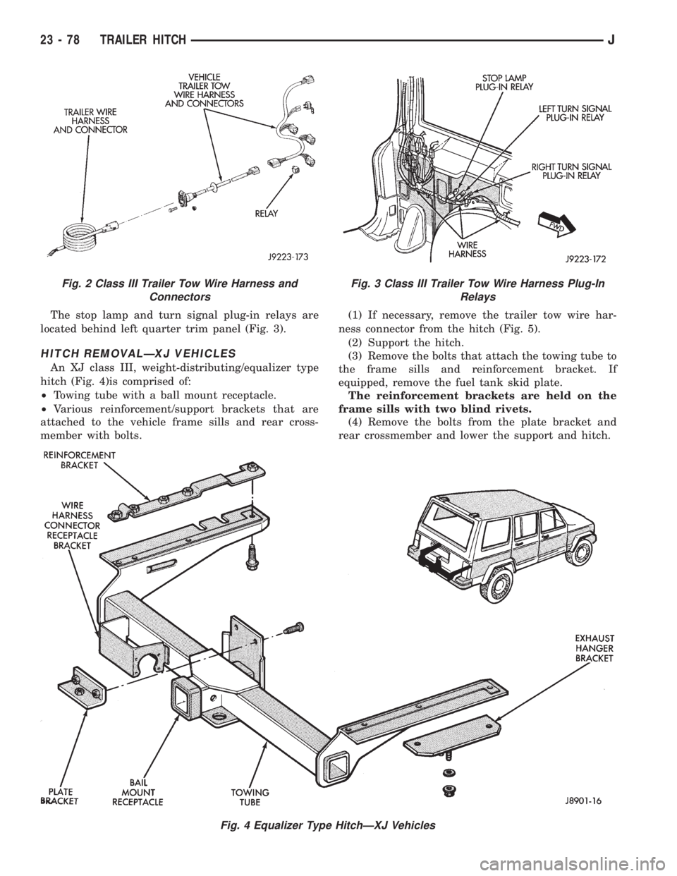
The stop lamp and turn signal plug-in relays are
located behind left quarter trim panel (Fig. 3).
HITCH REMOVALÐXJ VEHICLES
An XJ class III, weight-distributing/equalizer type
hitch (Fig. 4)is comprised of:
²Towing tube with a ball mount receptacle.
²Various reinforcement/support brackets that are
attached to the vehicle frame sills and rear cross-
member with bolts.(1) If necessary, remove the trailer tow wire har-
ness connector from the hitch (Fig. 5).
(2) Support the hitch.
(3) Remove the bolts that attach the towing tube to
the frame sills and reinforcement bracket. If
equipped, remove the fuel tank skid plate.
The reinforcement brackets are held on the
frame sills with two blind rivets.
(4) Remove the bolts from the plate bracket and
rear crossmember and lower the support and hitch.
Fig. 4 Equalizer Type HitchÐXJ Vehicles
Fig. 2 Class III Trailer Tow Wire Harness and
ConnectorsFig. 3 Class III Trailer Tow Wire Harness Plug-In
Relays
23 - 78 TRAILER HITCHJ