oil JEEP XJ 1995 Service And Owner's Guide
[x] Cancel search | Manufacturer: JEEP, Model Year: 1995, Model line: XJ, Model: JEEP XJ 1995Pages: 2158, PDF Size: 81.9 MB
Page 77 of 2158
(17) Tighten the track bar nut at the axle bracket
to 100 Nzm (74 ft. lbs.) torque.
(18) Check the front wheel alignment.
PINION SEAL REPLACEMENT
REMOVAL
(1) Raise and support the vehicle.
(2) Remove wheel and tire assemblies.
(3) Mark the propeller shaft yoke and pinion yoke
for installation alignment reference.
(4) Remove the propeller shaft from the yoke.
(5) Remove the pinion yoke nut and washer. Use
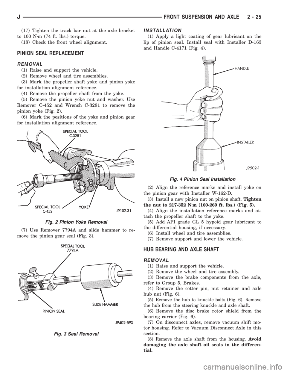
Remover C-452 and Wrench C-3281 to remove the
pinion yoke (Fig. 2).
(6) Mark the positions of the yoke and pinion gear
for installation alignment reference.
(7) Use Remover 7794A and slide hammer to re-
move the pinion gear seal (Fig. 3).
INSTALLATION
(1) Apply a light coating of gear lubricant on the
lip of pinion seal. Install seal with Installer D-163
and Handle C-4171 (Fig. 4).
(2) Align the reference marks and install yoke on
the pinion gear with Installer W-162-D.
(3) Install a new pinion nut on pinion shaft.Tighten
the nut to 217-352 Nzm (160-260 ft. lbs.) (Fig. 5).
(4) Align the installation reference marks and at-
tach the propeller shaft to the yoke.
(5) Add API grade GL 5 hypoid gear lubricant to
the differential housing, if necessary.
(6) Install wheel and tire assemblies.
(7) Remove support and lower the vehicle.
HUB BEARING AND AXLE SHAFT
REMOVAL
(1) Raise and support the vehicle.
(2) Remove the wheel and tire assembly.
(3) Remove the brake components from the axle,
refer to Group 5, Brakes.
(4) Remove the cotter pin, nut retainer and axle
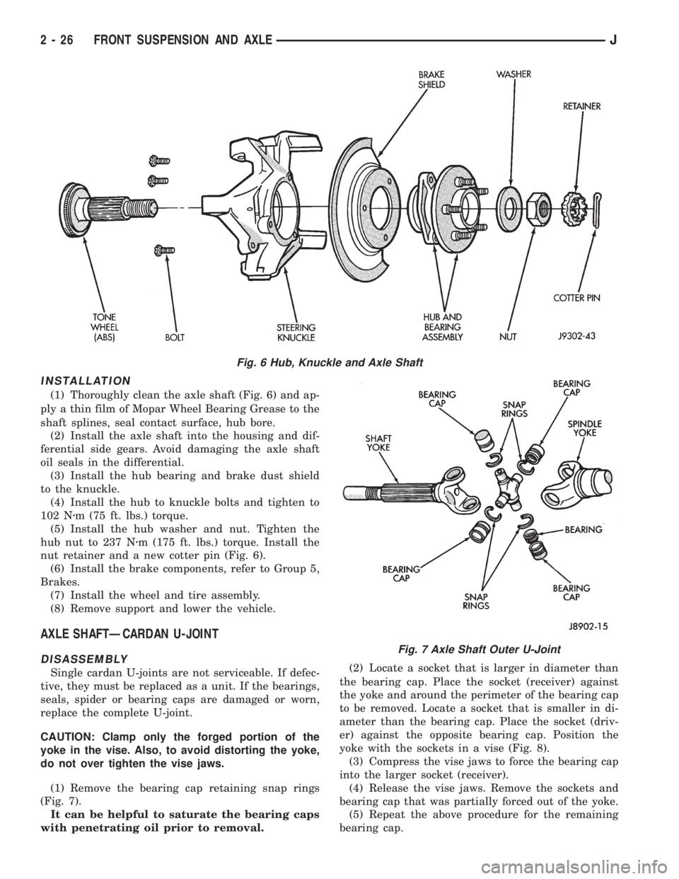
hub nut (Fig. 6).
(5) Remove the hub to knuckle bolts (Fig. 6). Remove
the hub from the steering knuckle and axle shaft.
(6) Remove the disc brake rotor shield from the
bearing carrier (Fig. 6).
(7) On disconnect axles, remove vacuum shift mo-
tor housing. Refer to Vacuum Disconnect Axle in this
section.
(8) Remove the axle shaft from the housing.Avoid
damaging the axle shaft oil seals in the differen-
tial.
Fig. 2 Pinion Yoke Removal
Fig. 3 Seal Removal
Fig. 4 Pinion Seal Installation
JFRONT SUSPENSION AND AXLE 2 - 25
Page 78 of 2158
INSTALLATION
(1) Thoroughly clean the axle shaft (Fig. 6) and ap-
ply a thin film of Mopar Wheel Bearing Grease to the
shaft splines, seal contact surface, hub bore.
(2) Install the axle shaft into the housing and dif-
ferential side gears. Avoid damaging the axle shaft
oil seals in the differential.
(3) Install the hub bearing and brake dust shield
to the knuckle.
(4) Install the hub to knuckle bolts and tighten to
102 Nzm (75 ft. lbs.) torque.
(5) Install the hub washer and nut. Tighten the
hub nut to 237 Nzm (175 ft. lbs.) torque. Install the
nut retainer and a new cotter pin (Fig. 6).
(6) Install the brake components, refer to Group 5,
Brakes.
(7) Install the wheel and tire assembly.
(8) Remove support and lower the vehicle.
AXLE SHAFTÐCARDAN U-JOINT
DISASSEMBLY
Single cardan U-joints are not serviceable. If defec-
tive, they must be replaced as a unit. If the bearings,
seals, spider or bearing caps are damaged or worn,
replace the complete U-joint.
CAUTION: Clamp only the forged portion of the
yoke in the vise. Also, to avoid distorting the yoke,
do not over tighten the vise jaws.
(1) Remove the bearing cap retaining snap rings
(Fig. 7).
It can be helpful to saturate the bearing caps
with penetrating oil prior to removal.(2) Locate a socket that is larger in diameter than
the bearing cap. Place the socket (receiver) against
the yoke and around the perimeter of the bearing cap
to be removed. Locate a socket that is smaller in di-
ameter than the bearing cap. Place the socket (driv-
er) against the opposite bearing cap. Position the
yoke with the sockets in a vise (Fig. 8).
(3) Compress the vise jaws to force the bearing cap
into the larger socket (receiver).
(4) Release the vise jaws. Remove the sockets and
bearing cap that was partially forced out of the yoke.
(5) Repeat the above procedure for the remaining
bearing cap.
Fig. 6 Hub, Knuckle and Axle Shaft
Fig. 7 Axle Shaft Outer U-Joint
2 - 26 FRONT SUSPENSION AND AXLEJ
Page 83 of 2158
SHIFT MOTORÐREMOVAL/DISASSEMBLY
(1) Disconnect the vacuum and wiring connector
from the shift housing.
(2) Remove indicator switch.
(3) Remove the shift motor housing cover, gasket
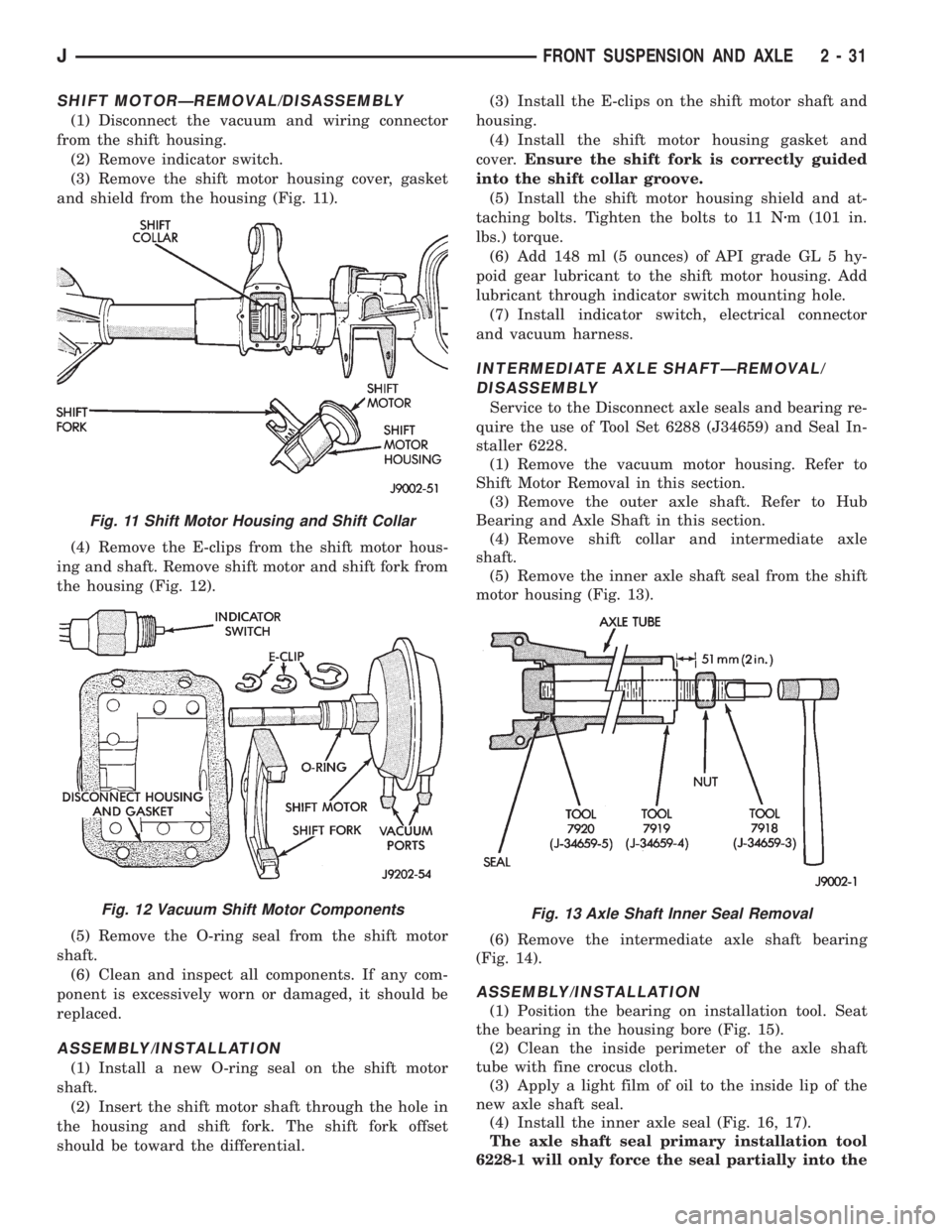
and shield from the housing (Fig. 11).
(4) Remove the E-clips from the shift motor hous-
ing and shaft. Remove shift motor and shift fork from
the housing (Fig. 12).
(5) Remove the O-ring seal from the shift motor
shaft.
(6) Clean and inspect all components. If any com-
ponent is excessively worn or damaged, it should be
replaced.
ASSEMBLY/INSTALLATION
(1) Install a new O-ring seal on the shift motor
shaft.
(2) Insert the shift motor shaft through the hole in
the housing and shift fork. The shift fork offset
should be toward the differential.(3) Install the E-clips on the shift motor shaft and
housing.
(4) Install the shift motor housing gasket and
cover.Ensure the shift fork is correctly guided
into the shift collar groove.
(5) Install the shift motor housing shield and at-
taching bolts. Tighten the bolts to 11 Nzm (101 in.
lbs.) torque.
(6) Add 148 ml (5 ounces) of API grade GL 5 hy-
poid gear lubricant to the shift motor housing. Add
lubricant through indicator switch mounting hole.
(7) Install indicator switch, electrical connector
and vacuum harness.
INTERMEDIATE AXLE SHAFTÐREMOVAL/
DISASSEMBLY
Service to the Disconnect axle seals and bearing re-
quire the use of Tool Set 6288 (J34659) and Seal In-
staller 6228.
(1) Remove the vacuum motor housing. Refer to
Shift Motor Removal in this section.
(3) Remove the outer axle shaft. Refer to Hub
Bearing and Axle Shaft in this section.
(4) Remove shift collar and intermediate axle
shaft.
(5) Remove the inner axle shaft seal from the shift
motor housing (Fig. 13).
(6) Remove the intermediate axle shaft bearing
(Fig. 14).
ASSEMBLY/INSTALLATION
(1) Position the bearing on installation tool. Seat
the bearing in the housing bore (Fig. 15).
(2) Clean the inside perimeter of the axle shaft
tube with fine crocus cloth.
(3) Apply a light film of oil to the inside lip of the
new axle shaft seal.
(4) Install the inner axle seal (Fig. 16, 17).
The axle shaft seal primary installation tool
6228-1 will only force the seal partially into the
Fig. 11 Shift Motor Housing and Shift Collar
Fig. 12 Vacuum Shift Motor ComponentsFig. 13 Axle Shaft Inner Seal Removal
JFRONT SUSPENSION AND AXLE 2 - 31
Page 87 of 2158
(8) Remove the case from housing. Mark or tag
bearing cups indicating which side they were re-
moved. Remove spreader from housing.
INNER AXLE SHAFT OIL SEAL REPLACEMENT
SELECT-TRAC
(1) Remove the inner axle shaft seals with a pry
bay.
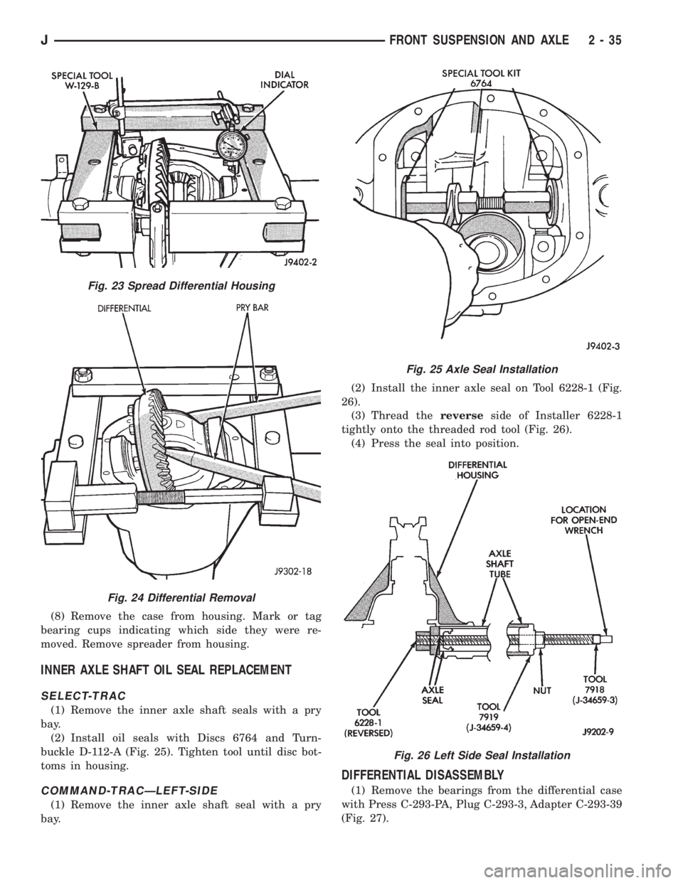
(2) Install oil seals with Discs 6764 and Turn-
buckle D-112-A (Fig. 25). Tighten tool until disc bot-
toms in housing.
COMMAND-TRACÐLEFT-SIDE
(1) Remove the inner axle shaft seal with a pry
bay.(2) Install the inner axle seal on Tool 6228-1 (Fig.
26).
(3) Thread thereverseside of Installer 6228-1
tightly onto the threaded rod tool (Fig. 26).
(4) Press the seal into position.
DIFFERENTIAL DISASSEMBLY
(1) Remove the bearings from the differential case
with Press C-293-PA, Plug C-293-3, Adapter C-293-39
(Fig. 27).
Fig. 23 Spread Differential Housing
Fig. 24 Differential Removal
Fig. 25 Axle Seal Installation
Fig. 26 Left Side Seal Installation
JFRONT SUSPENSION AND AXLE 2 - 35
Page 89 of 2158
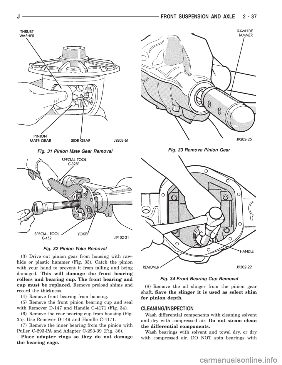
(3) Drive out pinion gear from housing with raw-
hide or plastic hammer (Fig. 33). Catch the pinion
with your hand to prevent it from falling and being
damaged.This will damage the front bearing
rollers and bearing cup. The front bearing and
cup must be replaced.Remove preload shims and
record the thickness.
(4) Remove front bearing from housing.
(5) Remove the front pinion bearing cup and seal
with Remover D-147 and Handle C-4171 (Fig. 34).
(6) Remove the rear bearing cup from housing (Fig.
35). Use Remover D-149 and Handle C-4171.
(7) Remove the inner bearing from the pinion with
Puller C-293-PA and Adapter C-293-39 (Fig. 36).
Place adapter rings so they do not damage
the bearing cage.(8) Remove the oil slinger from the pinion gear
shaft.Save the slinger it is used as select shim
for pinion depth.
CLEANING/INSPECTION
Wash differential components with cleaning solvent
and dry with compressed air.Do not steam clean
the differential components.
Wash bearings with solvent and towel dry, or dry
with compressed air. DO NOT spin bearings with
Fig. 31 Pinion Mate Gear Removal
Fig. 32 Pinion Yoke Removal
Fig. 33 Remove Pinion Gear
Fig. 34 Front Bearing Cup Removal
JFRONT SUSPENSION AND AXLE 2 - 37
Page 90 of 2158
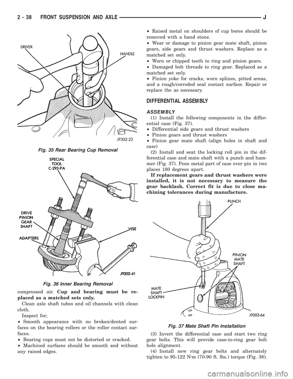
compressed air.Cup and bearing must be re-
placed as a matched sets only.
Clean axle shaft tubes and oil channels with clean
cloth.
Inspect for;
²Smooth appearance with no broken/dented sur-
faces on the bearing rollers or the roller contact sur-
faces.
²Bearing cups must not be distorted or cracked.
²Machined surfaces should be smooth and without
any raised edges.²Raised metal on shoulders of cup bores should be
removed with a hand stone.
²Wear or damage to pinion gear mate shaft, pinion
gears, side gears and thrust washers. Replace as a
matched set only.
²Worn or chipped teeth to ring and pinion gears.
²Damaged bolt threads to ring gear. Replaced as a
matched set only.
²Pinion yoke for cracks, worn splines, pitted areas,
and a rough/corroded seal contact surface. Repair or
replace the as necessary.
DIFFERENTIAL ASSEMBLY
ASSEMBLY
(1) Install the following components in the differ-
ential case (Fig. 37).
²Differential side gears and thrust washers
²Pinion gears and thrust washers
²Pinion gear mate shaft (align holes in shaft and
case)
(2) Install and seat the locking roll pin in the dif-
ferential case and mate shaft with a punch and ham-
mer (Fig. 37). Peen metal part of case over pin in two
places 180 degrees apart.
If replacement gears and thrust washers were
installed, it is not necessary to measure the
gear backlash. Correct fit is due to close ma-
chining tolerances during manufacture.
(3) Invert the differential case and start two ring
gear bolts. This will provide case-to-ring gear bolt
hole alignment.
(4) Install new ring gear bolts and alternately
tighten to 95-122 Nzm (70-90 ft. lbs.) torque (Fig. 38).
Fig. 35 Rear Bearing Cup Removal
Fig. 36 Inner Bearing Removal
Fig. 37 Mate Shaft Pin Installation
2 - 38 FRONT SUSPENSION AND AXLEJ
Page 91 of 2158
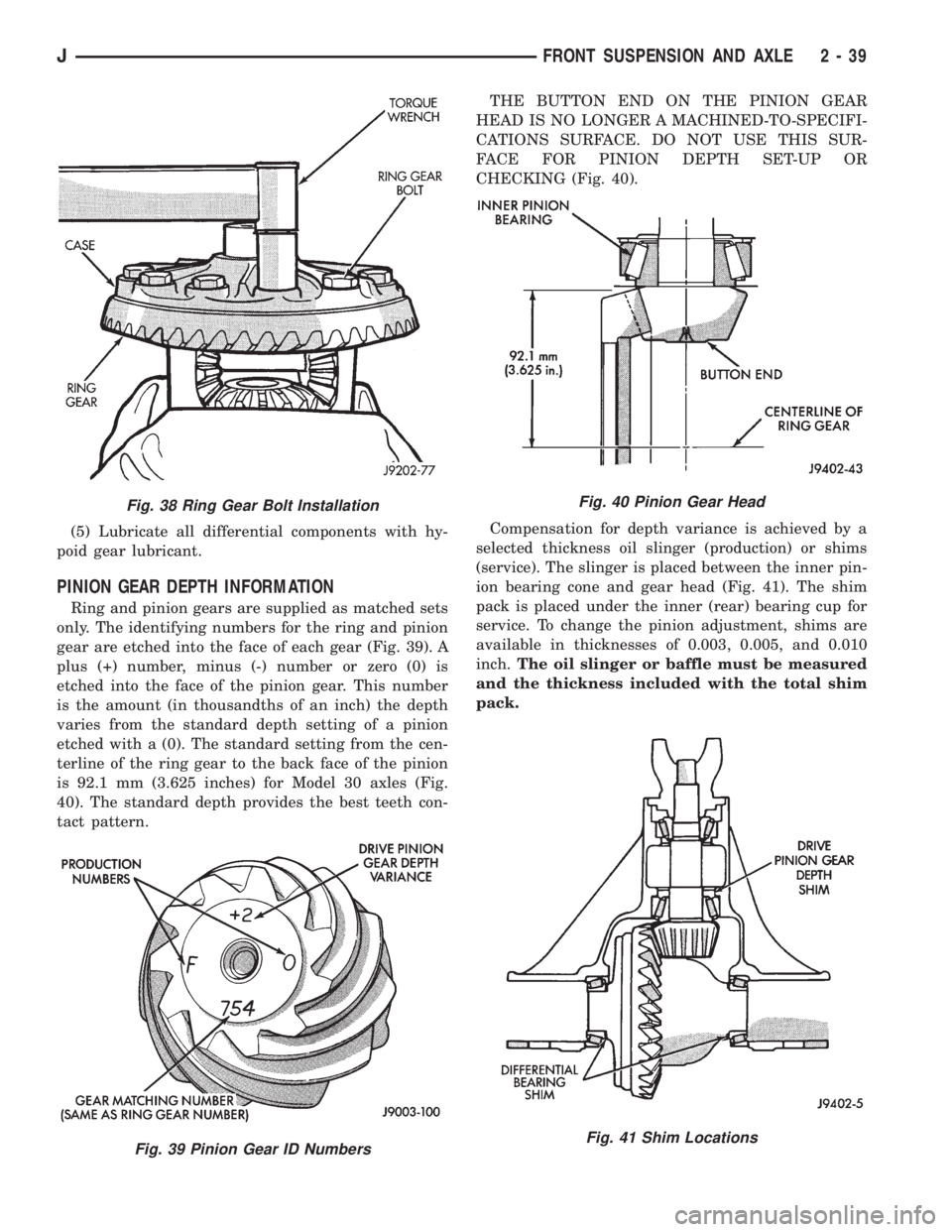
(5) Lubricate all differential components with hy-
poid gear lubricant.
PINION GEAR DEPTH INFORMATION
Ring and pinion gears are supplied as matched sets
only. The identifying numbers for the ring and pinion
gear are etched into the face of each gear (Fig. 39). A
plus (+) number, minus (-) number or zero (0) is
etched into the face of the pinion gear. This number
is the amount (in thousandths of an inch) the depth
varies from the standard depth setting of a pinion
etched with a (0). The standard setting from the cen-
terline of the ring gear to the back face of the pinion
is 92.1 mm (3.625 inches) for Model 30 axles (Fig.
40). The standard depth provides the best teeth con-
tact pattern.THE BUTTON END ON THE PINION GEAR
HEAD IS NO LONGER A MACHINED-TO-SPECIFI-
CATIONS SURFACE. DO NOT USE THIS SUR-
FACE FOR PINION DEPTH SET-UP OR
CHECKING (Fig. 40).
Compensation for depth variance is achieved by a
selected thickness oil slinger (production) or shims
(service). The slinger is placed between the inner pin-
ion bearing cone and gear head (Fig. 41). The shim
pack is placed under the inner (rear) bearing cup for
service. To change the pinion adjustment, shims are
available in thicknesses of 0.003, 0.005, and 0.010
inch.The oil slinger or baffle must be measured
and the thickness included with the total shim
pack.
Fig. 38 Ring Gear Bolt Installation
Fig. 39 Pinion Gear ID Numbers
Fig. 40 Pinion Gear Head
Fig. 41 Shim Locations
JFRONT SUSPENSION AND AXLE 2 - 39
Page 94 of 2158
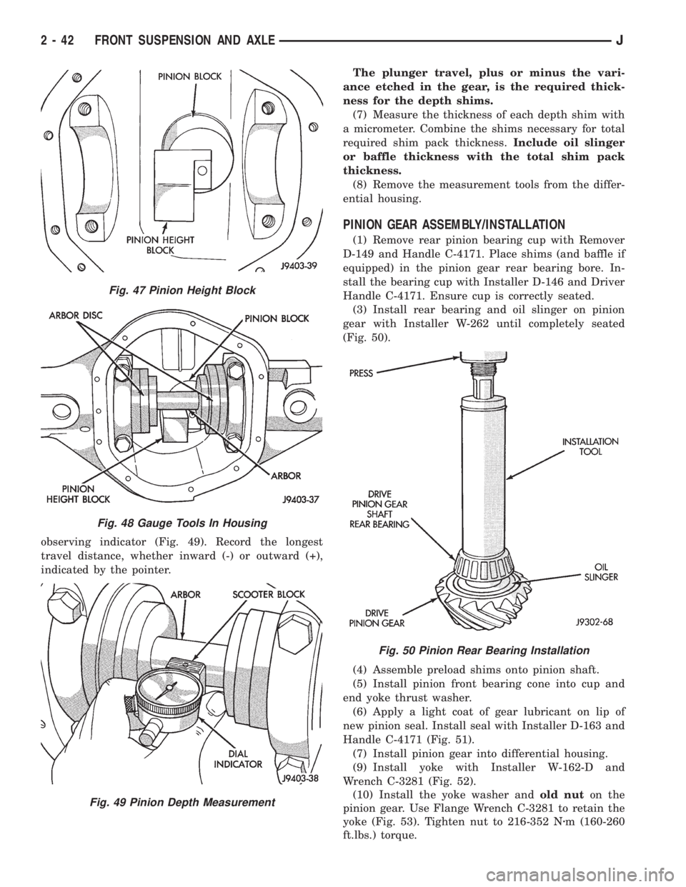
observing indicator (Fig. 49). Record the longest
travel distance, whether inward (-) or outward (+),
indicated by the pointer.The plunger travel, plus or minus the vari-
ance etched in the gear, is the required thick-
ness for the depth shims.
(7) Measure the thickness of each depth shim with
a micrometer. Combine the shims necessary for total
required shim pack thickness.Include oil slinger
or baffle thickness with the total shim pack
thickness.
(8) Remove the measurement tools from the differ-
ential housing.
PINION GEAR ASSEMBLY/INSTALLATION
(1) Remove rear pinion bearing cup with Remover
D-149 and Handle C-4171. Place shims (and baffle if
equipped) in the pinion gear rear bearing bore. In-
stall the bearing cup with Installer D-146 and Driver
Handle C-4171. Ensure cup is correctly seated.
(3) Install rear bearing and oil slinger on pinion
gear with Installer W-262 until completely seated
(Fig. 50).
(4) Assemble preload shims onto pinion shaft.
(5) Install pinion front bearing cone into cup and
end yoke thrust washer.
(6) Apply a light coat of gear lubricant on lip of
new pinion seal. Install seal with Installer D-163 and
Handle C-4171 (Fig. 51).
(7) Install pinion gear into differential housing.
(9) Install yoke with Installer W-162-D and
Wrench C-3281 (Fig. 52).
(10) Install the yoke washer andold nuton the
pinion gear. Use Flange Wrench C-3281 to retain the
yoke (Fig. 53). Tighten nut to 216-352 Nzm (160-260
ft.lbs.) torque.
Fig. 47 Pinion Height Block
Fig. 48 Gauge Tools In Housing
Fig. 49 Pinion Depth Measurement
Fig. 50 Pinion Rear Bearing Installation
2 - 42 FRONT SUSPENSION AND AXLEJ
Page 104 of 2158
XJ SUSPENSION
INDEX
page page
Leaf Spring............................... 4
Leaf Spring Eye Bushing Replacement.......... 5
Shock Absorber........................... 4Spring and Shock Diagnosis.................. 3
Stabilizer Bar............................. 5
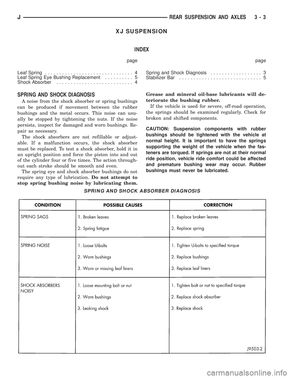
SPRING AND SHOCK DIAGNOSIS
A noise from the shock absorber or spring bushings
can be produced if movement between the rubber
bushings and the metal occurs. This noise can usu-
ally be stopped by tightening the nuts. If the noise
persists, inspect for damaged and worn bushings. Re-
pair as necessary.
The shock absorbers are not refillable or adjust-
able. If a malfunction occurs, the shock absorber
must be replaced. To test a shock absorber, hold it in
an upright position and force the piston into and out
of the cylinder four or five times. The action through-
out each stroke should be smooth and even.
The spring eye and shock absorber bushings do not
require any type of lubrication.Do not attempt to
stop spring bushing noise by lubricating them.Grease and mineral oil-base lubricants will de-
teriorate the bushing rubber.
If the vehicle is used for severe, off-road operation,
the springs should be examined regularly. Check for
broken and shifted components.
CAUTION: Suspension components with rubber
bushings should be tightened with the vehicle at
normal height. It is important to have the springs
supporting the weight of the vehicle when the fas-
teners are torqued. If springs are not at their normal
ride position, vehicle ride comfort could be affected
and premature bushing wear may occur. Rubber
bushings must never be lubricated.
SPRING AND SHOCK ABSORBER DIAGNOSIS
JREAR SUSPENSION AND AXLES 3 - 3
Page 107 of 2158
YJ SUSPENSION
INDEX
page page
Leaf Spring............................... 7
Leaf Spring Eye Bushing Replacement.......... 7
Shock Absorber........................... 7Spring and Shock Diagnosis.................. 6
Track Bar................................ 8
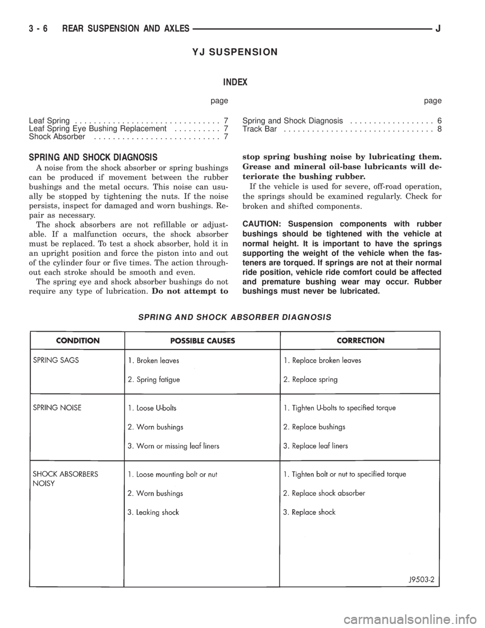
SPRING AND SHOCK DIAGNOSIS
A noise from the shock absorber or spring bushings
can be produced if movement between the rubber
bushings and the metal occurs. This noise can usu-
ally be stopped by tightening the nuts. If the noise
persists, inspect for damaged and worn bushings. Re-
pair as necessary.
The shock absorbers are not refillable or adjust-
able. If a malfunction occurs, the shock absorber
must be replaced. To test a shock absorber, hold it in
an upright position and force the piston into and out
of the cylinder four or five times. The action through-
out each stroke should be smooth and even.
The spring eye and shock absorber bushings do not
require any type of lubrication.Do not attempt tostop spring bushing noise by lubricating them.
Grease and mineral oil-base lubricants will de-
teriorate the bushing rubber.
If the vehicle is used for severe, off-road operation,
the springs should be examined regularly. Check for
broken and shifted components.
CAUTION: Suspension components with rubber
bushings should be tightened with the vehicle at
normal height. It is important to have the springs
supporting the weight of the vehicle when the fas-
teners are torqued. If springs are not at their normal
ride position, vehicle ride comfort could be affected
and premature bushing wear may occur. Rubber
bushings must never be lubricated.
SPRING AND SHOCK ABSORBER DIAGNOSIS
3 - 6 REAR SUSPENSION AND AXLESJ