Cylinder Head JEEP XJ 1995 Service And Repair Manual
[x] Cancel search | Manufacturer: JEEP, Model Year: 1995, Model line: XJ, Model: JEEP XJ 1995Pages: 2158, PDF Size: 81.9 MB
Page 50 of 2158
(5) Inspect the reservoir rubber diaphragm seal for
cracks, cuts and distortion.
(6) Inspect the brake fluid tubing fittings and the
master cylinder housing for indications of fluid leak-
age. Repair as necessary.
(7) Install the brake fluid reservoir cover.
ANTI-LOCK BRAKE SYSTEMÐXJ VEHICLES
The anti-lock brake system fluid reservoir for XJ
Vehicles is located in the engine compartment at the
left side of the dash panel.
(1) Turn the ignition switch ON and allow the
pump motor to operate until it automatically de-en-
ergizes.
(2) Clean the cover before removing it.
CAUTION: Over-filling could cause fluid overflow
and possible reservoir damage when the pump mo-
tor energizes.
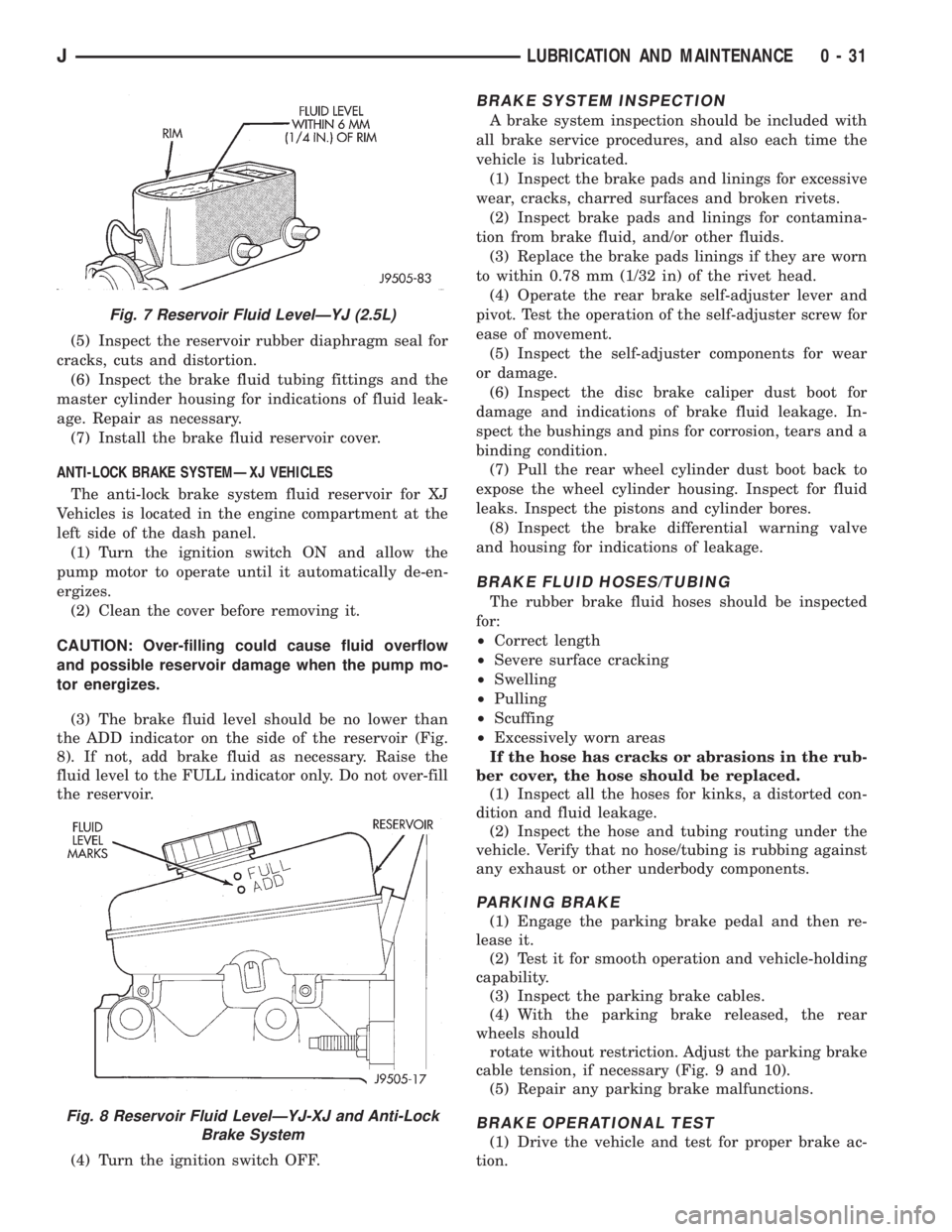
(3) The brake fluid level should be no lower than
the ADD indicator on the side of the reservoir (Fig.
8). If not, add brake fluid as necessary. Raise the
fluid level to the FULL indicator only. Do not over-fill
the reservoir.
(4) Turn the ignition switch OFF.
BRAKE SYSTEM INSPECTION
A brake system inspection should be included with
all brake service procedures, and also each time the
vehicle is lubricated.
(1) Inspect the brake pads and linings for excessive
wear, cracks, charred surfaces and broken rivets.
(2) Inspect brake pads and linings for contamina-
tion from brake fluid, and/or other fluids.
(3) Replace the brake pads linings if they are worn
to within 0.78 mm (1/32 in) of the rivet head.
(4) Operate the rear brake self-adjuster lever and
pivot. Test the operation of the self-adjuster screw for
ease of movement.
(5) Inspect the self-adjuster components for wear
or damage.
(6) Inspect the disc brake caliper dust boot for
damage and indications of brake fluid leakage. In-
spect the bushings and pins for corrosion, tears and a
binding condition.
(7) Pull the rear wheel cylinder dust boot back to
expose the wheel cylinder housing. Inspect for fluid
leaks. Inspect the pistons and cylinder bores.
(8) Inspect the brake differential warning valve
and housing for indications of leakage.
BRAKE FLUID HOSES/TUBING
The rubber brake fluid hoses should be inspected
for:
²Correct length
²Severe surface cracking
²Swelling
²Pulling
²Scuffing
²Excessively worn areas
If the hose has cracks or abrasions in the rub-
ber cover, the hose should be replaced.
(1) Inspect all the hoses for kinks, a distorted con-
dition and fluid leakage.
(2) Inspect the hose and tubing routing under the
vehicle. Verify that no hose/tubing is rubbing against
any exhaust or other underbody components.
PARKING BRAKE
(1) Engage the parking brake pedal and then re-
lease it.
(2) Test it for smooth operation and vehicle-holding
capability.
(3) Inspect the parking brake cables.
(4) With the parking brake released, the rear
wheels should
rotate without restriction. Adjust the parking brake
cable tension, if necessary (Fig. 9 and 10).
(5) Repair any parking brake malfunctions.
BRAKE OPERATIONAL TEST
(1) Drive the vehicle and test for proper brake ac-
tion.
Fig. 7 Reservoir Fluid LevelÐYJ (2.5L)
Fig. 8 Reservoir Fluid LevelÐYJ-XJ and Anti-Lock
Brake System
JLUBRICATION AND MAINTENANCE 0 - 31
Page 262 of 2158
WARNING: HOT, PRESSURIZED COOLANT CAN
CAUSE INJURY BY SCALDING.
Carefully remove the radiator pressure cap from
the filler neck and check the coolant level. Push
down on the cap to disengage it from the stop tabs.
Wipe the inner part of the filler neck and examine
the lower inside sealing seat for nicks, cracks, paint,
dirt and solder residue. Inspect the reserve/overflow
tank tube for internal obstructions. Insert a wire
through the tube to be sure it is not obstructed.
Inspect the cams on the outside part of the filler
neck. If the cams are bent, seating of pressure cap
valve and tester seal will be affected. Replace cap if
cams are bent.
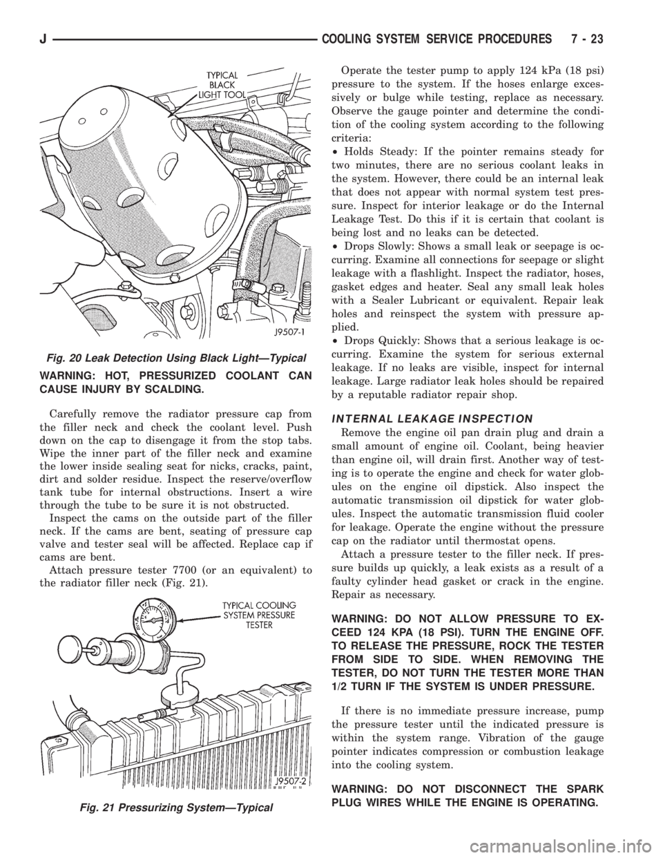
Attach pressure tester 7700 (or an equivalent) to
the radiator filler neck (Fig. 21).Operate the tester pump to apply 124 kPa (18 psi)
pressure to the system. If the hoses enlarge exces-
sively or bulge while testing, replace as necessary.
Observe the gauge pointer and determine the condi-
tion of the cooling system according to the following
criteria:
²Holds Steady: If the pointer remains steady for
two minutes, there are no serious coolant leaks in
the system. However, there could be an internal leak
that does not appear with normal system test pres-
sure. Inspect for interior leakage or do the Internal
Leakage Test. Do this if it is certain that coolant is
being lost and no leaks can be detected.
²Drops Slowly: Shows a small leak or seepage is oc-
curring. Examine all connections for seepage or slight
leakage with a flashlight. Inspect the radiator, hoses,
gasket edges and heater. Seal any small leak holes
with a Sealer Lubricant or equivalent. Repair leak
holes and reinspect the system with pressure ap-
plied.
²Drops Quickly: Shows that a serious leakage is oc-
curring. Examine the system for serious external
leakage. If no leaks are visible, inspect for internal
leakage. Large radiator leak holes should be repaired
by a reputable radiator repair shop.
INTERNAL LEAKAGE INSPECTION
Remove the engine oil pan drain plug and drain a
small amount of engine oil. Coolant, being heavier
than engine oil, will drain first. Another way of test-
ing is to operate the engine and check for water glob-
ules on the engine oil dipstick. Also inspect the
automatic transmission oil dipstick for water glob-
ules. Inspect the automatic transmission fluid cooler
for leakage. Operate the engine without the pressure
cap on the radiator until thermostat opens.
Attach a pressure tester to the filler neck. If pres-
sure builds up quickly, a leak exists as a result of a
faulty cylinder head gasket or crack in the engine.
Repair as necessary.
WARNING: DO NOT ALLOW PRESSURE TO EX-
CEED 124 KPA (18 PSI). TURN THE ENGINE OFF.
TO RELEASE THE PRESSURE, ROCK THE TESTER
FROM SIDE TO SIDE. WHEN REMOVING THE
TESTER, DO NOT TURN THE TESTER MORE THAN
1/2 TURN IF THE SYSTEM IS UNDER PRESSURE.
If there is no immediate pressure increase, pump
the pressure tester until the indicated pressure is
within the system range. Vibration of the gauge
pointer indicates compression or combustion leakage
into the cooling system.
WARNING: DO NOT DISCONNECT THE SPARK
PLUG WIRES WHILE THE ENGINE IS OPERATING.
Fig. 20 Leak Detection Using Black LightÐTypical
Fig. 21 Pressurizing SystemÐTypical
JCOOLING SYSTEM SERVICE PROCEDURES 7 - 23
Page 348 of 2158
motion. Never pull directly on the cable. Internal
damage to cable will result.
(2) Prior to removing the spark plug, spray com-
pressed air around the spark plug hole and the area
around the spark plug. This will help prevent foreign
material from entering the combustion chamber.
(3) Remove the spark plug using a quality socket
with a rubber or foam insert.
(4) Inspect the spark plug condition. Refer to
Spark Plugs in the Diagnostics/Service Procedures
section of this group.
PLUG CLEANING
The plugs may be cleaned using commercially
available spark plug cleaning equipment. After clean-
ing, file the center electrode flat with a small point
file or jewelers file before adjusting gap.
CAUTION: Never use a motorized wire wheel brush
to clean the spark plugs. Metallic deposits will re-
main on the spark plug insulator and will cause
plug misfire.
PLUG GAP ADJUSTMENT
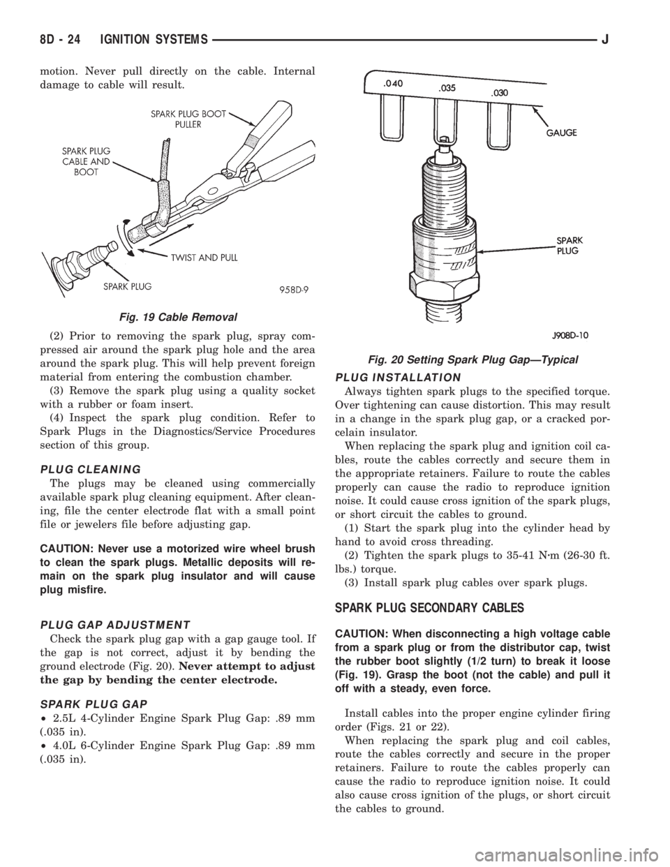
Check the spark plug gap with a gap gauge tool. If
the gap is not correct, adjust it by bending the
ground electrode (Fig. 20).Never attempt to adjust
the gap by bending the center electrode.
SPARK PLUG GAP
²2.5L 4-Cylinder Engine Spark Plug Gap: .89 mm
(.035 in).
²4.0L 6-Cylinder Engine Spark Plug Gap: .89 mm
(.035 in).
PLUG INSTALLATION
Always tighten spark plugs to the specified torque.
Over tightening can cause distortion. This may result
in a change in the spark plug gap, or a cracked por-
celain insulator.
When replacing the spark plug and ignition coil ca-
bles, route the cables correctly and secure them in
the appropriate retainers. Failure to route the cables
properly can cause the radio to reproduce ignition
noise. It could cause cross ignition of the spark plugs,
or short circuit the cables to ground.
(1) Start the spark plug into the cylinder head by
hand to avoid cross threading.
(2) Tighten the spark plugs to 35-41 Nzm (26-30 ft.
lbs.) torque.
(3) Install spark plug cables over spark plugs.
SPARK PLUG SECONDARY CABLES
CAUTION: When disconnecting a high voltage cable
from a spark plug or from the distributor cap, twist
the rubber boot slightly (1/2 turn) to break it loose
(Fig. 19). Grasp the boot (not the cable) and pull it
off with a steady, even force.
Install cables into the proper engine cylinder firing
order (Figs. 21 or 22).
When replacing the spark plug and coil cables,
route the cables correctly and secure in the proper
retainers. Failure to route the cables properly can
cause the radio to reproduce ignition noise. It could
also cause cross ignition of the plugs, or short circuit
the cables to ground.
Fig. 19 Cable Removal
Fig. 20 Setting Spark Plug GapÐTypical
8D - 24 IGNITION SYSTEMSJ
Page 383 of 2158
DIAGNOSIS
GAUGES
If an individual gauge is inoperative, see the diag-
nostic procedure under the heading for that gauge. If
more than one gauge in the main cluster or gauge
package cluster is inoperative, perform the following:
(1) Check fuse 9 in the fuseblock module. If OK, go
to next step. If not OK, replace fuse.
(2) Check for battery voltage at fuse 9 with igni-
tion switch in ON position. If OK, go to next step. If
not OK, repair open in circuit from ignition switch
and/or refer to Group 8D - Ignition Systems for test-
ing of ignition switch.
(3) Turn ignition switch to OFF. Disconnect battery
negative cable. Remove the affected instrument clus-
ter bezel and cluster assembly. Disconnect the cluster
connector.
(4) Connect battery negative cable. Turn ignition
switch to ON. If problem is in main cluster, check for
battery voltage at cavity 3 and cavity 19 of main
cluster connector. If problem is in gauge package
cluster, check for battery voltage at cavity 2 and cav-
ity 12 of gauge package cluster connector. If OK, go
to next step. If not OK, repair open in circuit from
fuse 9 as required.
(5) Turn ignition switch to OFF. Disconnect battery
negative cable. Probe cavities 14 and 20 of main clus-
ter connector, or cavities 1 and 13 of gauge package
cluster connector. Check for continuity to a good
ground. There should be continuity. If OK, replace
the cluster printed circuit. If not OK, repair open in
circuit as required.
COOLANT TEMPERATURE GAUGE
The diagnosis found here addresses an inoperative
gauge condition. If the problem being diagnosed is re-
lated to gauge accuracy, be certain to confirm that
problem is with gauge and not with cooling system
performance. Actual engine coolant temperature
should be checked with a test gauge or thermometer
and compared to gauge readings before you proceed
with gauge diagnosis. Refer to Group 7 - Cooling Sys-
tem for more information.
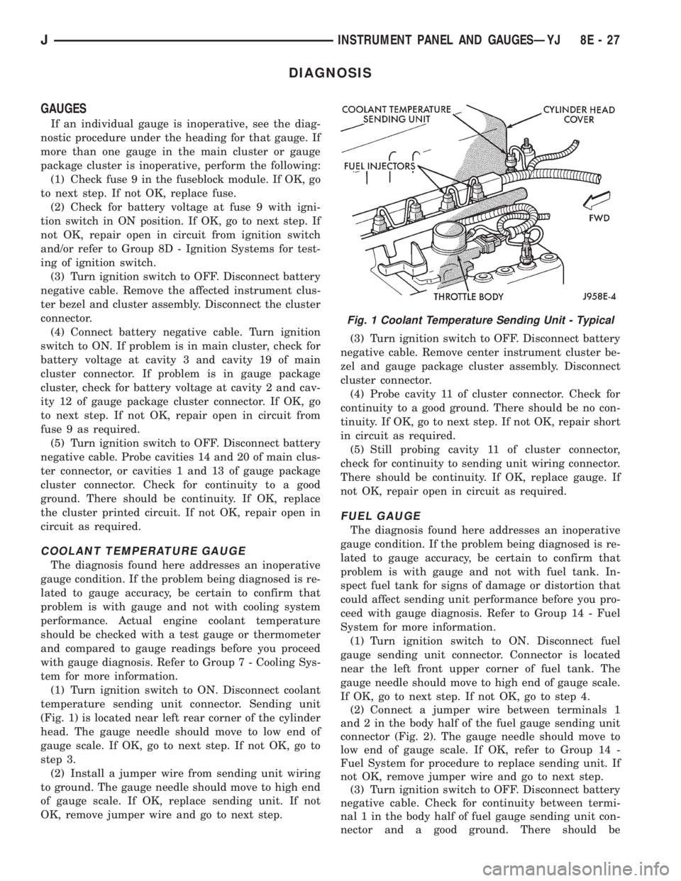
(1) Turn ignition switch to ON. Disconnect coolant
temperature sending unit connector. Sending unit
(Fig. 1) is located near left rear corner of the cylinder
head. The gauge needle should move to low end of
gauge scale. If OK, go to next step. If not OK, go to
step 3.
(2) Install a jumper wire from sending unit wiring
to ground. The gauge needle should move to high end
of gauge scale. If OK, replace sending unit. If not
OK, remove jumper wire and go to next step.(3) Turn ignition switch to OFF. Disconnect battery
negative cable. Remove center instrument cluster be-
zel and gauge package cluster assembly. Disconnect
cluster connector.
(4) Probe cavity 11 of cluster connector. Check for
continuity to a good ground. There should be no con-
tinuity. If OK, go to next step. If not OK, repair short
in circuit as required.
(5) Still probing cavity 11 of cluster connector,
check for continuity to sending unit wiring connector.
There should be continuity. If OK, replace gauge. If
not OK, repair open in circuit as required.
FUEL GAUGE
The diagnosis found here addresses an inoperative
gauge condition. If the problem being diagnosed is re-
lated to gauge accuracy, be certain to confirm that
problem is with gauge and not with fuel tank. In-
spect fuel tank for signs of damage or distortion that
could affect sending unit performance before you pro-
ceed with gauge diagnosis. Refer to Group 14 - Fuel
System for more information.
(1) Turn ignition switch to ON. Disconnect fuel
gauge sending unit connector. Connector is located
near the left front upper corner of fuel tank. The
gauge needle should move to high end of gauge scale.
If OK, go to next step. If not OK, go to step 4.
(2) Connect a jumper wire between terminals 1
and 2 in the body half of the fuel gauge sending unit
connector (Fig. 2). The gauge needle should move to
low end of gauge scale. If OK, refer to Group 14 -
Fuel System for procedure to replace sending unit. If
not OK, remove jumper wire and go to next step.
(3) Turn ignition switch to OFF. Disconnect battery
negative cable. Check for continuity between termi-
nal 1 in the body half of fuel gauge sending unit con-
nector and a good ground. There should be
Fig. 1 Coolant Temperature Sending Unit - Typical
JINSTRUMENT PANEL AND GAUGESÐYJ 8E - 27
Page 427 of 2158
TURN SIGNAL AND HAZARD WARNING SYSTEMS
CONTENTS
page page
DIAGNOSIS............................. 3
GENERAL INFORMATION.................. 1SERVICE PROCEDURES................... 5
GENERAL INFORMATION
Following are general descriptions of the major
components in the XJ (Cherokee)/YJ (Wrangler)
model turn signal and hazard warning systems. Refer
to Group 8W - Wiring Diagrams for complete circuit
descriptions and diagrams.
TURN SIGNAL SYSTEM
With the ignition switch in the ON or ACCESSORY
position and the turn signal switch lever (YJ) or
multi-function switch control lever (XJ) moved up
(right turn) or down (left turn), the turn signal sys-
tem is activated.
When the turn signal system is activated, the se-
lected (right or left) turn signal indicator lamp, front
park/turn signal lamp and rear tail/stop/turn signal
lamp bulb filaments will flash. With the headlamp
switch in the OFF position, the turn and front side
marker lamps flash in unison. With the headlamp
switch in the ON position, the turn and front side
marker lamps flash alternately.
HAZARD WARNING SYSTEM
The hazard warning is activated by a switch button
located below the ignition lock cylinder (YJ) or on the
top of the steering column (XJ) between the steering
wheel and the instrument panel. The hazard warning
flasher (YJ) or combination flasher (XJ) receives bat-
tery feed at all times, and the system is functional
regardless of ignition switch position. The hazard
warning switch button is identified with a double
triangle. On YJ models, push the switch button in to
activate the hazard warning system and pull the
button out to turn system off. On XJ models, push in
on the switch button to latch the switch and activate
the hazard warning system, and push in on the
switch button again to unlatch the switch and turn
the system off.
When the hazard warning system is activated, all
(right and left) turn signal indicator, front park/turn
signal lamp and rear tail/stop/turn signal lamp bulb
filaments will flash.
TURN SIGNAL FLASHER (YJ ONLY)
The turn signal flasher is located in the fuseblock
module. It contains one fixed contact point and one
contact point attached to a flexible bimetal arm. The
contact points are normally closed. When a turn sig-
nal is activated, current flows through the flasher. As
current flows through the bimetal arm it heats and
flexes to pull the contact points open, stopping cur-
rent flow. As the bimetal arm cools it straightens,
until the contact points close and the cycle repeats.
The standard flasher is designed to handle the cur-
rent flow requirements of the factory installed light-
ing. If supplemental lighting is added to the turn
signal circuits such as when towing a trailer with
lights, the current flow through the flasher increases.
This causes the flash rate to increase. It is recom-
mended that the standard flasher be replaced with a
heavy-duty (hazard warning) flasher when supple-
mental lighting is added.
However, when a turn signal bulb fails with a stan-
dard flasher, the remaining bulbs in that circuit will
light, but not flash. This will give the driver an indi-
cation to check the turn signal bulbs. Because a
heavy-duty flasher has different internal circuitry, a
failed bulb will not prevent the remaining bulbs in
the circuit from flashing. Therefore, it is recom-
mended that an occasional visual inspection of exte-
rior turn signal lamp operation be performed when a
heavy-duty flasher is installed.
HAZARD WARNING FLASHER (YJ ONLY)
The hazard warning flasher is located in the fuse-
block module. The hazard warning flasher contains
two normally open contact points mounted to two
flexible arms. A bimetal strip is attached between the
two arms. When the hazard warning is activated,
current flows through the flasher. As the current
flows through the bimetal strip it heats and pulls the
flexible arms together until the contact points close,
JTURN SIGNAL AND HAZARD WARNING SYSTEMS 8J - 1
Page 531 of 2158
CHIME/BUZZER WARNING SYSTEMS
CONTENTS
page page
DIAGNOSIS............................. 2
GENERAL INFORMATION.................. 1SERVICE PROCEDURES................... 4
GENERAL INFORMATION
This group covers the buzzer warning system,
which is standard equipment on XJ (Cherokee)/YJ
(Wrangler) models. The system provides an audible
warning to the driver when it monitors the following
conditions:
²key is in ignition switch with the driver's door
open
²head or park lamps are on with driver's door open
(XJ only)
²driver's seat belt is not buckled with ignition
switch in ON position.
Following are general descriptions of the major
components in the buzzer warning system. Refer to
Group 8W - Wiring Diagrams for complete circuit de-
scriptions and diagrams.
BUZZER MODULE
The buzzer module is located in the fuseblock mod-
ule under the left end of the instrument panel. It re-
ceives battery voltage at all times from (fuse 15 - XJ,
fuse 3 - YJ) the fuseblock module. It also receives a
second battery feed (fuse 17 - XJ, fuse 9 - YJ) when
the ignition switch is in the ON or START position.
Other inputs to the module include the driver's door
jamb switch, the driver's seat belt switch, the ignition
key-in switch, and the headlamp switch (XJ only). The
only output of the module is a timed 4 to 8 second feed
to the seat belt reminder lamp in the message center of
the instrument cluster. The timer function begins after
the ignition switch is turned to the ON position.
The buzzer module can not be repaired. If faulty, it
must be replaced.
DRIVER'S DOOR JAMB SWITCH
The driver's door jamb switch is mounted to the
driver's door hinge pillar. The switch closes a path to
ground for the buzzer module through the key-in
switch or headlamp switch (XJ only) when the driv-
er's door is opened, and opens when the driver's door
is closed. This switch can not be repaired. If faulty, it
must be replaced.
IGNITION KEY-IN SWITCH
XJ MODELS
The key-in switch is integral to the ignition switch,
which is mounted on the right side of the steering col-
umn. It closes a path to ground for the buzzer module
when the ignition key is inserted in the ignition lock cyl-
inder and the driver's door jamb switch is closed (door
open). The switch opens when the key is removed from
the ignition lock cylinder. This switch can not be re-
paired. If faulty, the entire ignition switch must be re-
placed. Refer to Group 8D - Ignition Systems for service
procedures.
YJ MODELS
The key-in switch is mounted within the steering col-
umn in the lock cylinder housing. It closes a path to
ground for the buzzer module when the ignition key is
inserted in the ignition lock cylinder and the driver's
door jamb switch is closed (door open). The switch opens
when the key is removed from the ignition lock cylinder.
This switch is available for service replacement. Refer
to Group 19 - Steering for service procedures.
HEADLAMP SWITCH (XJ ONLY)
The headlamp switch is located in the instrument
panel. It closes a path to ground for the buzzer module
when the park or headlamps are on and the driver's
door jamb switch is closed (door open). The switch opens
the ground path when the park and headlamps are
turned off. The headlamp switch can not be repaired. If
faulty, it must be replaced. Refer to Group 8E - Instru-
ment Panel and Gauges for service procedures.
DRIVER'S SEAT BELT SWITCH
The driver's seat belt switch is integral to the driv-
er's seat belt buckle-half assembly. The switch is nor-
mally closed, providing a ground path to the buzzer
module. When the tip-half of the seat belt is inserted
into the seat belt buckle, the switch opens the buzzer
module ground path. The seat belt switch can not be
repaired. If faulty, the entire driver's seat belt buck-
le-half must be replaced. Refer to Group 23 - Body
Components for service procedures.
JCHIME/BUZZER WARNING SYSTEMS 8U - 1
Page 532 of 2158
DIAGNOSIS
BUZZER MODULE
(1) Check fuses (15 and 17 - XJ, 3 and 9 - YJ) in
the fuseblock module. If fuses are OK, go to next
step. If not OK, replace fuses as required.
(2) Check for battery voltage at fuse (15 - XJ, 3 -
YJ) in fuseblock module. If OK, go to next step. If not
OK, repair feed circuit from power distribution center
as required.
(3) Turn ignition switch to ON position. Check for
battery voltage at fuse (17 - XJ, 9 - YJ) in the fuse-
block module. If OK, go to next step. If not OK, re-
pair feed from ignition switch as required.
(4) Turn ignition switch to OFF position. Replace
buzzer module with a known good unit and test op-
eration. If not OK, remove buzzer module and go to
next step.
(5) Check for battery voltage at cavity for buzzer
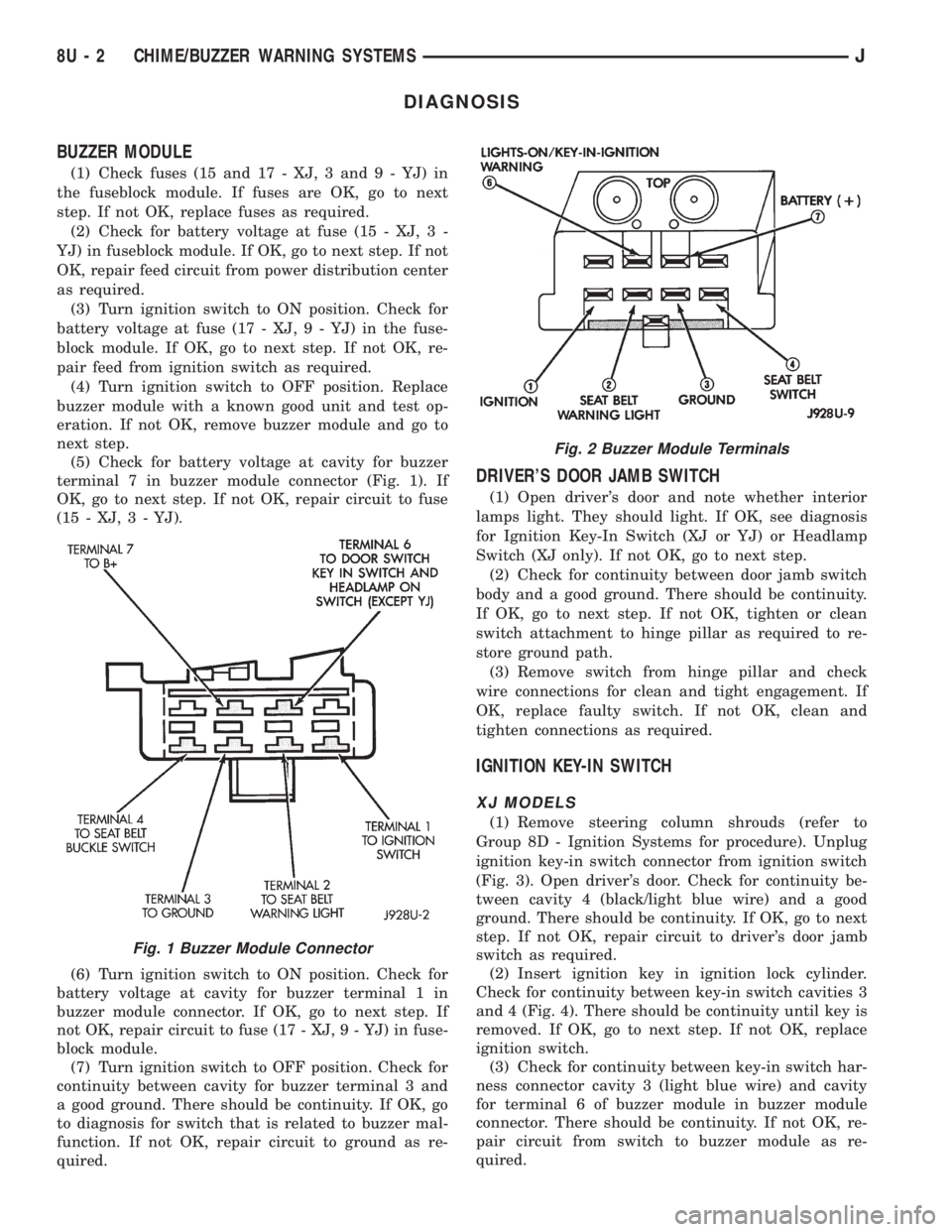
terminal 7 in buzzer module connector (Fig. 1). If
OK, go to next step. If not OK, repair circuit to fuse
(15 - XJ, 3 - YJ).
(6) Turn ignition switch to ON position. Check for
battery voltage at cavity for buzzer terminal 1 in
buzzer module connector. If OK, go to next step. If
not OK, repair circuit to fuse (17 - XJ, 9 - YJ) in fuse-
block module.
(7) Turn ignition switch to OFF position. Check for
continuity between cavity for buzzer terminal 3 and
a good ground. There should be continuity. If OK, go
to diagnosis for switch that is related to buzzer mal-
function. If not OK, repair circuit to ground as re-
quired.
DRIVER'S DOOR JAMB SWITCH
(1) Open driver's door and note whether interior
lamps light. They should light. If OK, see diagnosis
for Ignition Key-In Switch (XJ or YJ) or Headlamp
Switch (XJ only). If not OK, go to next step.
(2) Check for continuity between door jamb switch
body and a good ground. There should be continuity.
If OK, go to next step. If not OK, tighten or clean
switch attachment to hinge pillar as required to re-
store ground path.
(3) Remove switch from hinge pillar and check
wire connections for clean and tight engagement. If
OK, replace faulty switch. If not OK, clean and
tighten connections as required.
IGNITION KEY-IN SWITCH
XJ MODELS
(1) Remove steering column shrouds (refer to
Group 8D - Ignition Systems for procedure). Unplug
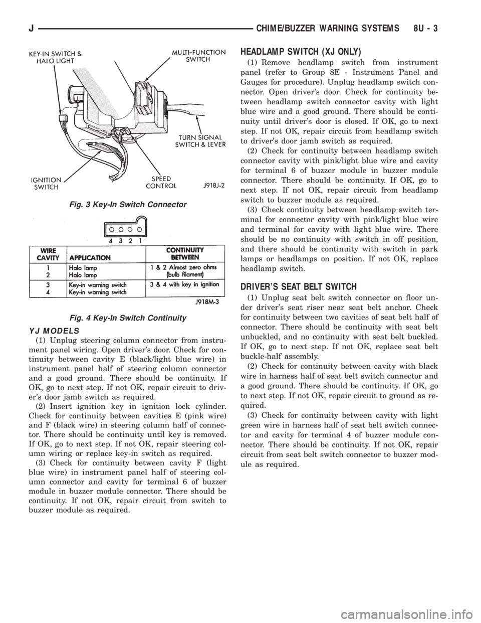
ignition key-in switch connector from ignition switch
(Fig. 3). Open driver's door. Check for continuity be-
tween cavity 4 (black/light blue wire) and a good
ground. There should be continuity. If OK, go to next
step. If not OK, repair circuit to driver's door jamb
switch as required.
(2) Insert ignition key in ignition lock cylinder.
Check for continuity between key-in switch cavities 3
and 4 (Fig. 4). There should be continuity until key is
removed. If OK, go to next step. If not OK, replace
ignition switch.
(3) Check for continuity between key-in switch har-
ness connector cavity 3 (light blue wire) and cavity
for terminal 6 of buzzer module in buzzer module
connector. There should be continuity. If not OK, re-
pair circuit from switch to buzzer module as re-
quired.
Fig. 1 Buzzer Module Connector
Fig. 2 Buzzer Module Terminals
8U - 2 CHIME/BUZZER WARNING SYSTEMSJ
Page 533 of 2158
YJ MODELS
(1) Unplug steering column connector from instru-
ment panel wiring. Open driver's door. Check for con-
tinuity between cavity E (black/light blue wire) in
instrument panel half of steering column connector
and a good ground. There should be continuity. If
OK, go to next step. If not OK, repair circuit to driv-
er's door jamb switch as required.
(2) Insert ignition key in ignition lock cylinder.
Check for continuity between cavities E (pink wire)
and F (black wire) in steering column half of connec-
tor. There should be continuity until key is removed.
If OK, go to next step. If not OK, repair steering col-
umn wiring or replace key-in switch as required.
(3) Check for continuity between cavity F (light
blue wire) in instrument panel half of steering col-
umn connector and cavity for terminal 6 of buzzer
module in buzzer module connector. There should be
continuity. If not OK, repair circuit from switch to
buzzer module as required.
HEADLAMP SWITCH (XJ ONLY)
(1) Remove headlamp switch from instrument
panel (refer to Group 8E - Instrument Panel and
Gauges for procedure). Unplug headlamp switch con-
nector. Open driver's door. Check for continuity be-
tween headlamp switch connector cavity with light
blue wire and a good ground. There should be conti-
nuity until driver's door is closed. If OK, go to next
step. If not OK, repair circuit from headlamp switch
to driver's door jamb switch as required.
(2) Check for continuity between headlamp switch
connector cavity with pink/light blue wire and cavity
for terminal 6 of buzzer module in buzzer module
connector. There should be continuity. If OK, go to
next step. If not OK, repair circuit from headlamp
switch to buzzer module as required.
(3) Check continuity between headlamp switch ter-
minal for connector cavity with pink/light blue wire
and terminal for cavity with light blue wire. There
should be no continuity with switch in off position,
and there should be continuity with switch in park
lamps or headlamps on position. If not OK, replace
headlamp switch.
DRIVER'S SEAT BELT SWITCH
(1) Unplug seat belt switch connector on floor un-
der driver's seat riser near seat belt anchor. Check
for continuity between two cavities of seat belt half of
connector. There should be continuity with seat belt
unbuckled, and no continuity with seat belt buckled.
If OK, go to next step. If not OK, replace seat belt
buckle-half assembly.
(2) Check for continuity between cavity with black
wire in harness half of seat belt switch connector and
a good ground. There should be continuity. If OK, go
to next step. If not OK, repair circuit to ground as re-
quired.
(3) Check for continuity between cavity with light
green wire in harness half of seat belt switch connec-
tor and cavity for terminal 4 of buzzer module con-
nector. There should be continuity. If not OK, repair
circuit from seat belt switch connector to buzzer mod-
ule as required.
Fig. 3 Key-In Switch Connector
Fig. 4 Key-In Switch Continuity
JCHIME/BUZZER WARNING SYSTEMS 8U - 3
Page 785 of 2158
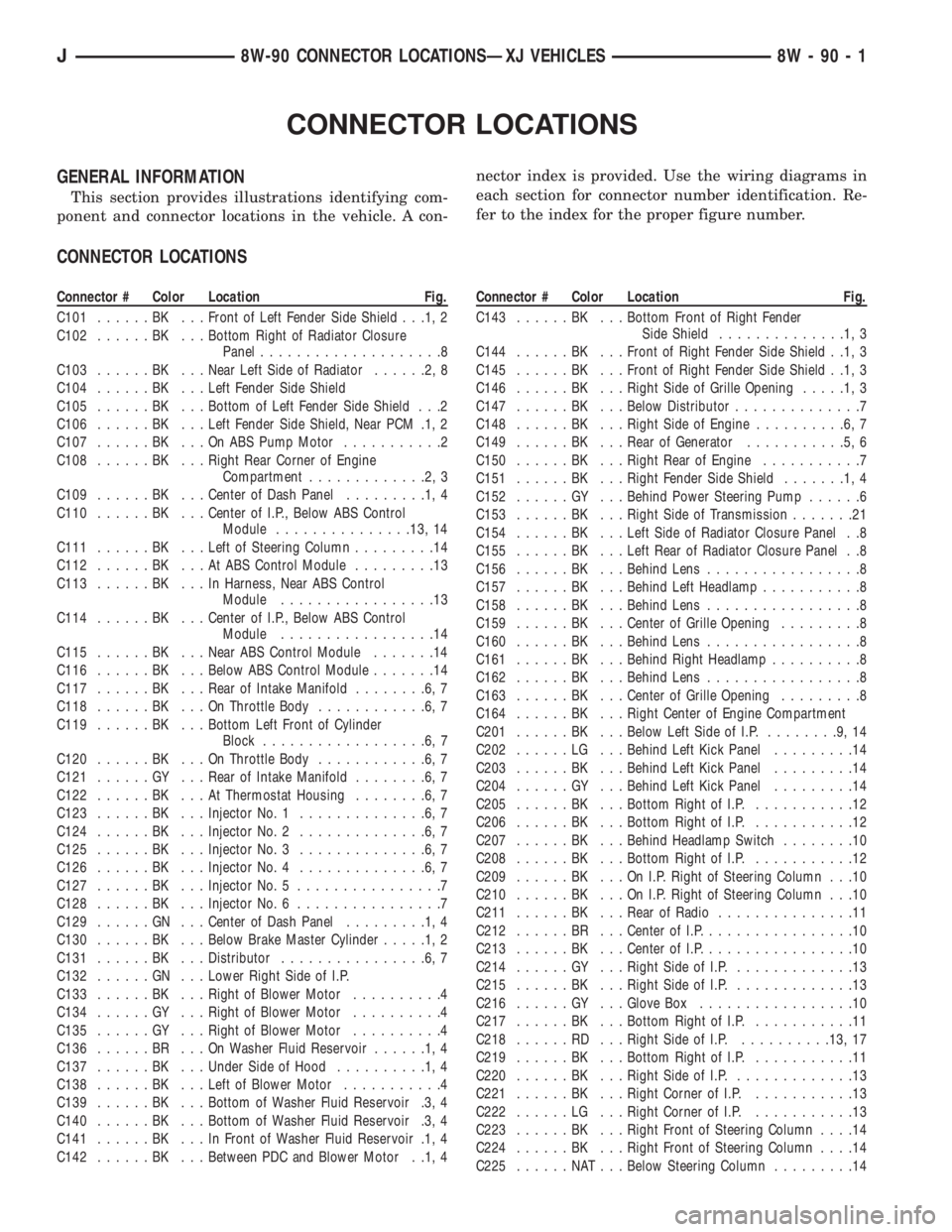
CONNECTOR LOCATIONS
GENERAL INFORMATION
This section provides illustrations identifying com-
ponent and connector locations in the vehicle. A con-nector index is provided. Use the wiring diagrams in
each section for connector number identification. Re-
fer to the index for the proper figure number.
CONNECTOR LOCATIONS
Connector # Color Location Fig.
C101......BK ...Front of Left Fender Side Shield . . .1, 2
C102......BK ...Bottom Right of Radiator Closure
Panel....................8
C103......BK ...Near Left Side of Radiator......2,8
C104......BK ...Left Fender Side Shield
C105......BK ...Bottom of Left Fender Side Shield . . .2
C106......BK ...Left Fender Side Shield, Near PCM .1, 2
C107......BK ...OnABSPump Motor...........2
C108......BK ...Right Rear Corner of Engine
Compartment.............2,3
C109......BK ...Center of Dash Panel.........1,4
C110......BK ...Center of I.P., Below ABS Control
Module...............13, 14
C111......BK ...Left of Steering Column.........14
C112......BK ...AtABSControl Module.........13
C113......BK ...InHarness, Near ABS Control
Module.................13
C114......BK ...Center of I.P., Below ABS Control
Module.................14
C115......BK ...Near ABS Control Module.......14
C116......BK ...Below ABS Control Module.......14
C117......BK ...Rear of Intake Manifold........6,7
C118......BK ...OnThrottle Body............6,7
C119......BK ...Bottom Left Front of Cylinder
Block..................6,7
C120......BK ...OnThrottle Body............6,7
C121......GY ...Rear of Intake Manifold........6,7
C122......BK ...AtThermostat Housing........6,7
C123......BK ...Injector No. 1..............6,7
C124......BK ...Injector No. 2..............6,7
C125......BK ...Injector No. 3..............6,7
C126......BK ...Injector No. 4..............6,7
C127......BK ...Injector No. 5................7
C128......BK ...Injector No. 6................7
C129......GN ...Center of Dash Panel.........1,4
C130......BK ...Below Brake Master Cylinder.....1,2
C131......BK ...Distributor................6,7
C132......GN ...Lower Right Side of I.P.
C133......BK ...Right of Blower Motor..........4
C134......GY ...Right of Blower Motor..........4
C135......GY ...Right of Blower Motor..........4
C136......BR ...OnWasher Fluid Reservoir......1,4
C137......BK ...Under Side of Hood..........1,4
C138......BK ...Left of Blower Motor...........4
C139......BK ...Bottom of Washer Fluid Reservoir .3, 4
C140......BK ...Bottom of Washer Fluid Reservoir .3, 4
C141......BK ...InFront of Washer Fluid Reservoir .1, 4
C142......BK ...Between PDC and Blower Motor . .1, 4Connector # Color Location Fig.
C143......BK ...Bottom Front of Right Fender
Side Shield..............1,3
C144......BK ...Front of Right Fender Side Shield . .1, 3
C145......BK ...Front of Right Fender Side Shield . .1, 3
C146......BK ...Right Side of Grille Opening.....1,3
C147......BK ...Below Distributor..............7
C148......BK ...Right Side of Engine..........6,7
C149......BK ...Rear of Generator...........5,6
C150......BK ...Right Rear of Engine...........7
C151......BK ...Right Fender Side Shield.......1,4
C152......GY ...Behind Power Steering Pump......6
C153......BK ...Right Side of Transmission.......21
C154......BK ...Left Side of Radiator Closure Panel . .8
C155......BK ...Left Rear of Radiator Closure Panel . .8
C156......BK ...Behind Lens.................8
C157......BK ...Behind Left Headlamp...........8
C158......BK ...Behind Lens.................8
C159......BK ...Center of Grille Opening.........8
C160......BK ...Behind Lens.................8
C161......BK ...Behind Right Headlamp..........8
C162......BK ...Behind Lens.................8
C163......BK ...Center of Grille Opening.........8
C164......BK ...Right Center of Engine Compartment
C201......BK ...Below Left Side of I.P.........9,14
C202......LG ...Behind Left Kick Panel.........14
C203......BK ...Behind Left Kick Panel.........14
C204......GY ...Behind Left Kick Panel.........14
C205......BK ...Bottom Right of I.P............12
C206......BK ...Bottom Right of I.P............12
C207......BK ...Behind Headlamp Switch........10
C208......BK ...Bottom Right of I.P............12
C209......BK ...OnI.P.Right of Steering Column . . .10
C210......BK ...OnI.P.Right of Steering Column . . .10
C211......BK ...Rear of Radio...............11
C212......BR ...Center of I.P.................10
C213......BK ...Center of I.P.................10
C214......GY ...Right Side of I.P..............13
C215......BK ...Right Side of I.P..............13
C216......GY ...Glove Box.................10
C217......BK ...Bottom Right of I.P............11
C218......RD ...Right Side of I.P...........13, 17
C219......BK ...Bottom Right of I.P............11
C220......BK ...Right Side of I.P..............13
C221......BK ...Right Corner of I.P............13
C222......LG ...Right Corner of I.P............13
C223......BK ...Right Front of Steering Column....14
C224......BK ...Right Front of Steering Column....14
C225......NAT...Below Steering Column.........14
J8W-90 CONNECTOR LOCATIONSÐXJ VEHICLES 8W - 90 - 1
Page 1067 of 2158
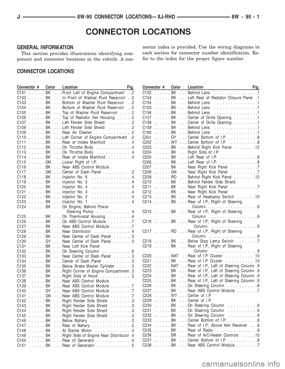
CONNECTOR LOCATIONS
GENERAL INFORMATION
This section provides illustrations identifying com-
ponent and connector locations in the vehicle. A con-nector index is provided. Use the wiring diagrams in
each section for connector number identification. Re-
fer to the index for the proper figure number.
CONNECTOR LOCATIONS
Connector # Color Location Fig.
C101......BK ...Front Left of Engine Compartment . .2
C102......BK ...InFront of Washer Fluid Reservoir . .2
C103......BK ...Bottom of Washer Fluid Reservoir . .2
C104......BK ...Bottom of Washer Fluid Reservoir . .2
C105......BK ...TopofWasher Fluid Reservoir.....2
C106......BK ...TopofRadiator Fan Housing......2
C107......BK ...Left Fender Side Shield.........2
C108......BK ...Left Fender Side Shield.........2
C109......BK ...Near Air Cleaner..............2
C110......BK ...Left Corner of Engine Compartment .2
C111......BK ...Rear of Intake Manifold.........4
C112......BK ...OnThrottle Body.............4
C113......BK ...OnThrottle Body.............4
C114......BK ...Rear of Intake Manifold.........4
C115......GN ...Lower Right of I.P.
C116......BK ...Near ABS Control Module
C117......GN ...Center of Dash Panel...........2
C118......BK ...Injector No. 6...............4
C119......BK ...Injector No. 5...............4
C120......BK ...Injector No. 4...............4
C121......BK ...Injector No. 3...............4
C122......BK ...Injector No. 2...............4
C123......BK ...Injector No. 1...............4
C124......BK ...OnEngine, Behind Power
Steering Pump.............4
C125......BK ...OnThermostat Housing.........4
C126......BK ...OnABSControl Module.........7
C127......BK ...Near ABS Control Module........7
C128......BK ...Near Distributor..............4
C129......BK ...Near Center of Dash Panel.......3
C130......GY ...Near Center of Dash Panel.......3
C131......BK ...Near Left Kick Panel
C132......BK ...OnSteering Column...........6
C133......BK ...Near Center of Dash Panel.......3
C134......BK ...Center of Dash Panel...........3
C135......BK ...Below Brake Master Cylinder......3
C136......BK ...Right Corner of Engine Compartment .3
C137......BK ...Right Side of Hood............3
C138......BK ...Near ABS Control Module
C139......BK ...Near ABS Control Module........7
C140......GY ...Near ABS Control Module........7
C141......GN ...Near ABS Control Module........7
C142......BK ...Right Fender Side Shield........3
C143......BK ...Right Fender Side Shield........3
C144......BK ...Right Fender Side Shield........3
C145......BK ...Right Fender Side Shield........3
C146......BK ...Below Battery................3
C147......BK ...Rear of Battery...............5
C148......BK ...AtStarter Motor..............4
C149......BK ...Right Side of Engine Near Distributor .4
C150......BK ...Rear of Generator.............4
C151......BK ...Rear of Generator.............5Connector # Color Location Fig.
C152......BK ...Behind Lens................1
C153......BK ...Left Rear of Radiator Closure Panel .1
C154......BK ...Behind Lens................1
C155......BK ...Behind Lens................1
C156......BK ...Behind Lens................1
C157......BK ...Center of Grille Opening.........1
C158......BK ...Center of Grille Opening.........1
C159......BK ...Behind Lens................1
C160......BK ...Behind Lens................1
C201......GY ...Center Bottom of I.P............8
C202......WT ...Center Bottom of I.P............8
C203......BK ...Behind Right Kick Panel........12
C204......BK ...Right Side of I.P.
C205......BK ...Left Rear of I.P...............8
C206......BK ...Left Rear of I.P...............8
C207......BK ...Near Right Kick Panel..........7
C208......GN ...Near Right Kick Panel..........7
C209......RD ...Behind Right Kick Panel........12
C210......BK ...Behind Fender Side Shield
C211......BK ...Near Right Kick Panel..........7
C212......BK ...Near Right Kick Panel
C213......BK ...Rear of Headlamp Switch.......10
C214......BK ...Rear of I.P., Right of Steering
Column..................9
C215......BK ...Rear of I.P., Right of Steering
Column..................9
C216......BK ...Rear of I.P., Right of Steering
Column.................9
C217......RD ...Rear of I.P., Right of Steering
Column..................9
C218......BK ...Below Stop Lamp Switch........7
C219......BK ...Rear of I.P., Right of Steering
Column.................9
C220......NAT ..Rear of I.P. Cluster...........10
C221......BK ...Rear of I.P. Cluster...........10
C222......NAT ..Rear of I.P., Left of Steering Column .9
C223......BK ...Rear of I.P., Left of Steering Column .9
C224......BK ...Rear of I.P., Left of Steering Column .9
C225......BK ...Rear of I.P., Left of Steering Column .9
C226......BK ...OnSteering Column...........6
C227......BK ...Near ABS Control Module........7
C228......WT ...Center of I.P.
C229......BK ...Center of I.P.
C230......BK ...OnSteering Column...........6
C231......BK ...OnSteering Column...........6
C232......BK ...OnSteering Column...........6
C233......BK ...Center Bottom of I.P............8
C234......BK ...Rear of I.P., Above Ash Receiver . . .8
C235......BK ...Rear of Radio...............9
C236......BR ...Rear of A/C-Heater Controls.....10
C237......BK ...Center Bottom of I.P............8
C238......BK ...Near ABS Control Module........7
J8W-90 CONNECTOR LOCATIONSÐXJ-RHD 8W - 90 - 1