check engine light JEEP YJ 1995 Service And User Guide
[x] Cancel search | Manufacturer: JEEP, Model Year: 1995, Model line: YJ, Model: JEEP YJ 1995Pages: 2158, PDF Size: 81.9 MB
Page 175 of 2158
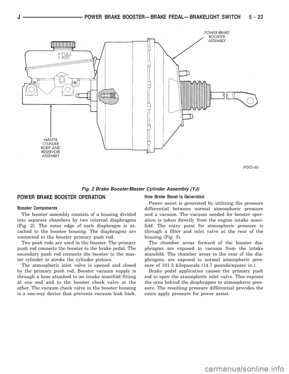
POWER BRAKE BOOSTER OPERATION
Booster Components
The booster assembly consists of a housing divided
into separate chambers by two internal diaphragms
(Fig. 2). The outer edge of each diaphragm is at-
tached to the booster housing. The diaphragms are
connected to the booster primary push rod.
Two push rods are used in the booster. The primary
push rod connects the booster to the brake pedal. The
secondary push rod connects the booster to the mas-
ter cylinder to stroke the cylinder pistons.
The atmospheric inlet valve is opened and closed
by the primary push rod. Booster vacuum supply is
through a hose attached to an intake manifold fitting
at one end and to the booster check valve at the
other. The vacuum check valve in the booster housing
is a one-way device that prevents vacuum leak back.How Brake Boost Is Generated
Power assist is generated by utilizing the pressure
differential between normal atmospheric pressure
and a vacuum. The vacuum needed for booster oper-
ation is taken directly from the engine intake mani-
fold. The entry point for atmospheric pressure is
through a filter and inlet valve at the rear of the
housing (Fig. 3).
The chamber areas forward of the booster dia-
phragms are exposed to vacuum from the intake
manifold. The chamber areas to the rear of the dia-
phragms, are exposed to normal atmospheric pres-
sure of 101.3 kilopascals (14.7 pounds/square in.).
Brake pedal application causes the primary push
rod to open the atmospheric inlet valve. This exposes
the area behind the diaphragms to atmospheric pres-
sure. The resulting pressure differential provides the
extra apply pressure for power assist.
Fig. 2 Brake Booster/Master Cylinder Assembly (YJ)
JPOWER BRAKE BOOSTERÐBRAKE PEDALÐBRAKELIGHT SWITCH 5 - 23
Page 181 of 2158
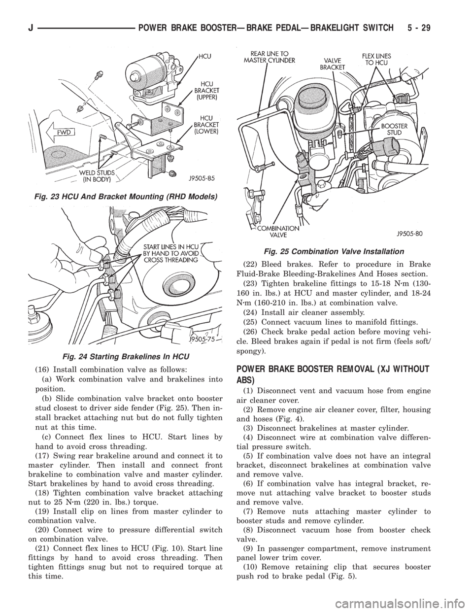
(16) Install combination valve as follows:
(a) Work combination valve and brakelines into
position.
(b) Slide combination valve bracket onto booster
stud closest to driver side fender (Fig. 25). Then in-
stall bracket attaching nut but do not fully tighten
nut at this time.
(c) Connect flex lines to HCU. Start lines by
hand to avoid cross threading.
(17) Swing rear brakeline around and connect it to
master cylinder. Then install and connect front
brakeline to combination valve and master cylinder.
Start brakelines by hand to avoid cross threading.
(18) Tighten combination valve bracket attaching
nut to 25 Nzm (220 in. lbs.) torque.
(19) Install clip on lines from master cylinder to
combination valve.
(20) Connect wire to pressure differential switch
on combination valve.
(21) Connect flex lines to HCU (Fig. 10). Start line
fittings by hand to avoid cross threading. Then
tighten fittings snug but not to required torque at
this time.(22) Bleed brakes. Refer to procedure in Brake
Fluid-Brake Bleeding-Brakelines And Hoses section.
(23) Tighten brakeline fittings to 15-18 Nzm (130-
160 in. lbs.) at HCU and master cylinder, and 18-24
Nzm (160-210 in. lbs.) at combination valve.
(24) Install air cleaner assembly.
(25) Connect vacuum lines to manifold fittings.
(26) Check brake pedal action before moving vehi-
cle. Bleed brakes again if pedal is not firm (feels soft/
spongy).POWER BRAKE BOOSTER REMOVAL (XJ WITHOUT
ABS)
(1) Disconnect vent and vacuum hose from engine
air cleaner cover.
(2) Remove engine air cleaner cover, filter, housing
and hoses (Fig. 4).
(3) Disconnect brakelines at master cylinder.
(4) Disconnect wire at combination valve differen-
tial pressure switch.
(5) If combination valve does not have an integral
bracket, disconnect brakelines at combination valve
and remove valve.
(6) If combination valve has integral bracket, re-
move nut attaching valve bracket to booster studs
and remove valve.
(7) Remove nuts attaching master cylinder to
booster studs and remove cylinder.
(8) Disconnect vacuum hose from booster check
valve.
(9) In passenger compartment, remove instrument
panel lower trim cover.
(10) Remove retaining clip that secures booster
push rod to brake pedal (Fig. 5).
Fig. 23 HCU And Bracket Mounting (RHD Models)
Fig. 24 Starting Brakelines In HCU
Fig. 25 Combination Valve Installation
JPOWER BRAKE BOOSTERÐBRAKE PEDALÐBRAKELIGHT SWITCH 5 - 29
Page 182 of 2158
(11) Remove nuts attaching booster to passenger
compartment side of dash panel.
(12) In engine compartment, slide booster studs
out of dash panel, tilt booster upward, and remove
booster from engine compartment.
(13) Remove dash seal from booster.
(14) If booster is only being removed for access to
other components, cover booster front opening with
clean shop towel.
POWER BRAKE BOOSTER INSTALLATION (XJ
WITHOUT ABS)
(1) If original booster is being installed, test check
valve with vacuum tool before booster installation.
Replace check valve if it will not hold vacuum.
(2) Install dash seal on booster.
(3) Align and position booster on dash panel (Fig.
17).
(4) In passenger compartment, install nuts that at-
tach booster to dash panel. Tighten nuts just enough
to hold booster in place.
(5) Slide booster push rod onto brake pedal. Then
secure push rod to pedal pin with retaining clip.
(6) Tighten booster attaching nuts to 41 Nzm (30 ft.
lbs.) on XJ and 34 Nzm (25 ft. lbs.) on YJ.
(7) Install instrument panel lower trim cover.
(8) If original master cylinder is being installed,
check condition of seal at rear of master cylinder
(Fig. 18). Clean and reposition seal if dislodged. Re-
place seal if cut, or torn.
(9) Clean cylinder mounting surface of brake
booster. Use shop towel wetted with brake cleaner for
this purpose. Dirt, grease, or similar materials will
prevent proper cylinder seating and could result in
vacuum leak.
(10) Align and install master cylinder on booster
studs. Tighten cylinder attaching nuts to 13-25 Nzm
(115-220 in. lbs.) torque.
(11) Connect vacuum hose to booster check valve.
(12) Connect and secure brakelines to combination
valve and master cylinder. Start all brakeline fittings
by hand to avoid cross threading.
(13) If combination valve has integral bracket, po-
sition bracket on booster studs. Then install and
tighten bracket attaching nuts to 13-25 Nzm (115-220
in. lbs.) torque.
(14) Connect wire to combination valve switch.
(15) Top off master cylinder fluid level.
(16) Bleed brakes. Refer to procedures in section
on brake bleeding.
(17) Install engine air cleaner and hoses.
(18) Verify proper brake operation before moving
vehicle.
POWER BRAKE BOOSTER REMOVAL (YJ)
(1) Disconnect brakelines at master cylinder. Then
loosen lines at combination valve and move lines
away from cylinder.
(2) Remove nuts master cylinder to booster studs.
(3) If combination valve has integral bracket, slide
bracket off studs and move valve aside.
(4) Remove master cylinder. Slide cylinder off
studs and remove it from engine compartment.
(5) Working under instrument panel, remove re-
tainer clip that secures booster push rod to brake
pedal.
(6) Disconnect vacuum hose at booster check valve.
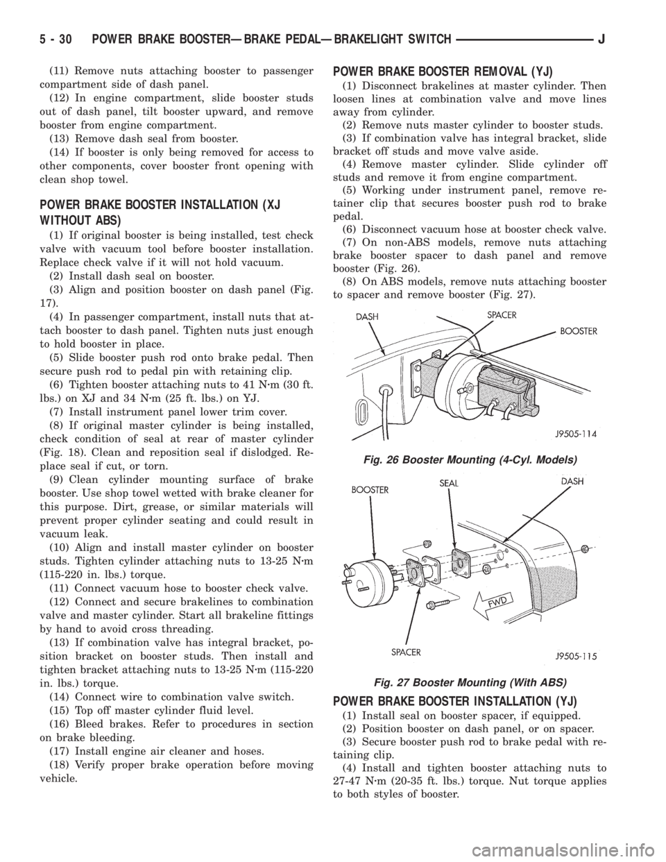
(7) On non-ABS models, remove nuts attaching
brake booster spacer to dash panel and remove
booster (Fig. 26).
(8) On ABS models, remove nuts attaching booster
to spacer and remove booster (Fig. 27).
POWER BRAKE BOOSTER INSTALLATION (YJ)
(1) Install seal on booster spacer, if equipped.
(2) Position booster on dash panel, or on spacer.
(3) Secure booster push rod to brake pedal with re-
taining clip.
(4) Install and tighten booster attaching nuts to
27-47 Nzm (20-35 ft. lbs.) torque. Nut torque applies
to both styles of booster.
Fig. 26 Booster Mounting (4-Cyl. Models)
Fig. 27 Booster Mounting (With ABS)
5 - 30 POWER BRAKE BOOSTERÐBRAKE PEDALÐBRAKELIGHT SWITCHJ
Page 233 of 2158
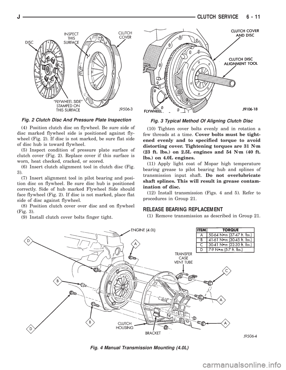
(4) Position clutch disc on flywheel. Be sure side of
disc marked flywheel side is positioned against fly-
wheel (Fig. 2). If disc is not marked, be sure flat side
of disc hub is toward flywheel.
(5) Inspect condition of pressure plate surface of
clutch cover (Fig. 2). Replace cover if this surface is
worn, heat checked, cracked, or scored.
(6) Insert clutch alignment tool in clutch disc (Fig.
3).
(7) Insert alignment tool in pilot bearing and posi-
tion disc on flywheel. Be sure disc hub is positioned
correctly. Side of hub marked Flywheel Side should
face flywheel (Fig. 2). If disc is not marked, place flat
side of disc against flywheel.
(8) Position clutch cover over disc and on flywheel
(Fig. 3).
(9) Install clutch cover bolts finger tight.(10) Tighten cover bolts evenly and in rotation a
few threads at a time.Cover bolts must be tight-
ened evenly and to specified torque to avoid
distorting cover. Tightening torques are 31 Nzm
(23 ft. lbs.) on 2.5L engines and 54 Nzm (40 ft.
lbs.) on 4.0L engines.
(11) Apply light coat of Mopar high temperature
bearing grease to pilot bearing hub and splines of
transmission input shaft.Do not overlubricate
shaft splines. This will result in grease contam-
ination of disc.
(12) Install transmission (Figs. 4 and 5). Refer to
procedures in Group 21.
RELEASE BEARING REPLACEMENT
(1) Remove transmission as described in Group 21.
Fig. 2 Clutch Disc And Pressure Plate InspectionFig. 3 Typical Method Of Aligning Clutch Disc
Fig. 4 Manual Transmission Mounting (4.0L)
JCLUTCH SERVICE 6 - 11
Page 244 of 2158
EXAMPLES:
²If the lamp (Figs. 5 or 6) flashes 1 time, pauses
and flashes 2 more times, a flashing Diagnostic Trou-
ble Code (DTC) number 12 is indicated. If this code is
observed, it is indicating that the battery has been
disconnected within the last 50 key-on cycles. It
could also indicate that battery voltage has been dis-
connected to the PCM. In either case, other DTC's
may have been erased.
²If the lamp flashes 1 time, pauses and flashes 7
more times, a flashing Diagnostic Trouble Code
(DTC) number 17 is indicated.
²If the lamp flashes 3 times, pauses and flashes 5
more times, a flashing Diagnostic Trouble Code
(DTC) number 35 is indicated.
After any stored DTC information has been ob-
served, the display will end with a flashing DTC
number 55. This will indicate the end of all stored in-
formation.
ERASING TROUBLE CODES
After the problem has been repaired, the DRB scan
tool must be used to erase a DTC. Refer to the ap-
propriate Powertrain Diagnostic Procedures service
manual for operation of the DRB scan tool.
DRB SCAN TOOL
For operation of the DRB scan tool, refer to the ap-
propriate Powertrain Diagnostic Procedures service
manual.
PRELIMINARY CHECKS
ENGINE COOLING SYSTEM OVERHEATING
Establish what driving conditions caused the com-
plaint. Abnormal loads on the cooling system such as
the following may be the cause.
1. PROLONGED IDLE, VERY HIGH AMBIENT
TEMPERATURE, SLIGHT TAIL WIND AT IDLE,
SLOW TRAFFIC, TRAFFIC JAMS, HIGH
SPEED, OR STEEP GRADES:
Driving techniques that avoid overheating are:
²Idle with A/C off when temperature gauge is at
end of normal range.
²Increasing engine speed for more air flow is recom-
mended.
2. TRAILER TOWING:
Consult Trailer Towing section of owners manual.
Do not exceed limits.
3. AIR CONDITIONING; ADD-ON OR AFTER
MARKET:
A maximum cooling package should have been or-
dered with vehicle if add-on or after market A/C is
installed. If not, maximum cooling system compo-
nents should be installed for model involved per
manufacturer's specifications.
4. RECENT SERVICE OR ACCIDENT REPAIR:
Determine if any recent service has been performed
on vehicle that may effect cooling system. This may
be:
²Engine adjustments (incorrect timing)
²Slipping engine accessory drive belt(s)
²Brakes (possibly dragging)
²Changed parts (incorrect water pump rotating in
wrong direction)
²Reconditioned radiator or cooling system refilling
(possibly under-filled or air trapped in system).
If investigation reveals none of the previous
items as a cause for an engine overheating com-
plaint, refer to following Cooling System Diag-
nosis charts.
These charts are to be used as a quick-reference
only. Refer to the group text for information.
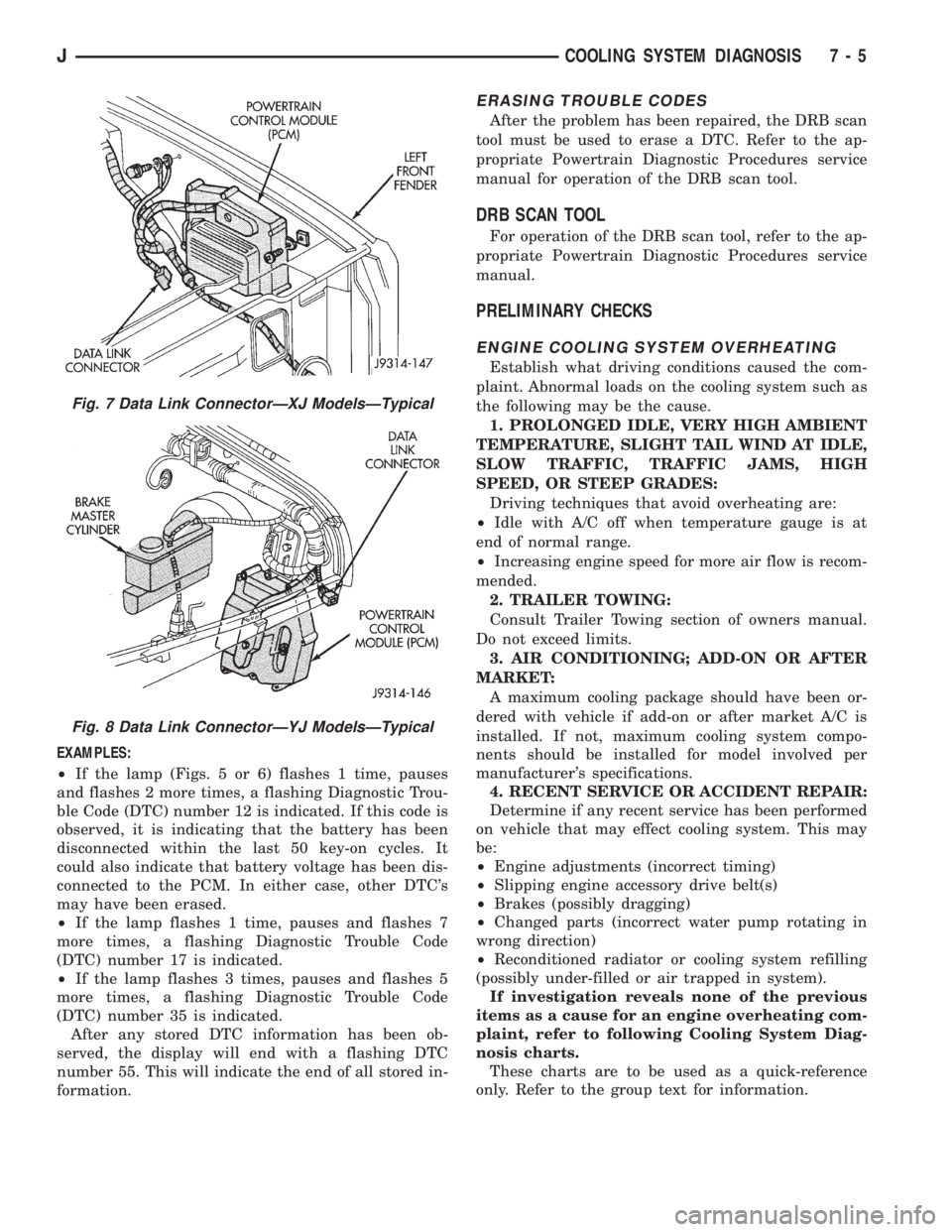
Fig. 7 Data Link ConnectorÐXJ ModelsÐTypical
Fig. 8 Data Link ConnectorÐYJ ModelsÐTypical
JCOOLING SYSTEM DIAGNOSIS 7 - 5
Page 259 of 2158
COOLANT
GENERAL INFORMATION
The cooling system is designed around the coolant.
Coolant flows through the engine water jackets ab-
sorbing heat produced during engine operation. The
coolant carries heat to the radiator and heater core.
Here it is transferred to the ambient air passing
through the radiator and heater core fins. The cool-
ant also removes heat from the automatic transmis-
sion fluid in vehicles equipped with an automatic
transmission.
COOLANT PERFORMANCE
The required ethylene-glycol (antifreeze) and water
mixture depends upon climate and vehicle operating
conditions. The coolant performance of various mix-
tures follows:
Pure Water-Water can absorb more heat than a
mixture of water and ethylene-glycol. This is for pur-
pose of heat transfer only. Water also freezes at a
higher temperature and allows corrosion.
100 percent Ethylene-Glycol-The corrosion in-
hibiting additives in ethylene-glycol need the pres-
ence of water to dissolve. Without water, additives
form deposits in system. These act as insulation
causing temperature to rise to as high as 149ÉC
(300ÉF). This temperature is hot enough to melt plas-
tic and soften solder. The increased temperature can
result in engine detonation. In addition, 100 percent
ethylene-glycol freezes at -22ÉC (-8ÉF).
50/50 Ethylene-Glycol and Water-Is the recom-
mended mixture, it provides protection against freez-
ing to -37ÉC (-35ÉF). The antifreeze concentration
must alwaysbe a minimum of 44 percent, year-
round in all climates. If percentage is lower, engine
parts may be eroded by cavitation. Maximum protec-
tion against freezing is provided with a 68 percent
antifreeze concentration, which prevents freezing
down to -67.7ÉC (-90ÉF). A higher percentage will
freeze at a warmer temperature. Also, a higher per-
centage of antifreeze can cause the engine to over-
heat because specific heat of antifreeze is lower than
that of water.
CAUTION: Richer antifreeze mixtures cannot be
measured with normal field equipment and can
cause problems associated with 100 percent ethyl-
ene-glycol.
COOLANT SELECTION-ADDITIVES
Coolant should be maintained at the specified level
with a mixture of ethylene glycol-based antifreeze
and low mineral content water. Only use an anti-
freeze containing ALUGARD 340-2 Ÿ.CAUTION: Do not use coolant additives that are
claimed to improve engine cooling.
COOLANT SERVICE
It is recommended that the cooling system be
drained and flushed at 84,000 kilometers (52,500
miles), or 3 years, whichever occurs first. Then every
two years, or 48,000 kilometers (30,000 miles),
whichever occurs first.
COOLANT LEVEL CHECKÐROUTINE
Do not remove radiator cap for routine cool-
ant level inspections. The coolant level can be
checked at coolant reserve/overflow tank.
The coolant reserve/overflow system provides a
quick visual method for determining coolant level
without removing radiator pressure cap. With engine
idling and at normal operating temperature, observe
coolant level in reserve/overflow tank. The coolant
level should be between ADD and FULL marks.
ADDING ADDITIONAL COOLANTÐROUTINE
Do not remove radiator cap to add coolant to
system.When adding coolant to maintain correct
level, do so at coolant reserve/overflow tank. Use a
50/50 mixture of ethylene-glycol antifreeze containing
Alugard 340-2 Ÿ and low mineral content water. Re-
move radiator cap only for testing or when refilling
system after service. Removing cap unnecessarily can
cause loss of coolant and allow air to enter system,
which produces corrosion.
COOLANT LEVEL CHECK-SERVICE
The cooling system is closed and designed to main-
tain coolant level to top of radiator.
WARNING: DO NOT OPEN RADIATOR DRAINCOCK
WITH ENGINE RUNNING OR WHILE ENGINE IS HOT
AND COOLING SYSTEM IS UNDER PRESSURE.
When vehicle servicing requires a coolant level
check in radiator, drain several ounces of coolant
from radiator drain cock. Do this while observing
coolant reserve/overflow system tank. The coolant
level in reserve/overflow tank should drop slightly. If
not, inspect for a leak between radiator and coolant
reserve/overflow system connection. Remove radiator
cap. The coolant level should be to top of radiator. If
not and if coolant level in reserve/overflow tank is at
ADD mark, check for:
²An air leak in coolant reserve/overflow tank or its
hose
²An air leak in radiator filler neck
²Leak in pressure cap seal to radiator filler neck
LOW COOLANT LEVEL-AERATION
If the coolant level in radiator drops below top of
radiator core tubes, air will enter cooling system.
7 - 20 COOLING SYSTEM SERVICE PROCEDURESJ
Page 261 of 2158
group. Fill radiator to top and install radiator cap.
Add sufficient coolant to reserve/overflow tank to
raise level to FULL mark.
(3) With heater control unit in the HEAT position,
operate engine with radiator cap in place.
(4) After engine has reached normal operating
temperature, shut engine off and allow it to cool.
(5) Add coolant to reserve/overflow tank as neces-
sary.Only add coolant when the engine is cold.
Coolant level in a warm engine will be higher
due to thermal expansion.
COOLING SYSTEM CLEANING/REVERSE FLUSHING
CAUTION: The cooling system normally operates at
97-to-124 kPa (14-to-18 psi) pressure. Exceeding
this pressure may damage the radiator or hoses.
CLEANING
Drain cooling system and refill with water. Run en-
gine with radiator cap installed until upper radiator
hose is hot. Stop engine and drain water from sys-
tem. If water is dirty, fill system with water, run en-
gine and drain system. Repeat until water drains
clean.
REVERSE FLUSHING
Reverse flushing of the cooling system is the forc-
ing of water through the cooling system. This is done
using air pressure in the opposite direction of normal
coolant flow. It is usually only necessary with very
dirty systems with evidence of partial plugging.
REVERSE FLUSHING RADIATOR
Disconnect the radiator hoses from the radiator fit-
tings. Attach a section of radiator hose to the radia-
tor bottom outlet fitting and insert the flushing gun.
Connect a water supply hose and air supply hose to
the flushing gun.
CAUTION: The cooling system normally operates at
97-to-124 kPa (14-to-18 psi) pressure. Exceeding
this pressure may damage the radiator or hoses.
Allow the radiator to fill with water. When radiator
is filled, apply air in short blasts allowing radiator to
refill between blasts. Continue this reverse flushing
until clean water flows out through rear of radiator
cooling tube passages. For more information, refer to
operating instructions supplied with flushing equip-
ment. Have radiator cleaned more extensively by a
radiator repair shop.
REVERSE FLUSHING ENGINE
Drain the cooling system. Remove the thermostat
housing and thermostat. Install the thermostat hous-
ing. Disconnect the radiator upper hose from the ra-
diator and attach the flushing gun to the hose.Disconnect the radiator lower hose from the water
pump. Attach a lead away hose to the water pump
inlet fitting.
CAUTION: On XJ models, be sure that the heater
control valve is closed (heat off). This is done to
prevent coolant flow with scale and other deposits
from entering the heater core.
Connect the water supply hose and air supply hose
to the flushing gun. Allow the engine to fill with wa-
ter. When the engine is filled, apply air in short
blasts, allowing the system to fill between air blasts.
Continue until clean water flows through the lead
away hose. For more information, refer to operating
instructions supplied with flushing equipment.
Remove the lead away hose, flushing gun, water
supply hose and air supply hose. Remove the thermo-
stat housing and install thermostat. Install the ther-
mostat housing with a replacement gasket. Refer to
Thermostat Replacement. Connect the radiator
hoses. Refill the cooling system with the correct an-
tifreeze/water mixture.
CHEMICAL CLEANING
In some instances, use a radiator cleaner (Mopar
Radiator Kleen or equivalent) before flushing. This
will soften scale and other deposits and aid the flush-
ing operation.
CAUTION: Be sure instructions on the container are
followed.
TESTING COOLING SYSTEM FOR LEAKS
ULTRAVIOLET LIGHT METHOD
All Jeep models have a leak detection additive
added to the cooling system before they leave the fac-
tory. The additive is highly visible under ultraviolet
light (black light). If the factory original coolant has
been drained, pour one ounce of additive into the
cooling system. The additive is available through the
part's department. Place the heater control unit in
HEAT position. Start and operate the engine until
the radiator upper hose is warm to the touch. Aim
the commercially available black light tool at the
components to be checked. If leaks are present, the
black light will cause the additive to glow a bright
green color.
The black light can be used along with a pressure
tester to determine if any external leaks exist (Fig.
20).
PRESSURE TESTER METHOD
The engine should be at the normal operating tem-
perature. Recheck the system cold if the cause of
coolant loss is not located during warm engine exam-
ination.
7 - 22 COOLING SYSTEM SERVICE PROCEDURESJ
Page 262 of 2158
WARNING: HOT, PRESSURIZED COOLANT CAN
CAUSE INJURY BY SCALDING.
Carefully remove the radiator pressure cap from
the filler neck and check the coolant level. Push
down on the cap to disengage it from the stop tabs.
Wipe the inner part of the filler neck and examine
the lower inside sealing seat for nicks, cracks, paint,
dirt and solder residue. Inspect the reserve/overflow
tank tube for internal obstructions. Insert a wire
through the tube to be sure it is not obstructed.
Inspect the cams on the outside part of the filler
neck. If the cams are bent, seating of pressure cap
valve and tester seal will be affected. Replace cap if
cams are bent.
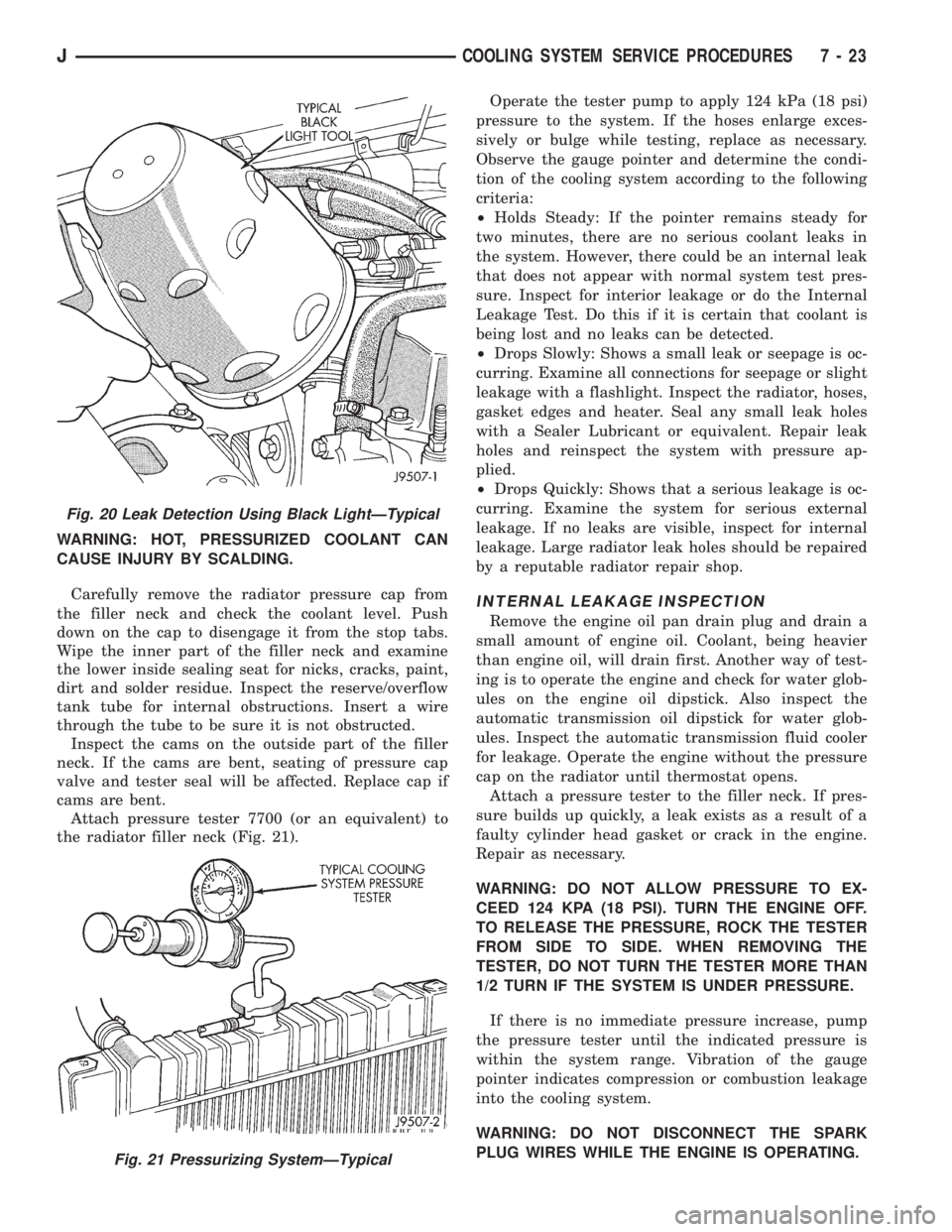
Attach pressure tester 7700 (or an equivalent) to
the radiator filler neck (Fig. 21).Operate the tester pump to apply 124 kPa (18 psi)
pressure to the system. If the hoses enlarge exces-
sively or bulge while testing, replace as necessary.
Observe the gauge pointer and determine the condi-
tion of the cooling system according to the following
criteria:
²Holds Steady: If the pointer remains steady for
two minutes, there are no serious coolant leaks in
the system. However, there could be an internal leak
that does not appear with normal system test pres-
sure. Inspect for interior leakage or do the Internal
Leakage Test. Do this if it is certain that coolant is
being lost and no leaks can be detected.
²Drops Slowly: Shows a small leak or seepage is oc-
curring. Examine all connections for seepage or slight
leakage with a flashlight. Inspect the radiator, hoses,
gasket edges and heater. Seal any small leak holes
with a Sealer Lubricant or equivalent. Repair leak
holes and reinspect the system with pressure ap-
plied.
²Drops Quickly: Shows that a serious leakage is oc-
curring. Examine the system for serious external
leakage. If no leaks are visible, inspect for internal
leakage. Large radiator leak holes should be repaired
by a reputable radiator repair shop.
INTERNAL LEAKAGE INSPECTION
Remove the engine oil pan drain plug and drain a
small amount of engine oil. Coolant, being heavier
than engine oil, will drain first. Another way of test-
ing is to operate the engine and check for water glob-
ules on the engine oil dipstick. Also inspect the
automatic transmission oil dipstick for water glob-
ules. Inspect the automatic transmission fluid cooler
for leakage. Operate the engine without the pressure
cap on the radiator until thermostat opens.
Attach a pressure tester to the filler neck. If pres-
sure builds up quickly, a leak exists as a result of a
faulty cylinder head gasket or crack in the engine.
Repair as necessary.
WARNING: DO NOT ALLOW PRESSURE TO EX-
CEED 124 KPA (18 PSI). TURN THE ENGINE OFF.
TO RELEASE THE PRESSURE, ROCK THE TESTER
FROM SIDE TO SIDE. WHEN REMOVING THE
TESTER, DO NOT TURN THE TESTER MORE THAN
1/2 TURN IF THE SYSTEM IS UNDER PRESSURE.
If there is no immediate pressure increase, pump
the pressure tester until the indicated pressure is
within the system range. Vibration of the gauge
pointer indicates compression or combustion leakage
into the cooling system.
WARNING: DO NOT DISCONNECT THE SPARK
PLUG WIRES WHILE THE ENGINE IS OPERATING.
Fig. 20 Leak Detection Using Black LightÐTypical
Fig. 21 Pressurizing SystemÐTypical
JCOOLING SYSTEM SERVICE PROCEDURES 7 - 23
Page 274 of 2158
(5) Be sure that the air conditioner (if equipped) is
turned off.
WARNING: USE EXTREME CAUTION WHEN THE
ENGINE IS OPERATING. DO NOT STAND IN A DI-
RECT LINE WITH THE FAN. DO NOT PUT YOUR
HANDS NEAR THE PULLEYS, BELTS OR FAN. DO
NOT WEAR LOOSE CLOTHING.
(6) Start the engine and operate at 2400 rpm.
Within ten minutes the air temperature (indicated on
the dial thermometer) should be up to 88É C (190É F).
Fan driveengagementshould have started to occur
at between 74É to 82É C (165É to 180É F). Engage-
ment is distinguishable by a definiteincreasein fan
flow noise (roaring). The timing light also will indi-
cate an increase in the speed of the fan.
(7) When the air temperature reaches 88É C (190É
F), remove the plastic sheet. Fan drivedisengage-
mentshould have started to occur at between 57É to
79É C (135É to 175É F). A definitedecreaseof fan
flow noise (roaring) should be noticed. If not, replace
the defective viscous fan drive unit.
VISCOUS FAN DRIVE REMOVAL/INSTALLATION
Refer to the previous section on Cooling System
Fan for removal and installation procedures of the
viscous drive unit.
Viscous Fan Drive Fluid Pump Out Require-
ment:After installing anewviscous fan drive, bring
the engine speed up to approximately 2000 rpm and
hold for approximately two minutes. This will ensure
proper fluid distribution within the drive.
AUXILIARY ELECTRIC COOLING FANÐXJ MODELS
WITH 4.0L 6-CYLINDER ENGINE
OPERATION
XJ models equipped with a 4.0L 6-cylinder engine
may also have an auxiliary electrical cooling fan.
This is with models that have air conditioning and/or
heavy duty cooling. The fan is controlled by the cool-
ing fan relay, which is located in the power distribu-
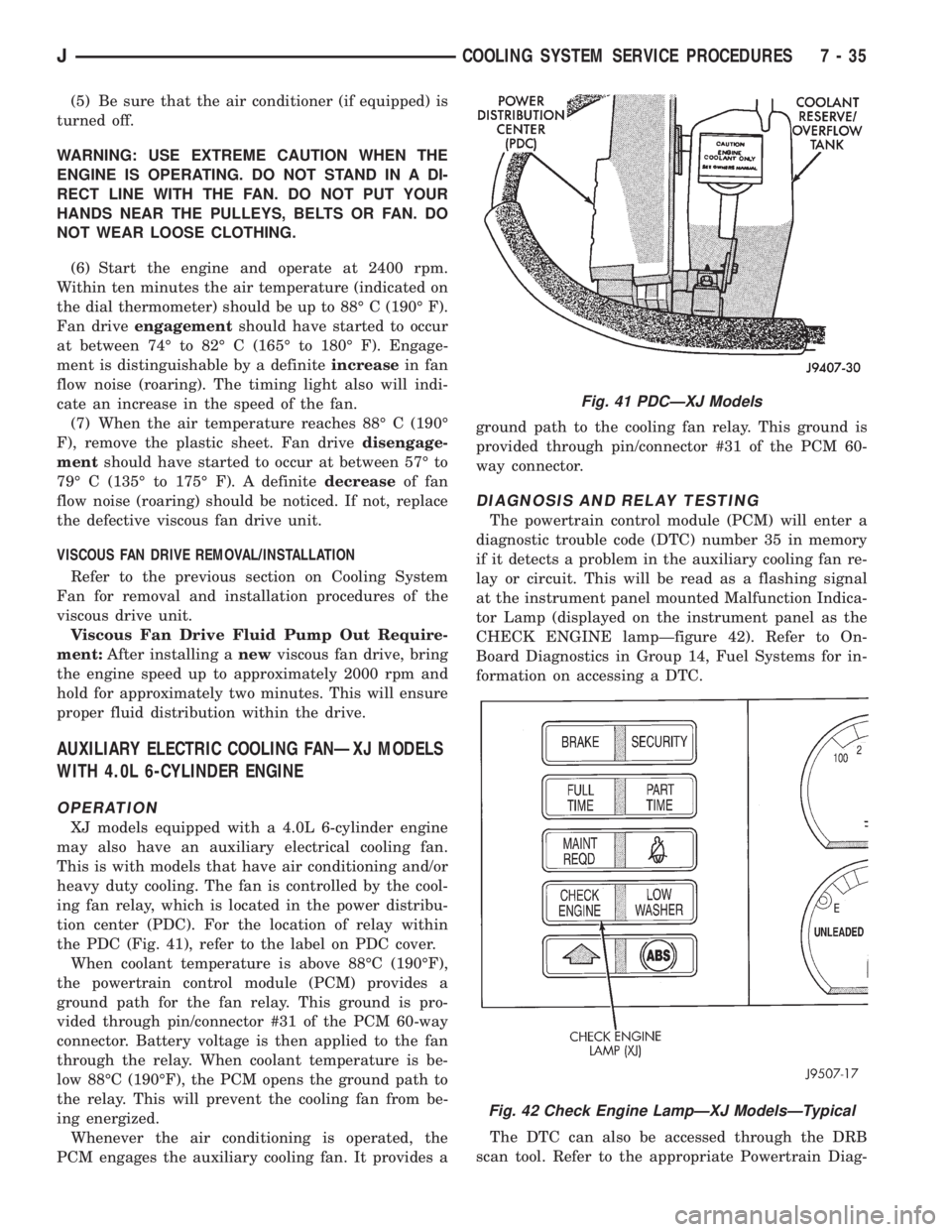
tion center (PDC). For the location of relay within
the PDC (Fig. 41), refer to the label on PDC cover.
When coolant temperature is above 88ÉC (190ÉF),
the powertrain control module (PCM) provides a
ground path for the fan relay. This ground is pro-
vided through pin/connector #31 of the PCM 60-way
connector. Battery voltage is then applied to the fan
through the relay. When coolant temperature is be-
low 88ÉC (190ÉF), the PCM opens the ground path to
the relay. This will prevent the cooling fan from be-
ing energized.
Whenever the air conditioning is operated, the
PCM engages the auxiliary cooling fan. It provides aground path to the cooling fan relay. This ground is
provided through pin/connector #31 of the PCM 60-
way connector.
DIAGNOSIS AND RELAY TESTING
The powertrain control module (PCM) will enter a
diagnostic trouble code (DTC) number 35 in memory
if it detects a problem in the auxiliary cooling fan re-
lay or circuit. This will be read as a flashing signal
at the instrument panel mounted Malfunction Indica-
tor Lamp (displayed on the instrument panel as the
CHECK ENGINE lampÐfigure 42). Refer to On-
Board Diagnostics in Group 14, Fuel Systems for in-
formation on accessing a DTC.
The DTC can also be accessed through the DRB
scan tool. Refer to the appropriate Powertrain Diag-
Fig. 41 PDCÐXJ Models
Fig. 42 Check Engine LampÐXJ ModelsÐTypical
JCOOLING SYSTEM SERVICE PROCEDURES 7 - 35
Page 288 of 2158
charged. However, even with these vents, hydrogen
gas can collect in or around the battery. If hydrogen
gas is exposed to flame or sparks, it can ignite.
If the electrolyte level is low, the battery could arc
internally and explode. If the battery is equipped
with removable cell caps, add distilled water when-
ever the electrolyte level is below the top of the
plates. If the battery cell caps cannot be removed, the
battery must be replaced when the electrolyte level is
low.
WARNING: DO NOT ATTEMPT TO ASSIST BOOST,
CHARGE, OR TEST BATTERY WHEN ELECTRO-
LYTE LEVEL IS BELOW THE TOP OF THE PLATES.
PERSONAL INJURY MAY OCCUR.
BATTERY RATINGS
Currently, there are 2 commonly accepted methods
for rating and comparing battery performance. These
ratings are called Cold Cranking Amperage (CCA),
and Reserve Capacity (RC). Be certain that a replace-
ment battery has CCA and RC ratings that equal or
exceed the original equipment specification for the
vehicle being serviced. See Battery Classifications
and Ratings charts in Specifications at the back of
this group.
COLD CRANKING AMPERAGE
The Cold Cranking Amperage (CCA) rating speci-
fies how much current (in amperes) the battery can
deliver for 30 seconds at -17.7ÉC (0ÉF). Terminal volt-
age must not fall below 7.2 volts during or after the
30 second discharge. The CCA required is generally
higher as engine displacement increases, depending
also upon the starter current draw requirements.
RESERVE CAPACITY
The Reserve Capacity (RC) rating specifies the
time (in minutes) it takes for battery terminal volt-
age to fall below 10.2 volts at a discharge rate of 25
amps. RC is determined with the battery fully-
charged at 26.7ÉC (80ÉF). This rating estimates how
long the battery might last after a charging system
failure, under minimum electrical load.
DIAGNOSIS
The battery must be completely charged and the
top, posts, and terminal clamps should be properly
cleaned before diagnostic procedures are performed.
Refer to Group 8B - Battery/Starter/Generator Ser-
vice for more information.
The condition of a battery is determined by two cri-
teria:
(1)State-Of-ChargeThis can be determined by
viewing the built-in test indicator, by checking spe-
cific gravity of the electrolyte (hydrometer test), or by
checking battery voltage (open circuit voltage test).(2)Cranking CapacityThis can be determined
by performing a battery load test, which measures
the ability of the battery to supply high-amperage
current.
If the battery has a built-in test indicator, use this
test first. If it has no test indicator, but has remov-
able cell caps, perform the hydrometer test first. If
cell caps are not removable, or a hydrometer is not
available, perform the open circuit voltage test first.
The battery must be charged before proceeding
with a load test if:
²the built-in test indicator has a black or dark color
visible
²the temperature corrected specific gravity is less
than 1.235
²the open circuit voltage is less than 12.4 volts.
A battery that will not accept a charge is faulty
and further testing is not required. A battery that is
fully-charged, but does not pass the load test is
faulty and must be replaced.
Completely discharged batteries may take
several hours to accept a charge. See Charging
Completely Discharged Battery.
A battery is fully-charged when:
²all cells are gassing freely during charging
²a green color is visible in the sight glass of the
built-in test indicator
²three corrected specific gravity tests, taken at
1-hour intervals, indicate no increase in specific grav-
ity
²open circuit voltage is 12.4 volts or greater.
ABNORMAL BATTERY DISCHARGING
Any of the following conditions can result in abnor-
mal battery discharging:
(1) Corroded battery posts and terminals.
(2) Loose or worn generator drive belt.
(3) Electrical loads that exceed the output of the
charging system, possibly due to equipment installed
after manufacture or repeated short trip use.
(4) Slow driving speeds (heavy traffic conditions) or
prolonged idling with high-amperage draw systems
in use.
(5) Faulty circuit or component causing excessive
ignition-off draw. See Ignition-Off Draw in this group
for diagnosis.
(6) Faulty charging system.
(7) Faulty or incorrect battery.
BUILT-IN TEST INDICATOR
A test indicator (hydrometer) built into the top of
the battery case, provides visual information for bat-
tery testing (Fig. 1). It is important when using the
test indicator that the battery be level and have a
clean sight glass to see correct indications. Additional
light may be required to view indicator.
JBATTERY/STARTING/CHARGING SYSTEMS DIAGNOSTICS 8A - 3