oil temperature JEEP YJ 1995 Service And User Guide
[x] Cancel search | Manufacturer: JEEP, Model Year: 1995, Model line: YJ, Model: JEEP YJ 1995Pages: 2158, PDF Size: 81.9 MB
Page 325 of 2158

IGNITION SYSTEMS
CONTENTS
page page
COMPONENT IDENTIFICATION/SYSTEM
OPERATION........................... 1
COMPONENT REMOVAL/INSTALLATION...... 17
DIAGNOSTICS/SERVICE PROCEDURES....... 6IGNITION SWITCHÐXJ MODELS........... 26
IGNITION SWITCHÐYJ MODELS........... 29
SPECIFICATIONS........................ 32
COMPONENT IDENTIFICATION/SYSTEM OPERATION
INDEX
page page
Automatic Shutdown (ASD) Relay.............. 1
Camshaft Position Sensor.................... 2
Crankshaft Position Sensor................... 3
Distributors............................... 4
Engine Coolant Temperature Sensor............ 5
General Information........................ 1Ignition Coil.............................. 4
Intake Manifold Air Temperature Sensor.......... 5
Manifold Absolute Pressure (MAP) Sensor........ 5
Oxygen (O2S) Sensor....................... 5
Powertrain Control Module (PCM).............. 5
Throttle Position Sensor..................... 5
GENERAL INFORMATION
Throughout this group, references are made to par-
ticular vehicle models by alphabetical designation
(XJ or YJ) or by the particular vehicle nameplate. A
chart showing a breakdown of alphabetical designa-
tions is included in the Introduction group at the be-
ginning of this manual.
This section of the group, Component Identifica-
tion/System Operation, will discuss ignition system
operation and will identify ignition system compo-
nents.
For diagnostic procedures and adjustments, refer to
the Diagnostics/Service Procedures section of this
group.
For removal and installation of ignition system
components, refer to the Component Removal/Instal-
lation section of this group.
For other useful information, refer to On-Board Di-
agnostics in the General Diagnosis sections of Group
14, Fuel System in this manual.
For operation of the DRB Scan Tool, refer to the
appropriate Powertrain Diagnostic Procedures ser-
vice manual.
An Ignition specifications section is included at the
end of this group. A general Maintenance Schedule
(mileage intervals) for ignition related items can be
found in Group 0, Lubrication and Maintenance. This
schedule can also be found in the Owners Manual.
IGNITION SYSTEMS
A multi-port, fuel injected engine is used on all
models. The ignition system is controlled by the pow-
ertrain control module (PCM) on all engines. The
PCM was formerly referred to as the SBEC or engine
controller.
The ignition system consists of:
²Spark plugs
²Ignition coil
²Secondary ignition cables
²Distributor (contains rotor and camshaft position
sensor)
²Powertrain control module (PCM)
²Crankshaft position sensor
AUTOMATIC SHUTDOWN (ASD) RELAY
The automatic shutdown (ASD) relay is located in
the power distribution center (PDC) near the battery
(Fig. 1 or 2). As one of its functions, it will supply
battery voltage to the ignition coil.
The ground circuit for the ASD relay is controlled
by the powertrain control module (PCM). This is
done through pin/cavity number 51 of the PCM 60-
way connector. The PCM then regulates ASD relay
operation by switching this ground circuit on-and-off.
Also refer to Ignition Coil for additional informa-
tion.
JIGNITION SYSTEMS 8D - 1
Page 329 of 2158
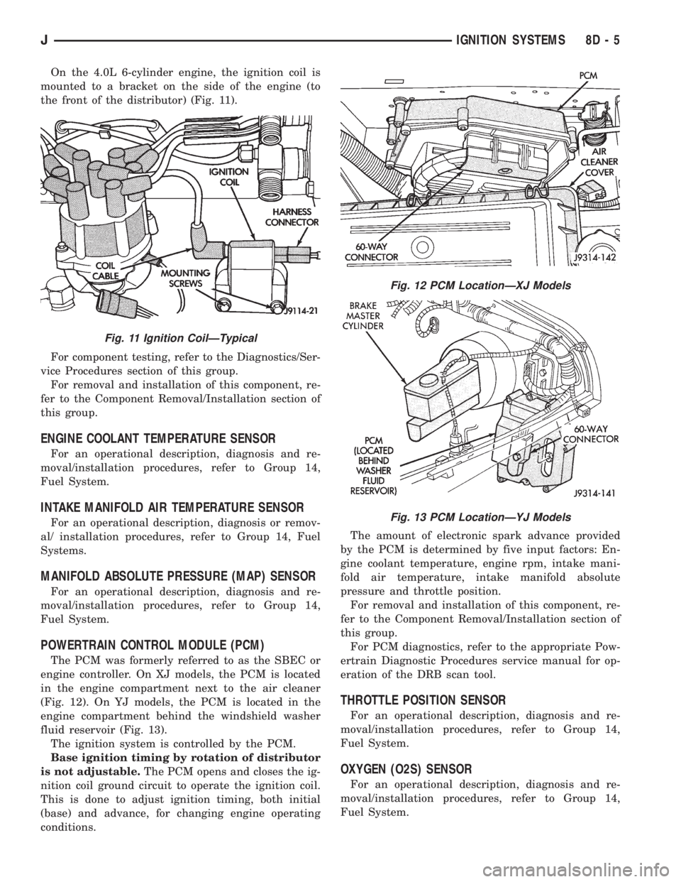
On the 4.0L 6-cylinder engine, the ignition coil is
mounted to a bracket on the side of the engine (to
the front of the distributor) (Fig. 11).
For component testing, refer to the Diagnostics/Ser-
vice Procedures section of this group.
For removal and installation of this component, re-
fer to the Component Removal/Installation section of
this group.
ENGINE COOLANT TEMPERATURE SENSOR
For an operational description, diagnosis and re-
moval/installation procedures, refer to Group 14,
Fuel System.
INTAKE MANIFOLD AIR TEMPERATURE SENSOR
For an operational description, diagnosis or remov-
al/ installation procedures, refer to Group 14, Fuel
Systems.
MANIFOLD ABSOLUTE PRESSURE (MAP) SENSOR
For an operational description, diagnosis and re-
moval/installation procedures, refer to Group 14,
Fuel System.
POWERTRAIN CONTROL MODULE (PCM)
The PCM was formerly referred to as the SBEC or
engine controller. On XJ models, the PCM is located
in the engine compartment next to the air cleaner
(Fig. 12). On YJ models, the PCM is located in the
engine compartment behind the windshield washer
fluid reservoir (Fig. 13).
The ignition system is controlled by the PCM.
Base ignition timing by rotation of distributor
is not adjustable.The PCM opens and closes the ig-
nition coil ground circuit to operate the ignition coil.
This is done to adjust ignition timing, both initial
(base) and advance, for changing engine operating
conditions.The amount of electronic spark advance provided
by the PCM is determined by five input factors: En-
gine coolant temperature, engine rpm, intake mani-
fold air temperature, intake manifold absolute
pressure and throttle position.
For removal and installation of this component, re-
fer to the Component Removal/Installation section of
this group.
For PCM diagnostics, refer to the appropriate Pow-
ertrain Diagnostic Procedures service manual for op-
eration of the DRB scan tool.
THROTTLE POSITION SENSOR
For an operational description, diagnosis and re-
moval/installation procedures, refer to Group 14,
Fuel System.
OXYGEN (O2S) SENSOR
For an operational description, diagnosis and re-
moval/installation procedures, refer to Group 14,
Fuel System.
Fig. 11 Ignition CoilÐTypical
Fig. 12 PCM LocationÐXJ Models
Fig. 13 PCM LocationÐYJ Models
JIGNITION SYSTEMS 8D - 5
Page 330 of 2158

DIAGNOSTICS/SERVICE PROCEDURES
INDEX
page page
Automatic Shutdown (ASD) Relay Test.......... 6
Camshaft Position Sensor Test................ 6
Crankshaft Position Sensor Test............... 7
Distributor Cap............................ 7
Distributor Rotor........................... 8
DRB Scan Tool............................ 8
Engine Coolant Temperature Sensor Test........ 9
General Information........................ 6
Ignition Coil.............................. 9
Ignition Secondary Circuit Diagnosis........... 10Ignition Timing............................ 11
Intake Manifold Air Temperature Sensor Test..... 11
Manifold Absolute Pressure (MAP) Sensor Test . . . 11
On-Board Diagnostics...................... 15
Oxygen (O2S) Sensor Tests................. 15
Powertrain Control Module (PCM)............. 11
Spark Plug Secondary Cables................ 14
Spark Plugs............................. 12
Throttle Position Sensor Test................. 15
GENERAL INFORMATION
This section of the group, Diagnostics/Service Pro-
cedures, will discuss basic ignition system diagnostics
and service adjustments.
For system operation and component identification,
refer to the Component Identification/System Opera-
tion section of this group.
For removal or installation of ignition system com-
ponents, refer to the Component Removal/Installa-
tion section of this group.
For other useful information, refer to the On-Board
Diagnostics section.
For operation of the DRB Scan Tool, refer to the
appropriate Powertrain Diagnostic Procedures ser-
vice manual.
AUTOMATIC SHUTDOWN (ASD) RELAY TEST
To perform a complete test of this relay and its cir-
cuitry, refer to the DRB scan tool. Also refer to the
appropriate Powertrain Diagnostics Procedures man-
ual. To test the relay only, refer to RelaysÐOpera-
tion/Testing in the Group 14, Fuel Systems section.
CAMSHAFT POSITION SENSOR TEST
To perform a complete test of this sensor and its
circuitry, refer to the DRB scan tool. Also refer to the
appropriate Powertrain Diagnostics Procedures man-
ual. To test the sensor only, refer to the following:
The camshaft position sensor is located in the dis-
tributor (Fig. 1).
To perform a complete test of this sensor and its
circuitry, refer to the DRB scan tool. Also refer to the
appropriate Powertrain Diagnostics Procedures man-
ual. To test the sensor only, refer to the following:
For this test, an analog (non-digital) voltme-
ter is needed.Do not remove the distributor connec-
tor from the distributor. Using small paper clips,
insert them into the backside of the distributor wire
harness connector to make contact with the termi-nals. Be sure that the connector is not damaged
when inserting the paper clips. Attach voltmeter
leads to these paper clips.
(1) Connect the positive (+) voltmeter lead into the
sensor output wire. This is at done the distributor
wire harness connector. For wire identification, refer
to Group 8W, Wiring Diagrams.
(2) Connect the negative (-) voltmeter lead into the
ground wire. For wire identification, refer to Group
8W, Wiring Diagrams.
(3) Set the voltmeter to the 15 Volt DC scale.
(4) Remove distributor cap from distributor (two
screws). Rotate (crank) the engine until the distribu-
tor rotor is pointed to approximately the 11 o'clock
position. The movable pulse ring should now be
within the sensor pickup.
(5) Turn ignition key to ON position. The voltmeter
should read approximately 5.0 volts.
(6) If voltage is not present, check the voltmeter
leads for a good connection.
(7) If voltage is still not present, check for voltage
at the supply wire. For wire identification, refer to
Group 8W, Wiring Diagrams.
Fig. 1 Camshaft Position SensorÐTypical
8D - 6 IGNITION SYSTEMSJ
Page 333 of 2158
IGNITION COIL
To perform a complete test of the ignition coil and
its circuitry, refer to the DRB scan tool. Also refer tothe appropriate Powertrain Diagnostics Procedures
manual. To test the coil only, refer to the following:
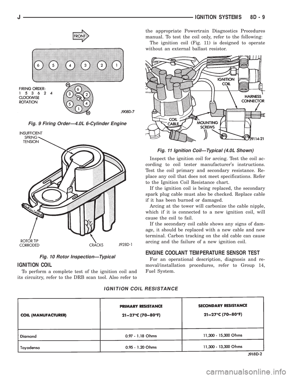
The ignition coil (Fig. 11) is designed to operate
without an external ballast resistor.
Inspect the ignition coil for arcing. Test the coil ac-
cording to coil tester manufacturer's instructions.
Test the coil primary and secondary resistance. Re-
place any coil that does not meet specifications. Refer
to the Ignition Coil Resistance chart.
If the ignition coil is being replaced, the secondary
spark plug cable must also be checked. Replace cable
if it has been burned or damaged.
Arcing at the tower will carbonize the cable nipple,
which if it is connected to a new ignition coil, will
cause the coil to fail.
If the secondary coil cable shows any signs of dam-
age, it should be replaced with a new cable and new
terminal. Carbon tracking on the old cable can cause
arcing and the failure of a new ignition coil.
ENGINE COOLANT TEMPERATURE SENSOR TEST
For an operational description, diagnosis and re-
moval/installation procedures, refer to Group 14,
Fuel System.
IGNITION COIL RESISTANCE
Fig. 9 Firing OrderÐ4.0L 6-Cylinder Engine
Fig. 10 Rotor InspectionÐTypical
Fig. 11 Ignition CoilÐTypical (4.0L Shown)
JIGNITION SYSTEMS 8D - 9
Page 335 of 2158
(4) Crank the engine for 5 seconds while monitor-
ing the voltage at the coil positive terminal:
²If the voltage remains near zero during the entire
period of cranking, refer to On-Board Diagnostics in
Group 14, Fuel Systems. Check the powertrain con-
trol module (PCM) and auto shutdown relay.
²If voltage is at or near battery voltage and drops
to zero after 1-2 seconds of cranking, check the cam-
shaft position sensor-to-PCM circuit. Refer to On-
Board Diagnostics in Group 14, Fuel Systems.
²If voltage remains at or near battery voltage dur-
ing the entire 5 seconds, turn the key off. Remove
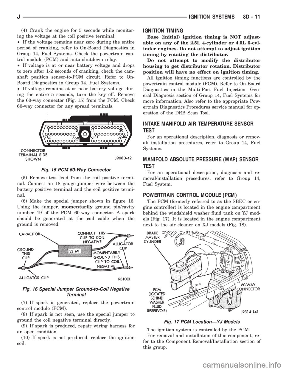
the 60-way connector (Fig. 15) from the PCM. Check
60-way connector for any spread terminals.
(5) Remove test lead from the coil positive termi-
nal. Connect an 18 gauge jumper wire between the
battery positive terminal and the coil positive termi-
nal.
(6) Make the special jumper shown in figure 16.
Using the jumper,momentarilyground pin/cavity
number 19 of the PCM 60-way connector. A spark
should be generated at the coil cable when the
ground is removed.
(7) If spark is generated, replace the powertrain
control module (PCM).
(8) If spark is not seen, use the special jumper to
ground the coil negative terminal directly.
(9) If spark is produced, repair wiring harness for
an open condition.
(10) If spark is not produced, replace the ignition
coil.IGNITION TIMING
Base (initial) ignition timing is NOT adjust-
able on any of the 2.5L 4-cylinder or 4.0L 6-cyl-
inder engines. Do not attempt to adjust ignition
timing by rotating the distributor.
Do not attempt to modify the distributor
housing to get distributor rotation. Distributor
position will have no effect on ignition timing.
All ignition timing functions are controlled by the
powertrain control module (PCM). Refer to On-Board
Diagnostics in the Multi-Port Fuel InjectionÐGen-
eral Diagnosis section of Group 14, Fuel Systems for
more information. Also refer to the appropriate Pow-
ertrain Diagnostics Procedures service manual for op-
eration of the DRB Scan Tool.
INTAKE MANIFOLD AIR TEMPERATURE SENSOR
TEST
For an operational description, diagnosis or remov-
al/ installation procedures, refer to Group 14, Fuel
Systems.
MANIFOLD ABSOLUTE PRESSURE (MAP) SENSOR
TEST
For an operational description, diagnosis and re-
moval/installation procedures, refer to Group 14,
Fuel System.
POWERTRAIN CONTROL MODULE (PCM)
The PCM (formerly referred to as the SBEC or en-
gine controller) is located in the engine compartment
behind the windshield washer fluid tank on YJ mod-
els (Fig. 17). It is located in the engine compartment
next to the air cleaner on XJ models (Fig. 18).
The ignition system is controlled by the PCM.
For removal and installation of this component, re-
fer to the Component Removal/Installation section of
this group.
Fig. 15 PCM 60-Way Connector
Fig. 16 Special Jumper Ground-to-Coil Negative
Terminal
Fig. 17 PCM LocationÐYJ Models
JIGNITION SYSTEMS 8D - 11
Page 337 of 2158
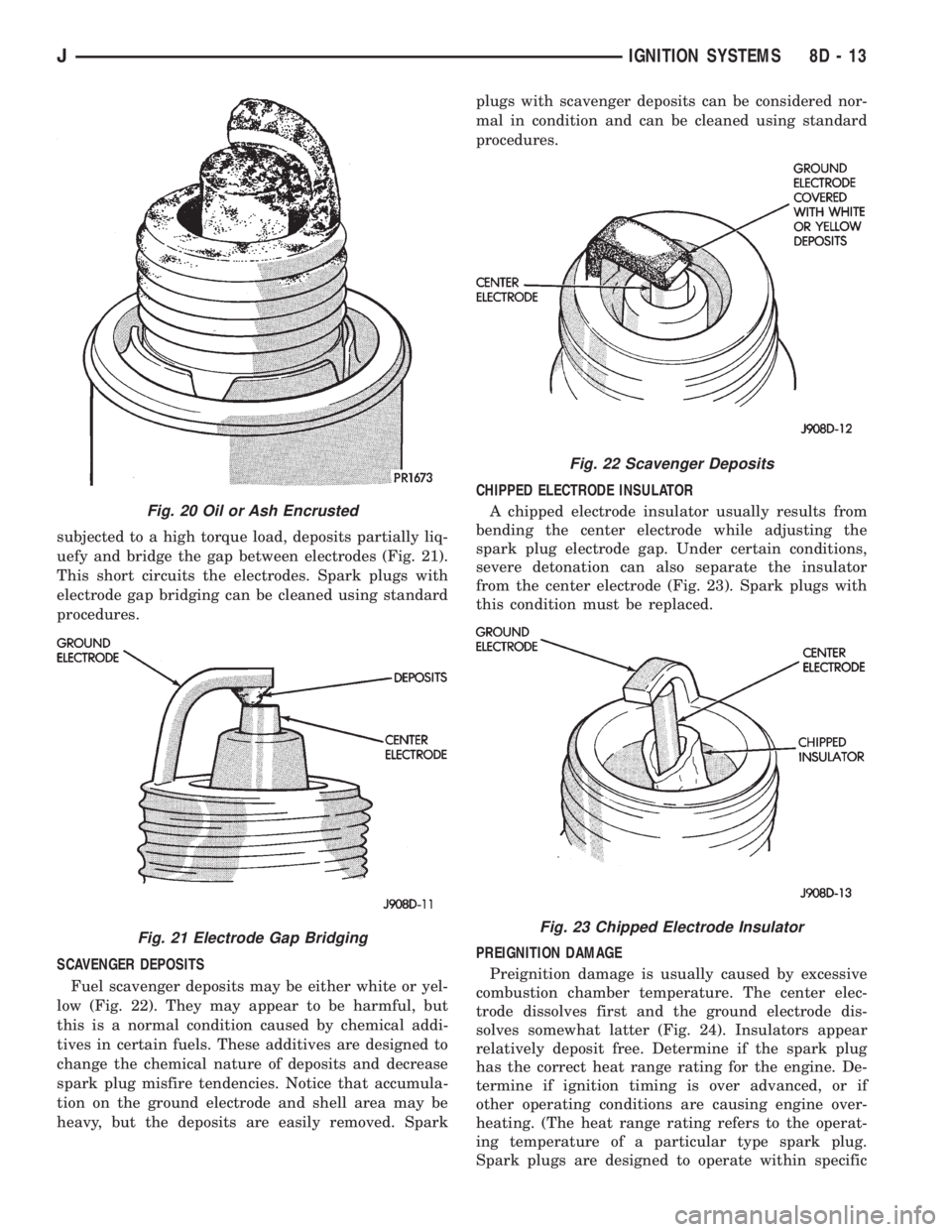
subjected to a high torque load, deposits partially liq-
uefy and bridge the gap between electrodes (Fig. 21).
This short circuits the electrodes. Spark plugs with
electrode gap bridging can be cleaned using standard
procedures.
SCAVENGER DEPOSITS
Fuel scavenger deposits may be either white or yel-
low (Fig. 22). They may appear to be harmful, but
this is a normal condition caused by chemical addi-
tives in certain fuels. These additives are designed to
change the chemical nature of deposits and decrease
spark plug misfire tendencies. Notice that accumula-
tion on the ground electrode and shell area may be
heavy, but the deposits are easily removed. Sparkplugs with scavenger deposits can be considered nor-
mal in condition and can be cleaned using standard
procedures.
CHIPPED ELECTRODE INSULATOR
A chipped electrode insulator usually results from
bending the center electrode while adjusting the
spark plug electrode gap. Under certain conditions,
severe detonation can also separate the insulator
from the center electrode (Fig. 23). Spark plugs with
this condition must be replaced.
PREIGNITION DAMAGE
Preignition damage is usually caused by excessive
combustion chamber temperature. The center elec-
trode dissolves first and the ground electrode dis-
solves somewhat latter (Fig. 24). Insulators appear
relatively deposit free. Determine if the spark plug
has the correct heat range rating for the engine. De-
termine if ignition timing is over advanced, or if
other operating conditions are causing engine over-
heating. (The heat range rating refers to the operat-
ing temperature of a particular type spark plug.
Spark plugs are designed to operate within specific
Fig. 20 Oil or Ash Encrusted
Fig. 21 Electrode Gap Bridging
Fig. 22 Scavenger Deposits
Fig. 23 Chipped Electrode Insulator
JIGNITION SYSTEMS 8D - 13
Page 338 of 2158
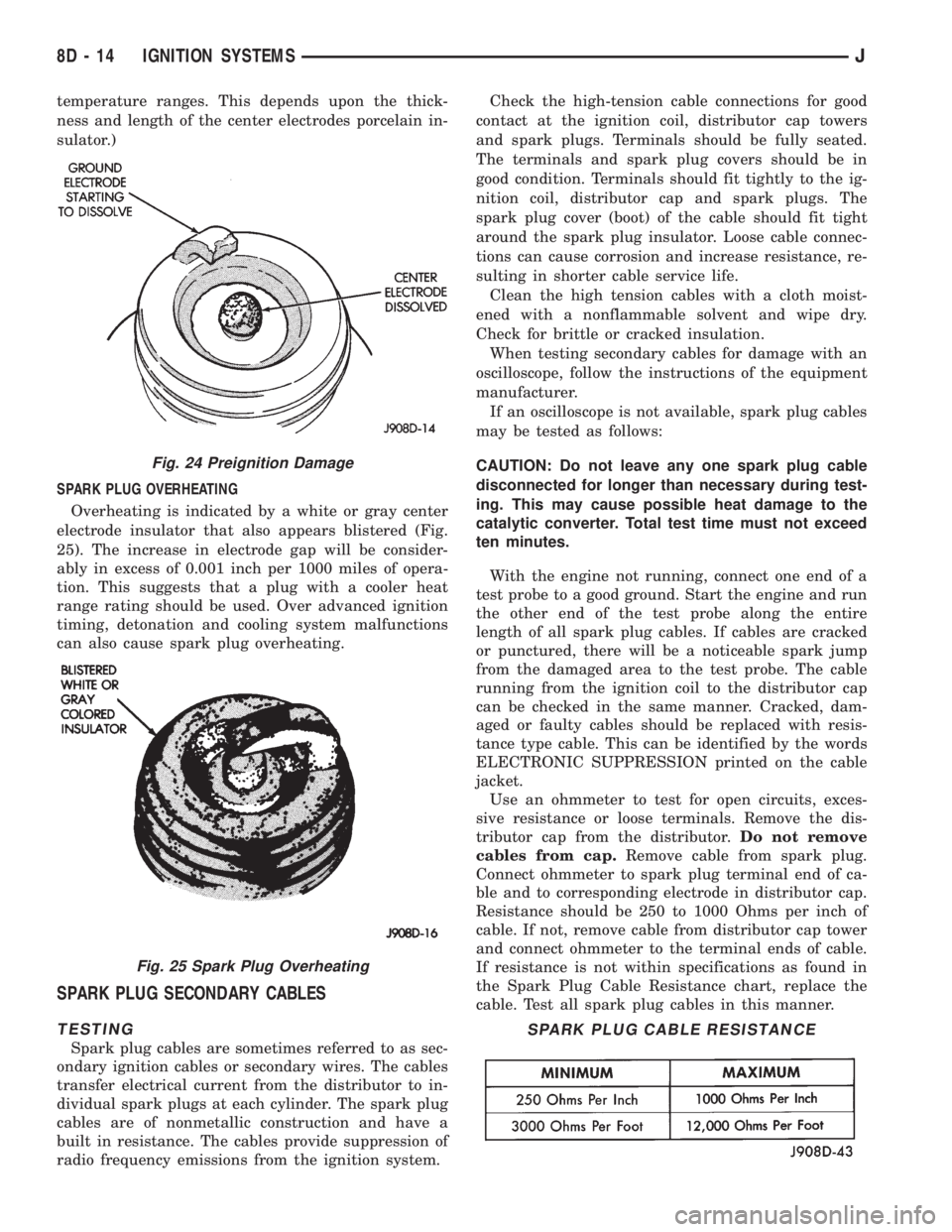
temperature ranges. This depends upon the thick-
ness and length of the center electrodes porcelain in-
sulator.)
SPARK PLUG OVERHEATING
Overheating is indicated by a white or gray center
electrode insulator that also appears blistered (Fig.
25). The increase in electrode gap will be consider-
ably in excess of 0.001 inch per 1000 miles of opera-
tion. This suggests that a plug with a cooler heat
range rating should be used. Over advanced ignition
timing, detonation and cooling system malfunctions
can also cause spark plug overheating.
SPARK PLUG SECONDARY CABLES
TESTING
Spark plug cables are sometimes referred to as sec-
ondary ignition cables or secondary wires. The cables
transfer electrical current from the distributor to in-
dividual spark plugs at each cylinder. The spark plug
cables are of nonmetallic construction and have a
built in resistance. The cables provide suppression of
radio frequency emissions from the ignition system.Check the high-tension cable connections for good
contact at the ignition coil, distributor cap towers
and spark plugs. Terminals should be fully seated.
The terminals and spark plug covers should be in
good condition. Terminals should fit tightly to the ig-
nition coil, distributor cap and spark plugs. The
spark plug cover (boot) of the cable should fit tight
around the spark plug insulator. Loose cable connec-
tions can cause corrosion and increase resistance, re-
sulting in shorter cable service life.
Clean the high tension cables with a cloth moist-
ened with a nonflammable solvent and wipe dry.
Check for brittle or cracked insulation.
When testing secondary cables for damage with an
oscilloscope, follow the instructions of the equipment
manufacturer.
If an oscilloscope is not available, spark plug cables
may be tested as follows:
CAUTION: Do not leave any one spark plug cable
disconnected for longer than necessary during test-
ing. This may cause possible heat damage to the
catalytic converter. Total test time must not exceed
ten minutes.
With the engine not running, connect one end of a
test probe to a good ground. Start the engine and run
the other end of the test probe along the entire
length of all spark plug cables. If cables are cracked
or punctured, there will be a noticeable spark jump
from the damaged area to the test probe. The cable
running from the ignition coil to the distributor cap
can be checked in the same manner. Cracked, dam-
aged or faulty cables should be replaced with resis-
tance type cable. This can be identified by the words
ELECTRONIC SUPPRESSION printed on the cable
jacket.
Use an ohmmeter to test for open circuits, exces-
sive resistance or loose terminals. Remove the dis-
tributor cap from the distributor.Do not remove
cables from cap.Remove cable from spark plug.
Connect ohmmeter to spark plug terminal end of ca-
ble and to corresponding electrode in distributor cap.
Resistance should be 250 to 1000 Ohms per inch of
cable. If not, remove cable from distributor cap tower
and connect ohmmeter to the terminal ends of cable.
If resistance is not within specifications as found in
the Spark Plug Cable Resistance chart, replace the
cable. Test all spark plug cables in this manner.
Fig. 24 Preignition Damage
Fig. 25 Spark Plug Overheating
SPARK PLUG CABLE RESISTANCE
8D - 14 IGNITION SYSTEMSJ
Page 341 of 2158
COMPONENT REMOVAL/INSTALLATION
INDEX
page page
Automatic Shutdown (ASD) Relay............. 17
Camshaft Position Sensor................... 17
Crankshaft Position Sensor.................. 17
Distributor............................... 19
Engine Coolant Temperature Sensor........... 19
General Information....................... 17
Ignition Coil............................. 22Intake Manifold Air Temperature Sensor......... 23
Manifold Absolute Pressure (MAP) Sensor....... 23
Oxygen (O2S) Sensor...................... 23
Powertrain Control Module (PCM)............. 23
Spark Plug Secondary Cables................ 24
Spark Plugs............................. 23
Throttle Position Sensor (TPS)............... 25
GENERAL INFORMATION
This section of the group, Component Removal/In-
stallation, will discuss the removal and installation
of ignition system components.
For basic ignition system diagnostics and service
adjustments, refer to the Diagnostics/Service Proce-
dures section of this group.
For system operation and component identification,
refer to the Component Identification/System Opera-
tion section of this group.
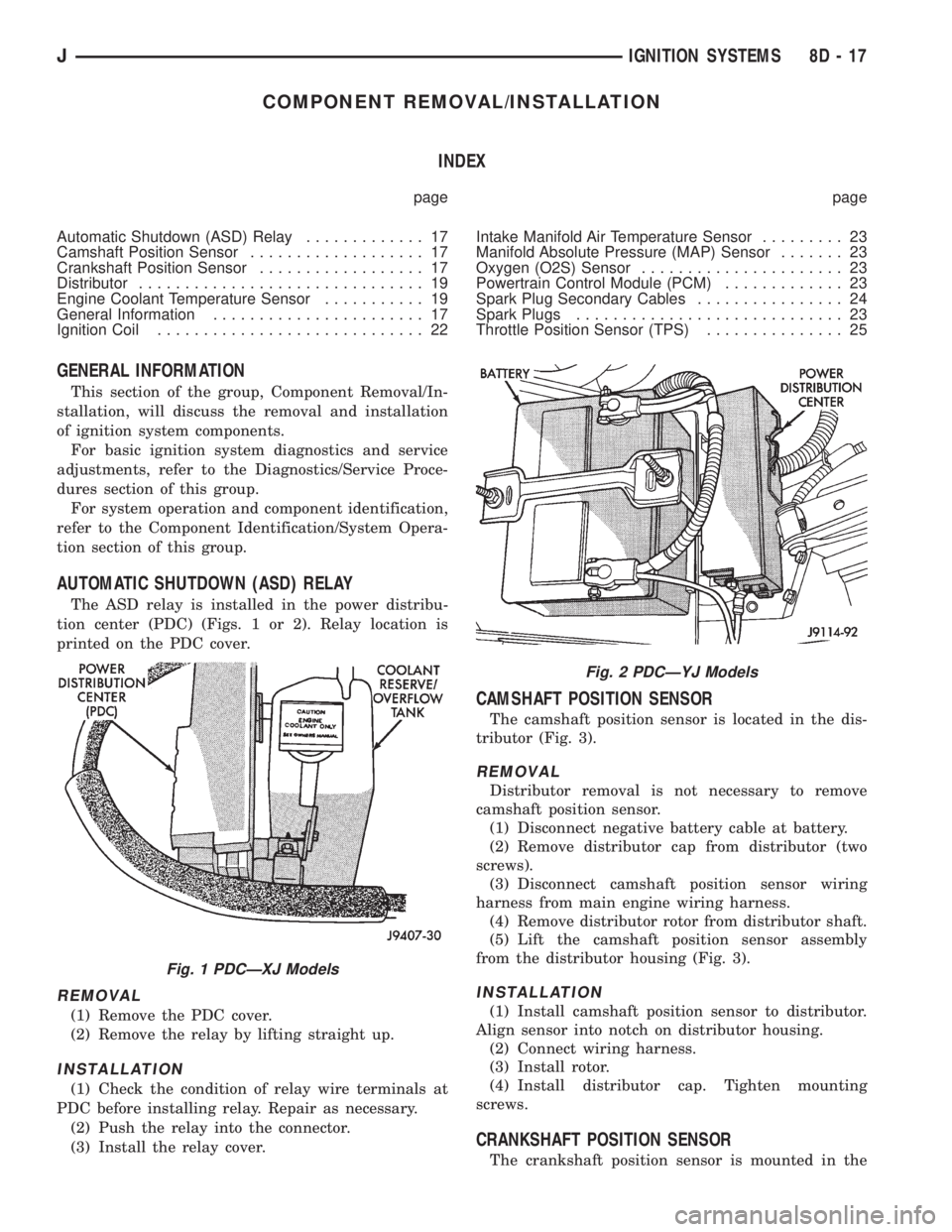
AUTOMATIC SHUTDOWN (ASD) RELAY
The ASD relay is installed in the power distribu-
tion center (PDC) (Figs. 1 or 2). Relay location is
printed on the PDC cover.
REMOVAL
(1) Remove the PDC cover.
(2) Remove the relay by lifting straight up.
INSTALLATION
(1) Check the condition of relay wire terminals at
PDC before installing relay. Repair as necessary.
(2) Push the relay into the connector.
(3) Install the relay cover.
CAMSHAFT POSITION SENSOR
The camshaft position sensor is located in the dis-
tributor (Fig. 3).
REMOVAL
Distributor removal is not necessary to remove
camshaft position sensor.
(1) Disconnect negative battery cable at battery.
(2) Remove distributor cap from distributor (two
screws).
(3) Disconnect camshaft position sensor wiring
harness from main engine wiring harness.
(4) Remove distributor rotor from distributor shaft.
(5) Lift the camshaft position sensor assembly
from the distributor housing (Fig. 3).
INSTALLATION
(1) Install camshaft position sensor to distributor.
Align sensor into notch on distributor housing.
(2) Connect wiring harness.
(3) Install rotor.
(4) Install distributor cap. Tighten mounting
screws.
CRANKSHAFT POSITION SENSOR
The crankshaft position sensor is mounted in the
Fig. 1 PDCÐXJ Models
Fig. 2 PDCÐYJ Models
JIGNITION SYSTEMS 8D - 17
Page 343 of 2158
CAUTION: On some models, two bolts are used to
secure the sensor to the transmission. These bolts
are specially machined to correctly space the unit
to the flywheel. Do not attempt to install any other
bolts.
(3) Connect the electrical connector to the sensor.
(4) Install clip on sensor wire harness.
(5) Install clip over fuel rail mounting stud. Install
clip mounting nut.
INSTALLATIONÐYJ MODELS WITH 4.0L
6-CYLINDER ENGINE AND AUTOMATIC
TRANSMISSION
(1) Install the sensor into the access hole on the
transmission.
(2) Install sensor mounting bolt (Fig. 6).
(3) Tighten sensor mounting bolt to 6-to-8 Nzm (50-
to-70 in. lbs.) torque.
(4) Connect the electrical connector to sensor.
(5) Install the clip to sensor wire harness.
(6) Install clip over fuel rail mounting stud. Install
clip mounting nut.
ENGINE COOLANT TEMPERATURE SENSOR
For an operational description, diagnosis and re-
moval/installation procedures, refer to Group 14,
Fuel System.
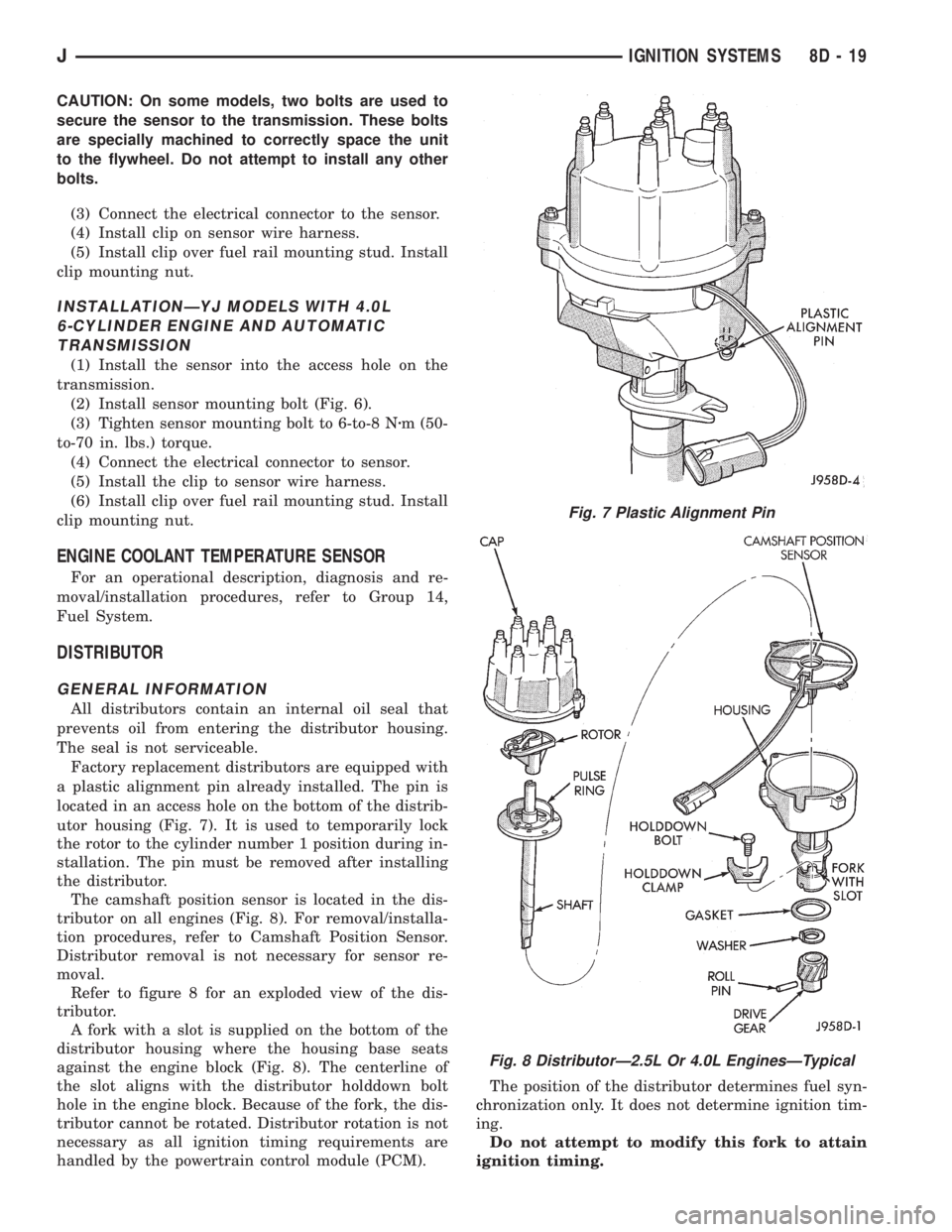
DISTRIBUTOR
GENERAL INFORMATION
All distributors contain an internal oil seal that
prevents oil from entering the distributor housing.
The seal is not serviceable.
Factory replacement distributors are equipped with
a plastic alignment pin already installed. The pin is
located in an access hole on the bottom of the distrib-
utor housing (Fig. 7). It is used to temporarily lock
the rotor to the cylinder number 1 position during in-
stallation. The pin must be removed after installing
the distributor.
The camshaft position sensor is located in the dis-
tributor on all engines (Fig. 8). For removal/installa-
tion procedures, refer to Camshaft Position Sensor.
Distributor removal is not necessary for sensor re-
moval.
Refer to figure 8 for an exploded view of the dis-
tributor.
A fork with a slot is supplied on the bottom of the
distributor housing where the housing base seats
against the engine block (Fig. 8). The centerline of
the slot aligns with the distributor holddown bolt
hole in the engine block. Because of the fork, the dis-
tributor cannot be rotated. Distributor rotation is not
necessary as all ignition timing requirements are
handled by the powertrain control module (PCM).The position of the distributor determines fuel syn-
chronization only. It does not determine ignition tim-
ing.
Do not attempt to modify this fork to attain
ignition timing.
Fig. 7 Plastic Alignment Pin
Fig. 8 DistributorÐ2.5L Or 4.0L EnginesÐTypical
JIGNITION SYSTEMS 8D - 19
Page 347 of 2158
(3) Remove ignition coil mounting bolts (nuts are
used on back side of bracket). Remove coil.
INSTALLATION
(1) Install ignition coil to bracket on cylinder block
with mounting bolts and nuts.
(2) Connect engine harness connector to coil.
(3) Connect ignition coil cable to ignition coil.
INTAKE MANIFOLD AIR TEMPERATURE SENSOR
For an operational description, diagnosis or remov-
al/ installation procedures, refer to Group 14, Fuel
Systems.
MANIFOLD ABSOLUTE PRESSURE (MAP) SENSOR
For an operational description, diagnosis and re-
moval/installation procedures, refer to Group 14,
Fuel System.
OXYGEN (O2S) SENSOR
For an operational description, diagnosis or remov-
al/ installation procedures, refer to Group 14, Fuel
Systems.
POWERTRAIN CONTROL MODULE (PCM)
The PCM was formerly referred to as the SBEC or
engine controller.
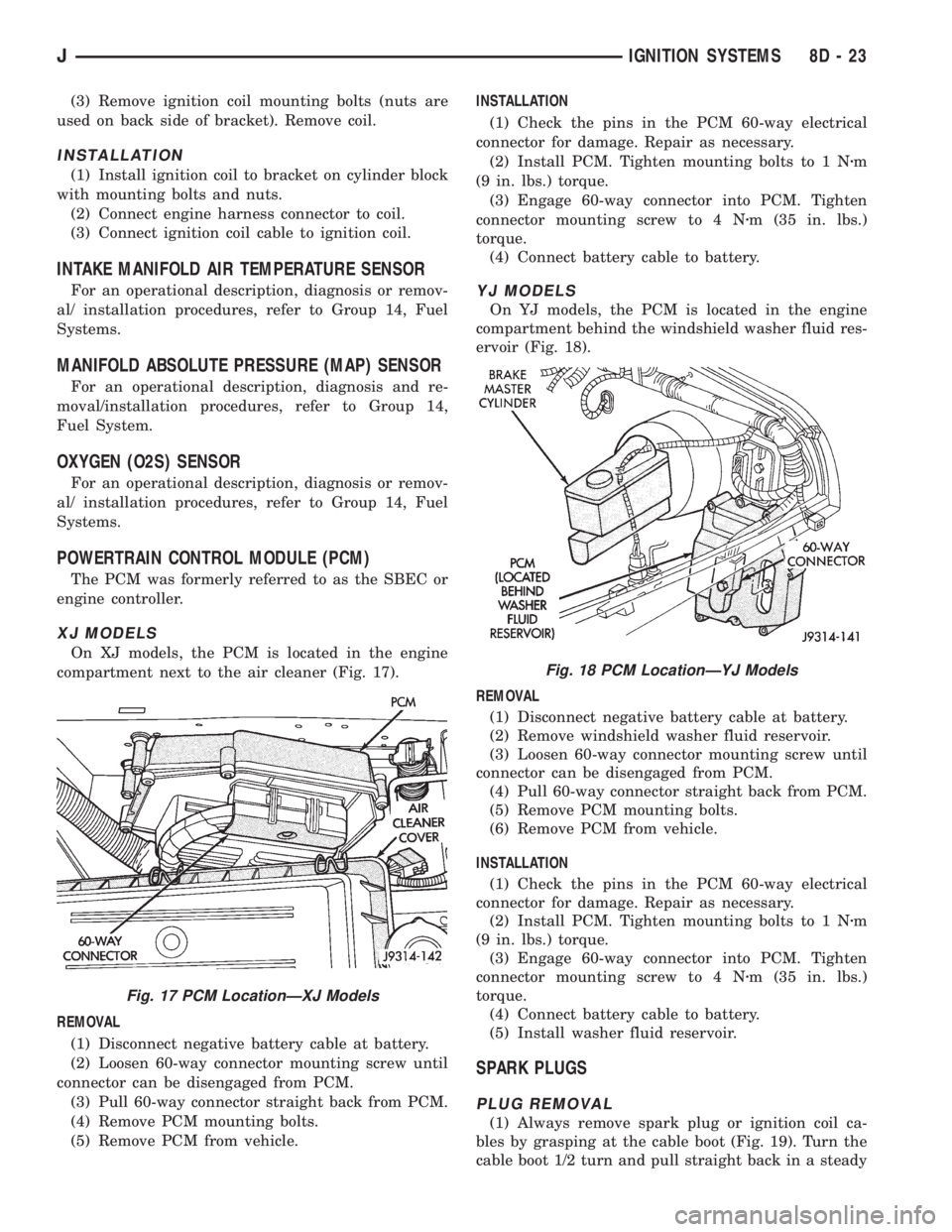
XJ MODELS
On XJ models, the PCM is located in the engine
compartment next to the air cleaner (Fig. 17).
REMOVAL
(1) Disconnect negative battery cable at battery.
(2) Loosen 60-way connector mounting screw until
connector can be disengaged from PCM.
(3) Pull 60-way connector straight back from PCM.
(4) Remove PCM mounting bolts.
(5) Remove PCM from vehicle.INSTALLATION
(1) Check the pins in the PCM 60-way electrical
connector for damage. Repair as necessary.
(2) Install PCM. Tighten mounting bolts to 1 Nzm
(9 in. lbs.) torque.
(3) Engage 60-way connector into PCM. Tighten
connector mounting screw to 4 Nzm (35 in. lbs.)
torque.
(4) Connect battery cable to battery.
YJ MODELS
On YJ models, the PCM is located in the engine
compartment behind the windshield washer fluid res-
ervoir (Fig. 18).
REMOVAL
(1) Disconnect negative battery cable at battery.
(2) Remove windshield washer fluid reservoir.
(3) Loosen 60-way connector mounting screw until
connector can be disengaged from PCM.
(4) Pull 60-way connector straight back from PCM.
(5) Remove PCM mounting bolts.
(6) Remove PCM from vehicle.
INSTALLATION
(1) Check the pins in the PCM 60-way electrical
connector for damage. Repair as necessary.
(2) Install PCM. Tighten mounting bolts to 1 Nzm
(9 in. lbs.) torque.
(3) Engage 60-way connector into PCM. Tighten
connector mounting screw to 4 Nzm (35 in. lbs.)
torque.
(4) Connect battery cable to battery.
(5) Install washer fluid reservoir.
SPARK PLUGS
PLUG REMOVAL
(1) Always remove spark plug or ignition coil ca-
bles by grasping at the cable boot (Fig. 19). Turn the
cable boot 1/2 turn and pull straight back in a steady
Fig. 17 PCM LocationÐXJ Models
Fig. 18 PCM LocationÐYJ Models
JIGNITION SYSTEMS 8D - 23