fuel cap JEEP YJ 1995 Service And Owner's Manual
[x] Cancel search | Manufacturer: JEEP, Model Year: 1995, Model line: YJ, Model: JEEP YJ 1995Pages: 2158, PDF Size: 81.9 MB
Page 1339 of 2158
(6) Remove upper radiator support retaining bolts
and remove radiator support.
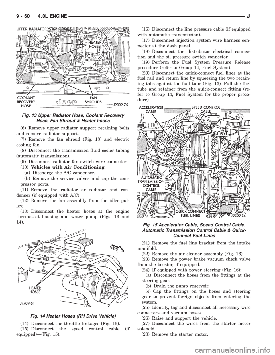
(7) Remove the fan shroud (Fig. 13) and electric
cooling fan.
(8) Disconnect the transmission fluid cooler tubing
(automatic transmission).
(9) Disconnect radiator fan switch wire connector.
(10)Vehicles with Air Conditioning:
(a) Discharge the A/C condenser.
(b) Remove the service valves and cap the com-
pressor ports.
(11) Remove the radiator or radiator and con-
denser (if equipped with A/C).
(12) Remove the fan assembly from the idler pul-
ley.
(13) Disconnect the heater hoses at the engine
thermostat housing and water pump (Figs. 13 and
14).
(14) Disconnect the throttle linkages (Fig. 15).
(15) Disconnect the speed control cable (if
equipped)Ð(Fig. 15).(16) Disconnect the line pressure cable (if equipped
with automatic transmission).
(17) Disconnect injection system wire harness con-
nector at the dash panel.
(18) Disconnect the distributor electrical connec-
tion and the oil pressure switch connector.
(19) Perform the Fuel System Pressure Release
procedure (refer to Group 14, Fuel System).
(20) Disconnect the quick-connect fuel lines at the
fuel rail and return line by squeezing the two retain-
ing tabs against the fuel tube (Fig. 15). Pull the fuel
tube and retainer from the quick-connect fitting (re-
fer to Group 14, Fuel System for the proper proce-
dure).
(21) Remove the fuel line bracket from the intake
manifold.
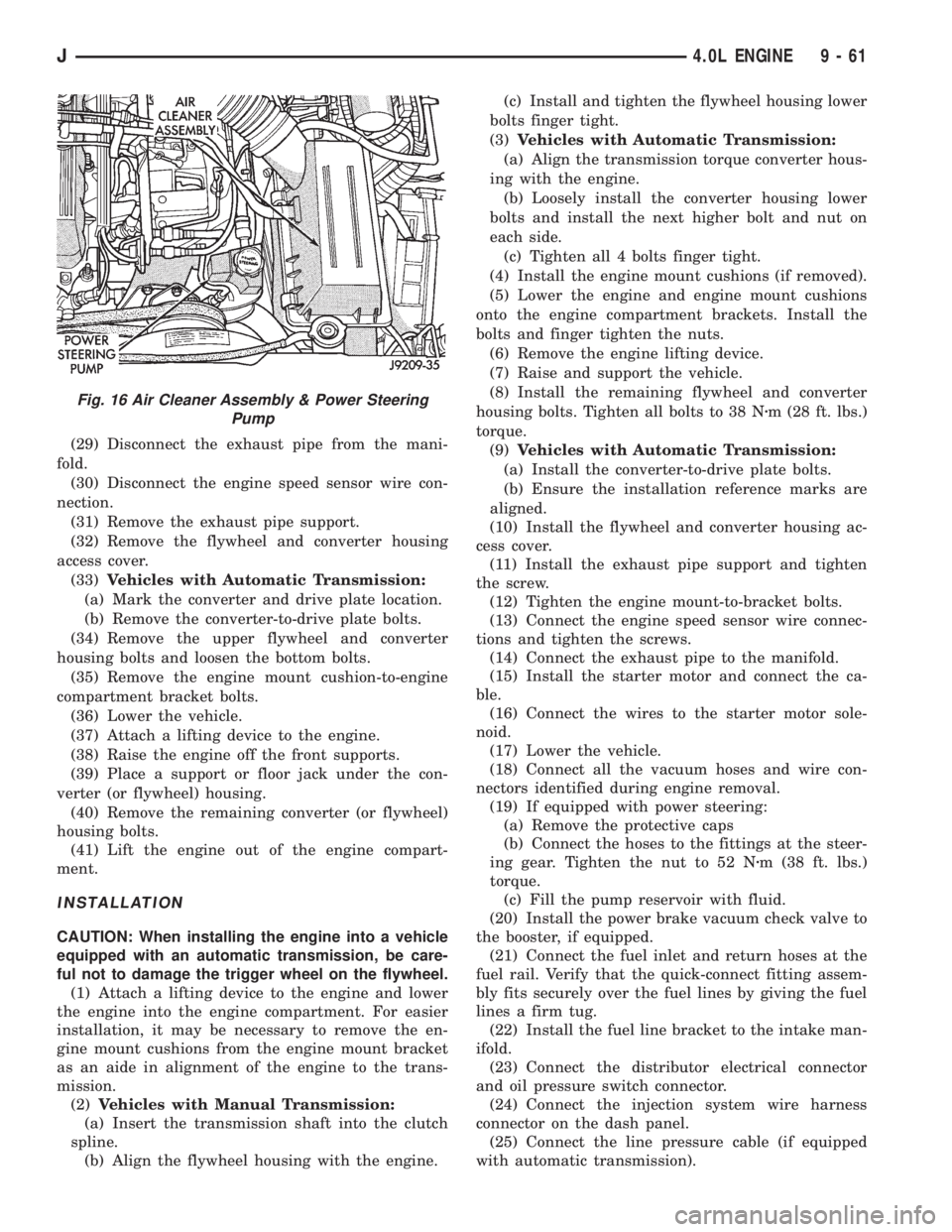
(22) Remove the air cleaner assembly (Fig. 16).
(23) Remove the power brake vacuum check valve
from the booster, if equipped.
(24) If equipped with power steering (Fig. 16):
(a) Disconnect the hoses from the fittings at the
steering gear.
(b) Drain the pump reservoir.
(c) Cap the fittings on the hoses and steering
gear to prevent foreign objects from entering the
system.
(25) Identify, tag and disconnect all necessary wire
connectors and vacuum hoses.
(26) Raise and support the vehicle.
(27) Disconnect the wires from the starter motor
solenoid.
(28) Remove the starter motor.
Fig. 13 Upper Radiator Hose, Coolant Recovery
Hose, Fan Shroud & Heater hoses
Fig. 14 Heater Hoses (RH Drive Vehicle)
Fig. 15 Accelerator Cable, Speed Control Cable,
Automatic Transmission Control Cable & Quick-
Connect Fuel Lines
9 - 60 4.0L ENGINEJ
Page 1340 of 2158
(29) Disconnect the exhaust pipe from the mani-
fold.
(30) Disconnect the engine speed sensor wire con-
nection.
(31) Remove the exhaust pipe support.
(32) Remove the flywheel and converter housing
access cover.
(33)Vehicles with Automatic Transmission:
(a) Mark the converter and drive plate location.
(b) Remove the converter-to-drive plate bolts.
(34) Remove the upper flywheel and converter
housing bolts and loosen the bottom bolts.
(35) Remove the engine mount cushion-to-engine
compartment bracket bolts.
(36) Lower the vehicle.
(37) Attach a lifting device to the engine.
(38) Raise the engine off the front supports.
(39) Place a support or floor jack under the con-
verter (or flywheel) housing.
(40) Remove the remaining converter (or flywheel)
housing bolts.
(41) Lift the engine out of the engine compart-
ment.
INSTALLATION
CAUTION: When installing the engine into a vehicle
equipped with an automatic transmission, be care-
ful not to damage the trigger wheel on the flywheel.
(1) Attach a lifting device to the engine and lower
the engine into the engine compartment. For easier
installation, it may be necessary to remove the en-
gine mount cushions from the engine mount bracket
as an aide in alignment of the engine to the trans-
mission.
(2)Vehicles with Manual Transmission:
(a) Insert the transmission shaft into the clutch
spline.
(b) Align the flywheel housing with the engine.(c) Install and tighten the flywheel housing lower
bolts finger tight.
(3)Vehicles with Automatic Transmission:
(a) Align the transmission torque converter hous-
ing with the engine.
(b) Loosely install the converter housing lower
bolts and install the next higher bolt and nut on
each side.
(c) Tighten all 4 bolts finger tight.
(4) Install the engine mount cushions (if removed).
(5) Lower the engine and engine mount cushions
onto the engine compartment brackets. Install the
bolts and finger tighten the nuts.
(6) Remove the engine lifting device.
(7) Raise and support the vehicle.
(8) Install the remaining flywheel and converter
housing bolts. Tighten all bolts to 38 Nzm (28 ft. lbs.)
torque.
(9)Vehicles with Automatic Transmission:
(a) Install the converter-to-drive plate bolts.
(b) Ensure the installation reference marks are
aligned.
(10) Install the flywheel and converter housing ac-
cess cover.
(11) Install the exhaust pipe support and tighten
the screw.
(12) Tighten the engine mount-to-bracket bolts.
(13) Connect the engine speed sensor wire connec-
tions and tighten the screws.
(14) Connect the exhaust pipe to the manifold.
(15) Install the starter motor and connect the ca-
ble.
(16) Connect the wires to the starter motor sole-
noid.
(17) Lower the vehicle.
(18) Connect all the vacuum hoses and wire con-
nectors identified during engine removal.
(19) If equipped with power steering:
(a) Remove the protective caps
(b) Connect the hoses to the fittings at the steer-
ing gear. Tighten the nut to 52 Nzm (38 ft. lbs.)
torque.
(c) Fill the pump reservoir with fluid.
(20) Install the power brake vacuum check valve to
the booster, if equipped.
(21) Connect the fuel inlet and return hoses at the
fuel rail. Verify that the quick-connect fitting assem-
bly fits securely over the fuel lines by giving the fuel
lines a firm tug.
(22) Install the fuel line bracket to the intake man-
ifold.
(23) Connect the distributor electrical connector
and oil pressure switch connector.
(24) Connect the injection system wire harness
connector on the dash panel.
(25) Connect the line pressure cable (if equipped
with automatic transmission).
Fig. 16 Air Cleaner Assembly & Power Steering
Pump
J4.0L ENGINE 9 - 61
Page 1341 of 2158
(26) Connect the speed control cable, if equipped.
(27) Connect the throttle cable linkages.
(28) Connect the heater hoses at the engine ther-
mostat housing and water pump.
(29) Install the fan assembly to the idler pulley.
(30) Install the radiator or radiator and condenser
(if equipped with A/C).
(31) Connect the service valves to the A/C compres-
sor ports, if equipped with A/C.
(32) Charge the air conditioner system.
(33) Connect radiator fan switch wire.
(34) Connect automatic transmission fluid cooler
lines, if equipped.
(35) Install the fan shroud, electric cooling fan and
radiator and condenser (if equipped with A/C).
(36) Install upper radiator support.
(37) Connect the upper radiator hose.
(38) Connect the lower radiator hose.
(39) Fill the cooling system with reusable coolant
and/or new coolant.
(40) Align the hood to the scribe marks. Install the
hood.
(41) Connect the vacuum harness connector.
(a) Firmly push the connectors together ensuring
that the retaining tabs are engaged.
(b) Insert the vacuum connector assembly into
the retaining bracket on the intake manifold.
(42) Install the air cleaner assembly.
(43) Install the battery and connect the battery ca-
ble.
WARNING: USE EXTREME CAUTION WHEN THE
ENGINE IS OPERATING. DO NOT STAND IN A DI-
RECT LINE WITH THE FAN. DO NOT PUT YOUR
HANDS NEAR THE PULLEYS, BELTS OR FAN. DO
NOT WEAR LOOSE CLOTHING.
(44) Start the engine, inspect for leaks and correct
the fluid levels, as necessary.
ENGINE ASSEMBLYÐYJ VEHICLES
REMOVAL
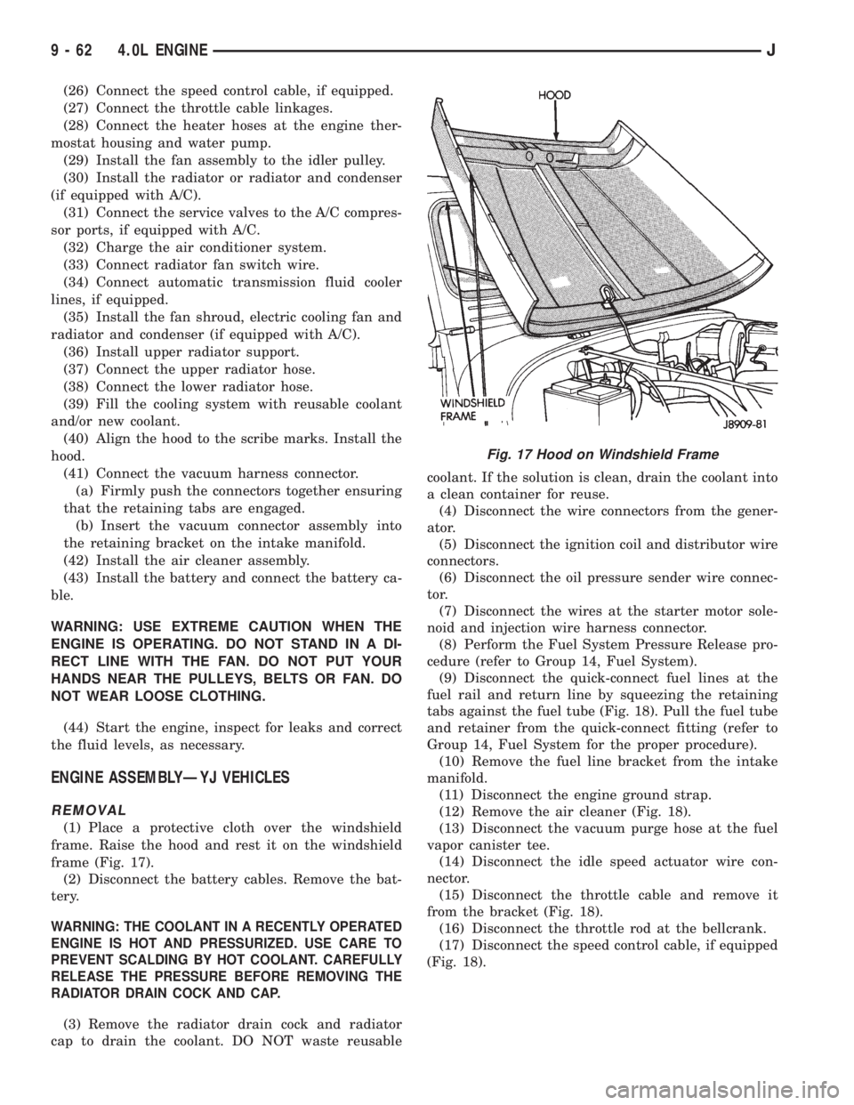
(1) Place a protective cloth over the windshield
frame. Raise the hood and rest it on the windshield
frame (Fig. 17).
(2) Disconnect the battery cables. Remove the bat-
tery.
WARNING: THE COOLANT IN A RECENTLY OPERATED
ENGINE IS HOT AND PRESSURIZED. USE CARE TO
PREVENT SCALDING BY HOT COOLANT. CAREFULLY
RELEASE THE PRESSURE BEFORE REMOVING THE
RADIATOR DRAIN COCK AND CAP.
(3) Remove the radiator drain cock and radiator
cap to drain the coolant. DO NOT waste reusablecoolant. If the solution is clean, drain the coolant into
a clean container for reuse.
(4) Disconnect the wire connectors from the gener-
ator.
(5) Disconnect the ignition coil and distributor wire
connectors.
(6) Disconnect the oil pressure sender wire connec-
tor.
(7) Disconnect the wires at the starter motor sole-
noid and injection wire harness connector.
(8) Perform the Fuel System Pressure Release pro-
cedure (refer to Group 14, Fuel System).
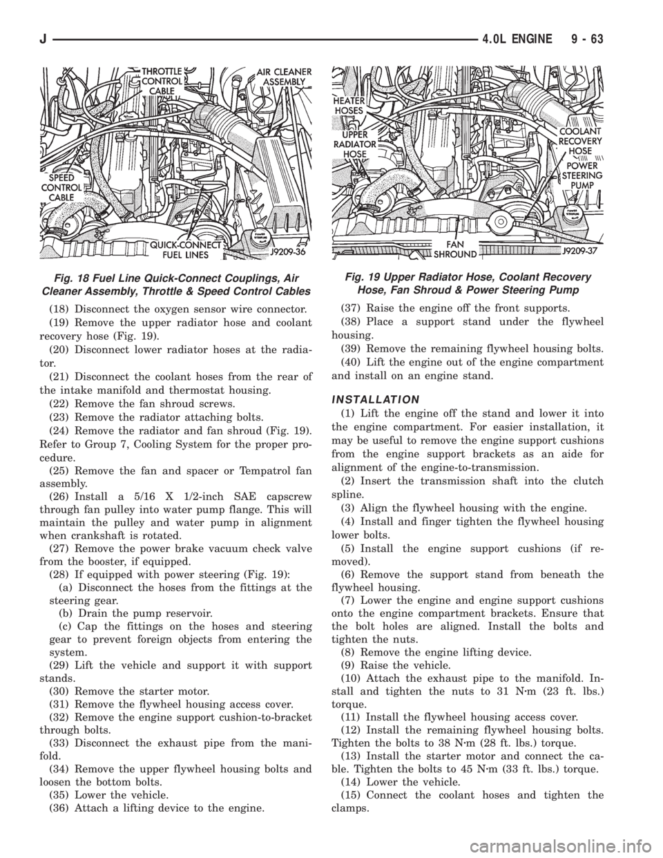
(9) Disconnect the quick-connect fuel lines at the
fuel rail and return line by squeezing the retaining
tabs against the fuel tube (Fig. 18). Pull the fuel tube
and retainer from the quick-connect fitting (refer to
Group 14, Fuel System for the proper procedure).
(10) Remove the fuel line bracket from the intake
manifold.
(11) Disconnect the engine ground strap.
(12) Remove the air cleaner (Fig. 18).
(13) Disconnect the vacuum purge hose at the fuel
vapor canister tee.
(14) Disconnect the idle speed actuator wire con-
nector.
(15) Disconnect the throttle cable and remove it
from the bracket (Fig. 18).
(16) Disconnect the throttle rod at the bellcrank.
(17) Disconnect the speed control cable, if equipped
(Fig. 18).
Fig. 17 Hood on Windshield Frame
9 - 62 4.0L ENGINEJ
Page 1342 of 2158
(18) Disconnect the oxygen sensor wire connector.
(19) Remove the upper radiator hose and coolant
recovery hose (Fig. 19).
(20) Disconnect lower radiator hoses at the radia-
tor.
(21) Disconnect the coolant hoses from the rear of
the intake manifold and thermostat housing.
(22) Remove the fan shroud screws.
(23) Remove the radiator attaching bolts.
(24) Remove the radiator and fan shroud (Fig. 19).
Refer to Group 7, Cooling System for the proper pro-
cedure.
(25) Remove the fan and spacer or Tempatrol fan
assembly.
(26) Install a 5/16 X 1/2-inch SAE capscrew
through fan pulley into water pump flange. This will
maintain the pulley and water pump in alignment
when crankshaft is rotated.
(27) Remove the power brake vacuum check valve
from the booster, if equipped.
(28) If equipped with power steering (Fig. 19):
(a) Disconnect the hoses from the fittings at the
steering gear.
(b) Drain the pump reservoir.
(c) Cap the fittings on the hoses and steering
gear to prevent foreign objects from entering the
system.
(29) Lift the vehicle and support it with support
stands.
(30) Remove the starter motor.
(31) Remove the flywheel housing access cover.
(32) Remove the engine support cushion-to-bracket
through bolts.
(33) Disconnect the exhaust pipe from the mani-
fold.
(34) Remove the upper flywheel housing bolts and
loosen the bottom bolts.
(35) Lower the vehicle.
(36) Attach a lifting device to the engine.(37) Raise the engine off the front supports.
(38) Place a support stand under the flywheel
housing.
(39) Remove the remaining flywheel housing bolts.
(40) Lift the engine out of the engine compartment
and install on an engine stand.
INSTALLATION
(1) Lift the engine off the stand and lower it into
the engine compartment. For easier installation, it
may be useful to remove the engine support cushions
from the engine support brackets as an aide for
alignment of the engine-to-transmission.
(2) Insert the transmission shaft into the clutch
spline.
(3) Align the flywheel housing with the engine.
(4) Install and finger tighten the flywheel housing
lower bolts.
(5) Install the engine support cushions (if re-
moved).
(6) Remove the support stand from beneath the
flywheel housing.
(7) Lower the engine and engine support cushions
onto the engine compartment brackets. Ensure that
the bolt holes are aligned. Install the bolts and
tighten the nuts.
(8) Remove the engine lifting device.
(9) Raise the vehicle.
(10) Attach the exhaust pipe to the manifold. In-
stall and tighten the nuts to 31 Nzm (23 ft. lbs.)
torque.
(11) Install the flywheel housing access cover.
(12) Install the remaining flywheel housing bolts.
Tighten the bolts to 38 Nzm (28 ft. lbs.) torque.
(13) Install the starter motor and connect the ca-
ble. Tighten the bolts to 45 Nzm (33 ft. lbs.) torque.
(14) Lower the vehicle.
(15) Connect the coolant hoses and tighten the
clamps.
Fig. 18 Fuel Line Quick-Connect Couplings, Air
Cleaner Assembly, Throttle & Speed Control CablesFig. 19 Upper Radiator Hose, Coolant Recovery
Hose, Fan Shroud & Power Steering Pump
J4.0L ENGINE 9 - 63
Page 1343 of 2158
(16) Remove the pulley-to-water pump flange
alignment capscrew and install the fan and spacer or
Tempatrol fan assembly.
(17) Tighten the serpentine drive belt according to
the specifications listed in Group 7, Cooling System.
(18) Install the fan shroud and radiator (refer to
Group 7, Cooling System for the proper procedure).
(19) Connect the radiator hoses.
(20) Connect the throttle valve rod and retainer.
(21) Connect the throttle cable and install the rod.
(22) Install the throttle valve rod spring.
(23) Connect the speed control cable, if equipped.
(24) Connect the oxygen sensor wire connector.
(25) Install the vacuum hose and check valve on
the brake booster.
(26) Connect the coolant temperature sensor wire
connector.
(27) Connect the idle speed actuator wire connec-
tor.
(28) Connect the fuel inlet and return hoses at the
fuel rail. Verify that the quick-connect fitting assem-
bly fits securely over the fuel lines by giving the fuel
lines a firm tug.
(29) Install the fuel line bracket to the intake man-
ifold.
(30) Connect all fuel injection wire connections.
(31) Install the engine ground strap.
(32) Connect the ignition coil wire connector.
(33) Remove the coolant temperature sending unit
to permit air to escape from the block. Fill the cool-
ing system with coolant. Install the coolant tempera-
ture sending unit when the system is filled.
(34) If equipped with power steering:
(a) Remove the protective caps
(b) Connect the hoses to the fittings at the steer-
ing gear. Tighten the nut to 52 Nzm (38 ft. lbs.)
torque.
(c) Fill the pump reservoir with fluid.
(35) Install the battery and connect the battery ca-
bles.
(36) Install the air cleaner bonnet to the throttle
body.
(37) Install the air cleaner.
(38) Lower the hood and secure in place.
(39) Start the engine and inspect for leaks.
(40) Stop the engine and check the fluid levels.
Add fluid, as required.
ENGINE CYLINDER HEAD COVER
A cured gasket is part of the engine cylinder head
cover.
REMOVAL
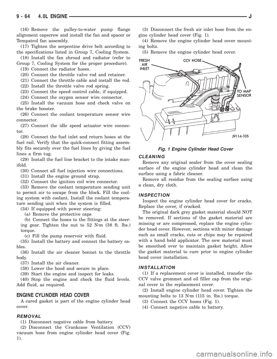
(1) Disconnect negative cable from battery.
(2) Disconnect the Crankcase Ventilation (CCV)
vacuum hose from engine cylinder head cover (Fig.
1).(3) Disconnect the fresh air inlet hose from the en-
gine cylinder head cover (Fig. 1).
(4) Remove the engine cylinder head cover mount-
ing bolts.
(5) Remove the engine cylinder head cover.
CLEANING
Remove any original sealer from the cover sealing
surface of the engine cylinder head and clean the
surface using a fabric cleaner.
Remove all residue from the sealing surface using
a clean, dry cloth.
INSPECTION
Inspect the engine cylinder head cover for cracks.
Replace the cover, if cracked.
The original dark grey gasket material should NOT
be removed. If sections of the gasket material are
missing or are compressed, replace the engine cylin-
der head cover. However, sections with minor damage
such as small cracks, cuts or chips may be repaired
with a hand held applicator. The new material must
be smoothed over to maintain gasket height. Allow
the gasket material to cure prior to engine cylinder
head cover installation.
INSTALLATION
(1) If a replacement cover is installed, transfer the
CCV valve grommet and oil filler cap from the origi-
nal cover to the replacement cover.
(2) Install engine cylinder head cover. Tighten the
mounting bolts to 13 Nzm (115 in. lbs.) torque.
(3) Connect the CCV hoses (Fig. 1).
(4) Connect negative cable to battery.
Fig. 1 Engine Cylinder Head Cover
9 - 64 4.0L ENGINEJ
Page 1348 of 2158
counter bolts which were painted in an earlier ser-
vice operation, replace them.
(6) Install the ignition coil and bracket assembly.
(7) Connect the temperature sending unit wire
connector.
(8) Install the spark plugs and tighten to 37 Nzm
(27 ft. lbs.) torque. Connect the ignition wires.
(9) Install the intake and engine exhaust mani-
folds (refer to Group 11, Exhaust System and Intake
Manifold for the proper procedures).
(10) Install the fuel lines and the vacuum advance
hose.
(11) If equipped, attach the power steering pump
and bracket.
(12) Install the push rods, rocker arms, pivots and
bridges in the order they were removed (refer to
Rocker Arms and Push Rods in this section).
(13) Install the engine cylinder head cover.
(14) Attach the air conditioner compressor mount-
ing bracket to the engine cylinder head and block.
Tighten the bolts to 40 Nzm (30 ft. lbs.) torque.
(15) Attach the air conditioning compressor to the
bracket. Tighten the bolts to 27 Nzm (20 ft. lbs.)
torque.
CAUTION: The serpentine drive belt must be routed
correctly. Incorrect routing can cause the water
pump to turn in the opposite direction causing the
engine to overheat.
(16) Install the serpentine drive belt and correctly
tension the belt (refer to Group 7, Cooling System for
the proper procedure).
(17) Install the air cleaner and ducting.
(18) Install the engine cylinder head cover.
(19) Connect the hoses to the engine thermostat
housing and fill the cooling system to the specified
level (refer to Group 7, Cooling Systems for the
proper procedure).
(20) The automatic transmission throttle linkage
and cable must be adjusted after completing the en-
gine cylinder head installation (refer to Group 21,
Transmissions for the proper procedures).(21) Install the temperature sending unit and con-
nect the wire connector.
(22) Connect the fuel line.
(23) Connect negative cable to battery.
(24) Connect the upper radiator hose and heater
hose at the engine thermostat housing.
(25) Fill the cooling system. Check for leaks.
WARNING: USE EXTREME CAUTION WHEN THE
ENGINE IS OPERATING. DO NOT STAND IN DIRECT
LINE WITH THE FAN. DO NOT PUT HANDS NEAR
THE PULLEYS, BELTS OR FAN. DO NOT WEAR
LOOSE CLOTHING.
(26) Operate the engine with the radiator cap off.
Inspect for leaks and continue operating the engine
until the engine thermostat opens. Add coolant, if re-
quired.
VALVES AND VALVE SPRINGS
This procedure is done with the engine cylinder
head removed from the block.
REMOVAL
(1) Remove the engine cylinder head from the cyl-
inder block.
(2) Use Valve Spring Compressor Tool
MD-998772A and compress each valve spring.
(3) Remove the valve locks, retainers, springs and
valve stem oil seals. Discard the oil seals.
(4) Use an Arkansas smooth stone or a jewelers
file to remove any burrs on the top of the valve stem,
especially around the groove for the locks.
(5) Remove the valves, and place them in a rack in
the same order as removed.
VALVE CLEANING
Clean all carbon deposits from the combustion
chambers, valve ports, valve stems, valve stem
guides and head.
Clean all grime and gasket material from the en-
gine cylinder head machined gasket surface.
INSPECTION
Inspect for cracks in the combustion chambers and
valve ports.
Inspect for cracks on the exhaust seat.
Inspect for cracks in the gasket surface at each
coolant passage.
Inspect valves for burned, cracked or warped
heads.
Inspect for scuffed or bent valve stems.
Replace valves displaying any damage.
VALVE REFACING
(1) Use a valve refacing machine to reface the in-
take and exhaust valves to the specified angle.
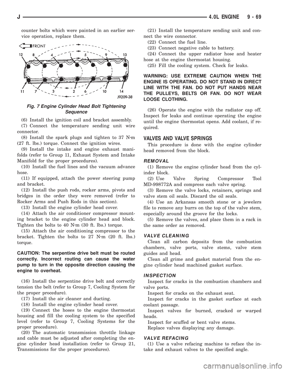
Fig. 7 Engine Cylinder Head Bolt Tightening
Sequence
J4.0L ENGINE 9 - 69
Page 1382 of 2158
INSTALLATION
(1) Install the muffler onto the catalytic converter
outlet. Ensure that the locator on the converter
aligns with the notch on the muffler, if so equipped.
Install the clamp and tighten the nuts finger tight.
(2) Install the exhaust tailpipe into the muffler
outlet. Ensure that the locator on the exhaust
tailpipe aligns with the notch on the muffler, if so
equipped. Install the clamp and tighten the nuts fin-
ger tight.
(3) Install the front exhaust tailpipe supports and
the rear exhaust tailpipe hanger. Ensure that the ex-
haust tailpipe has sufficient clearance from the floor
pan and shields.
(4) Tighten the nuts on the muffler-to-catalytic
converter and the muffler-to-exhaust tailpipe clamps
to 61 Nzm (45 ft. lbs.) torque.
(5) Lower the vehicle.
(6) Start the engine and inspect for exhaust leaks
and contact with the body panels and shields.
ENGINE EXHAUST MANIFOLDÐ2.5L ENGINE
REMOVAL
(1) Disconnect the battery negative cable.
(2) Remove all components attached to the intake
manifold.
(3) Raise the vehicle.
(4) Disconnect the exhaust pipe from the engine
exhaust manifold.
(5) Lower the vehicle.
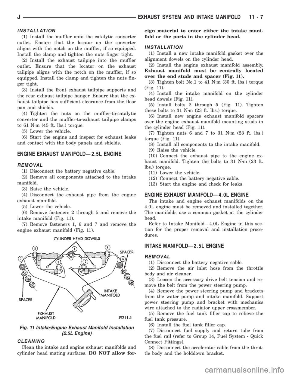
(6) Remove fasteners 2 through 5 and remove the
intake manifold (Fig. 11).
(7) Remove fasteners 1, 6 and 7 and remove the
engine exhaust manifold (Fig. 11).
CLEANING
Clean the intake and engine exhaust manifolds and
cylinder head mating surfaces.DO NOT allow for-eign material to enter either the intake mani-
fold or the ports in the cylinder head.
INSTALLATION
(1) Install a new intake manifold gasket over the
alignment dowels on the cylinder head.
(2) Install the engine exhaust manifold assembly.
Exhaust manifold must be centrally located
over the end studs and spacer (Fig. 11).
(3) Tighten bolt No.1 to 41 Nzm (30 ft. lbs.) torque
(Fig. 11).
(4) Install the intake manifold on the cylinder
head dowels (Fig. 11).
(5) Install bolts 2 through 5 (Fig. 11). Tighten
these bolts to 31 Nzm (23 ft. lbs.) torque.
(6) Install new engine exhaust manifold spacers
over the engine exhaust manifold mounting studs in
the cylinder head (Fig. 11).
(7) Tighten nuts 6 and 7 to 31 Nzm (23 ft. lbs.)
torque (Fig. 11).
(8) Install all components to the intake manifold.
(9) Raise the vehicle.
(10) Connect the exhaust pipe to the engine ex-
haust manifold. Tighten the bolts to 31 Nzm (23 ft.
lbs.) torque.
(11) Lower the vehicle.
(12) Connect the battery negative cable.
(13) Start the engine and check for leaks.
ENGINE EXHAUST MANIFOLDÐ4.0L ENGINE
The intake and engine exhaust manifolds on the
4.0L engine must be removed and installed together.
The manifolds use a common gasket at the cylinder
head.
Refer to Intake ManifoldÐ4.0L Engine in this sec-
tion for the proper removal and installation proce-
dures.
INTAKE MANIFOLDÐ2.5L ENGINE
REMOVAL
(1) Disconnect the battery negative cable.
(2) Remove the air inlet hose from the throttle
body and air cleaner.
(3) Loosen the accessory drive belt tension and re-
move the belt from the power steering pump.
(4) Remove the power steering pump and brackets
from the water pump and intake manifold. Support
power steering pump and bracket with mechanics
wire attached to the radiator upper crossmember.
(5) Remove the fuel tank filler cap to relieve the
fuel tank pressure.
(6) Install the fuel tank filler cap.
(7) Disconnect fuel supply and return tube from
the fuel rail (refer to Group 14, Fuel System - Quick
Connect Fittings).
(8) Disconnect the accelerator cable from the throt-
tle body and the holddown bracket.
Fig. 11 Intake/Engine Exhaust Manifold Installation
(2.5L Engine)
JEXHAUST SYSTEM AND INTAKE MANIFOLD 11 - 7
Page 1403 of 2158
FUEL SYSTEM
CONTENTS
page page
ACCELERATOR PEDAL AND THROTTLE CABLE.17
FUEL DELIVERY SYSTEM.................. 3
FUEL TANKS........................... 13
GENERAL INFORMATION.................. 1
MULTI-PORT FUEL INJECTION (MFI)Ð
COMPONENT DESCRIPTION/SYSTEMOPERATION.......................... 19
MULTI-PORT FUEL INJECTION (MFI)Ð
COMPONENT REMOVAL/INSTALLATION.... 58
MULTI-PORT FUEL INJECTION (MFI)Ð
GENERAL DIAGNOSIS.................. 35
SPECIFICATIONS........................ 67
GENERAL INFORMATION
Throughout this group, references are made to par-
ticular vehicle models by alphabetical designation
(XJ or YJ) or by the particular vehicle nameplate. A
chart showing a breakdown of the alphabetical desig-
nations is included in the Introduction section at the
beginning of this manual.
TheFuel Systemconsists of: the fuel tank, an
electric (fuel tank mounted) fuel pump and a fuel fil-
ter. It also consists of fuel tubes/lines/hoses, vacuum
hoses, throttle body and fuel injectors.
TheFuel Delivery Systemconsists of: the electric
fuel pump, fuel filter, fuel tubes/lines/hoses, fuel rail,
fuel injectors and fuel pressure regulator.
AFuel Return Systemis used on all vehicles.
The system consists of: the fuel tubes/lines/hoses that
route fuel back to the fuel tank.
TheFuel Tank Assemblyconsists of: the fuel
tank, filler tube, fuel fill and vent hoses, fuel gauge
sending unit/electric fuel pump module, a pressure
relief/rollover valve and a pressure-vacuum filler cap.
Also to be considered part of the fuel system is the
Evaporation Control System.This is designed to
reduce the emission of fuel vapors into the atmo-
sphere. The description and function of the Evapora-
tive Control System is found in Group 25, Emission
Control Systems.
FUEL USAGE STATEMENT
Your vehicle was designed to meet all emission reg-
ulations and provide excellent fuel economy using
high quality unleaded gasoline. Only use unleaded
gasolines having a minimum posted octane of 87.
If your vehicle develops occasional light spark
knock (ping) at low engine speeds, this is not harm-
ful. However,continued heavy knock at high
speeds can cause damage and should be re-
ported to your dealer immediately.Engine dam-
age as a result of heavy knock operation may not becovered by the new vehicle warranty.
In addition to using unleaded gasoline with the
proper octane rating,those that contain deter-
gents, corrosion and stability additives are rec-
ommended.Using gasolines that have these
additives will help improve fuel economy, reduce
emissions and maintain vehicle performance.
Poor quality gasolinecan cause problems such
as hard starting, stalling and stumble. If you experi-
ence these problems, use another brand of gasoline
before considering service for the vehicle.
GASOLINE/OXYGENATE BLENDS
Some fuel suppliers blend unleaded gasoline with
materials that contain oxygen such as alcohol, MTBE
and ETBE. The type and amount of oxygenate used
in the blend is important. The following are generally
used in gasoline blends:
ETHANOL
Ethanol (Ethyl or Grain Alcohol) properly blended,
is used as a mixture of 10 percent ethanol and 90
percent gasoline.Gasoline with ethanol may be
used in your vehicle.
METHANOL
CAUTION: DO NOT USE GASOLINES CONTAINING
METHANOL.Use of methanol/gasoline blends may re-
sult in starting and driveability problems. In addition,
damage may be done to critical fuel system compo-
nents.
Methanol (Methyl or Wood Alcohol) is used in a va-
riety of concentrations blended with unleaded gaso-
JFUEL SYSTEM 14 - 1
Page 1405 of 2158
FUEL DELIVERY SYSTEM
INDEX
page page
Fuel Filter................................ 9
Fuel Pressure Leak Down Test................ 8
Fuel Pressure Release Procedure.............. 6
Fuel Pump Capacity Test.................... 7
Fuel Pump Electrical Control.................. 5Fuel Pump Module......................... 3
Fuel System Pressure Test................... 6
Fuel Tubes/Lines/Hoses and Clamps............ 9
Quick-Connect Fittings..................... 10
FUEL PUMP MODULE
The fuel pump module is installed in the top of the
fuel tank. The fuel pump module contains the follow-
ing components:
²Electric fuel pump
²Fuel pump reservoir
²In-tank fuel filter
²Fuel gauge sending unit
²Fuel supply and return tube connections
The fuel pump used on all vehicles is a turbine
type pump. It is driven by a permanent magnet 12
volt electric motor that is immersed in the fuel tank.
The electrical pump is integral with the fuel sender
unit. The pump/sender assembly is installed inside
the fuel tank.
The fuel pump has a check valve at the outlet end
that consists of a ball held against a seat by force ap-
plied from a spring. When the pump is operating,
fuel pressure overcomes spring pressure and forces
the ball off its seat, allowing fuel to flow. When the
pump is not operating, spring pressure forces the ball
back against the seat preventing fuel backflow
through the pump.
Fuel system pressure is maintained at approxi-
mately 214 kPa (31 psi). This is when the pump is
operating and vacuum is supplied to the fuel pres-
sure regulator. If vacuum is not supplied to the pres-
sure regulator, fuel pressure will be approximately
55-69 kPa (8-10 psi) higher. This may be due to a
broken or clogged vacuum line. When the fuel pump
is not operating, fuel system pressure of 131-269 kPa
(19-39 psi) is maintained for approximately 2 to 6
hours. This is done by the fuel pump outlet check
valve and the vacuum assisted fuel pressure regula-
tor.
REMOVALÐXJ MODELS
The fuel pump/gauge sender unit assembly can be
removed from the fuel tank without removing the
tank from the vehicle.
WARNING: THE FUEL SYSTEM IS UNDER A CON-
STANT PRESSURE (EVEN WITH THE ENGINE OFF).
BEFORE SERVICING THE FUEL PUMP MODULE,
THE FUEL SYSTEM PRESSURE MUST BE RE-LEASED. REFER TO THE FUEL PRESSURE RE-
LEASE PROCEDURE IN THIS GROUP.
WARNING: EXTINGUISH ALL TOBACCO SMOKING
PRODUCTS BEFORE SERVICING THE FUEL SYS-
TEM. KEEP OPEN FLAME AWAY FROM FUEL SYS-
TEM COMPONENTS.
(1) Remove fuel filler cap. Perform the Fuel Pres-
sure Release Procedure as outlined in this group.
(2) Disconnect negative battery cable.
(3) Using an approved portable gasoline siphon/
storage tank, drain fuel tank until fuel level is below
one quarter (1/4) full.
(4) Raise and support vehicle.
WARNING: WRAP SHOP TOWELS AROUND FUEL
HOSES TO ABSORB ANY FUEL SPILLAGE DURING
FUEL TANK REMOVAL.
(5) Disconnect fuel vent supply and return tubes
from fittings on fuel pump module.
(6) Disconnect fuel pump module electrical harness
connector from main harness.
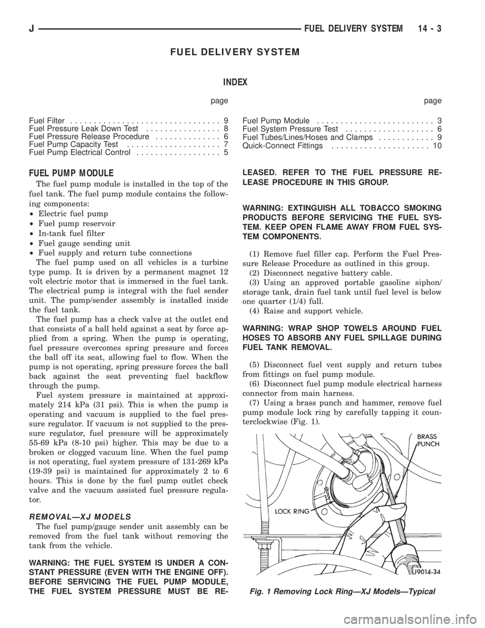
(7) Using a brass punch and hammer, remove fuel
pump module lock ring by carefully tapping it coun-
terclockwise (Fig. 1).
Fig. 1 Removing Lock RingÐXJ ModelsÐTypical
JFUEL DELIVERY SYSTEM 14 - 3
Page 1406 of 2158
(8) Remove fuel pump module and O-ring seal.
Discard old O-ring and fuel pump module inlet filter.
DISASSEMBLYÐXJ MODELS
(1) Remove and discard fuel pump inlet filter.
The wire terminals to the fuel pump motor are dif-
ferent in size and cannot be connected to the wrong
terminal.
(2) Disconnect fuel pump terminal wires.
(3) Remove fuel pump outlet hose and clamp. Re-
place the hose if it shows any signs of fatigue or fail-
ure.
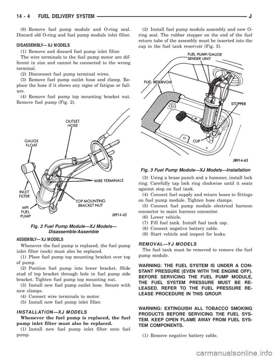
(4) Remove fuel pump top mounting bracket nut.
Remove fuel pump (Fig. 2).
ASSEMBLYÐXJ MODELS
Whenever the fuel pump is replaced, the fuel pump
inlet filter (sock) must also be replaced.
(1) Place fuel pump top mounting bracket over top
of pump.
(2) Position fuel pump into lower bracket. Slide
stud of top bracket through hole in fuel pump side
bracket. Tighten fuel pump top mounting nut.
(3) Install new fuel pump outlet hose. Secure with
new clamps.
(4) Connect wire terminals to motor.
(5) Install new fuel pump inlet filter.
INSTALLATIONÐXJ MODELS
Whenever the fuel pump is replaced, the fuel
pump inlet filter must also be replaced.
(1) Install new fuel pump inlet filter onto fuel
pump.(2) Install fuel pump module assembly and new O-
ring seal. The rubber stopper on the end of the fuel
return tube of the assembly must be inserted into the
cup in the fuel tank reservoir (Fig. 3).
(3) Using a brass punch and a hammer, install lock
ring. Carefully tap lock ring clockwise until it seats
against stop on fuel tank.
(4) Connect fuel supply and return hoses to fittings
on fuel pump module. Tighten hose clamps.
(5) Connect fuel pump module electrical harness
connector to main harness connector.
(6) Lower vehicle.
(7) Fill fuel tank. Install fuel tank cap.
(8) Connect negative battery cable.
(9) Start vehicle and inspect for leaks.
REMOVALÐYJ MODELS
The fuel tank must be removed to remove the fuel
pump module.
WARNING: THE FUEL SYSTEM IS UNDER A CON-
STANT PRESSURE (EVEN WITH THE ENGINE OFF).
BEFORE SERVICING THE FUEL PUMP MODULE,
THE FUEL SYSTEM PRESSURE MUST BE RE-
LEASED. REFER TO THE FUEL PRESSURE RE-
LEASE PROCEDURE IN THIS GROUP.
WARNING: EXTINGUISH ALL TOBACCO SMOKING
PRODUCTS BEFORE SERVICING THE FUEL SYS-
TEM. KEEP OPEN FLAME AWAY FROM FUEL SYS-
TEM COMPONENTS.
(1) Remove negative battery cable.
Fig. 2 Fuel Pump ModuleÐXJ ModelsÐ
Disassemble/Assemble
Fig. 3 Fuel Pump ModuleÐXJ ModelsÐInstallation
14 - 4 FUEL DELIVERY SYSTEMJ