CAD JEEP YJ 1995 Service And Repair Manual
[x] Cancel search | Manufacturer: JEEP, Model Year: 1995, Model line: YJ, Model: JEEP YJ 1995Pages: 2158, PDF Size: 81.9 MB
Page 405 of 2158

(5) The coil ground terminal (85) is connected to
the electromagnet in the relay. Check as follows:
(a) On YJ models, it is grounded at all times.
There should be continuity to ground at cavity for
relay terminal 85 at all times. If not, repair circuit
to ground as required.
(b) On XJ models, it is energized when the head-
lamp switch is on. There should be battery voltage
at cavity for relay terminal 85 with the headlamp
switch on. If not, repair circuit to headlamp switch
as required.
ANTENNA
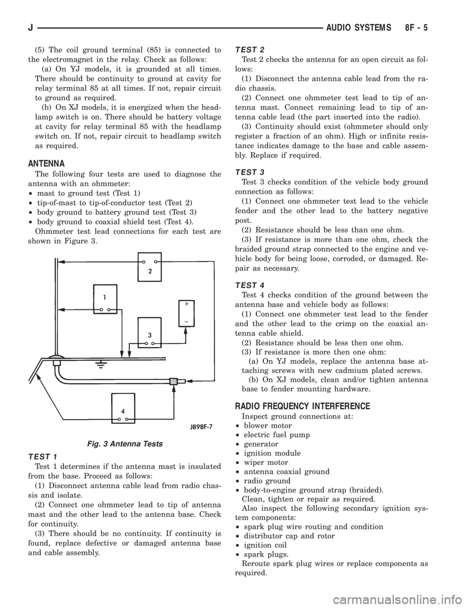
The following four tests are used to diagnose the
antenna with an ohmmeter:
²mast to ground test (Test 1)
²tip-of-mast to tip-of-conductor test (Test 2)
²body ground to battery ground test (Test 3)
²body ground to coaxial shield test (Test 4).
Ohmmeter test lead connections for each test are
shown in Figure 3.
TEST 1
Test 1 determines if the antenna mast is insulated
from the base. Proceed as follows:
(1) Disconnect antenna cable lead from radio chas-
sis and isolate.
(2) Connect one ohmmeter lead to tip of antenna
mast and the other lead to the antenna base. Check
for continuity.
(3) There should be no continuity. If continuity is
found, replace defective or damaged antenna base
and cable assembly.
TEST 2
Test 2 checks the antenna for an open circuit as fol-
lows:
(1) Disconnect the antenna cable lead from the ra-
dio chassis.
(2) Connect one ohmmeter test lead to tip of an-
tenna mast. Connect remaining lead to tip of an-
tenna cable lead (the part inserted into the radio).
(3) Continuity should exist (ohmmeter should only
register a fraction of an ohm). High or infinite resis-
tance indicates damage to the base and cable assem-
bly. Replace if required.
TEST 3
Test 3 checks condition of the vehicle body ground
connection as follows:
(1) Connect one ohmmeter test lead to the vehicle
fender and the other lead to the battery negative
post.
(2) Resistance should be less than one ohm.
(3) If resistance is more than one ohm, check the
braided ground strap connected to the engine and ve-
hicle body for being loose, corroded, or damaged. Re-
pair as necessary.
TEST 4
Test 4 checks condition of the ground between the
antenna base and vehicle body as follows:
(1) Connect one ohmmeter test lead to the fender
and the other lead to the crimp on the coaxial an-
tenna cable shield.
(2) Resistance should be less then one ohm.
(3) If resistance is more then one ohm:
(a) On YJ models, replace the antenna base at-
taching screws with new cadmium plated screws.
(b) On XJ models, clean and/or tighten antenna
base to fender mounting hardware.
RADIO FREQUENCY INTERFERENCE
Inspect ground connections at:
²blower motor
²electric fuel pump
²generator
²ignition module
²wiper motor
²antenna coaxial ground
²radio ground
²body-to-engine ground strap (braided).
Clean, tighten or repair as required.
Also inspect the following secondary ignition sys-
tem components:
²spark plug wire routing and condition
²distributor cap and rotor
²ignition coil
²spark plugs.
Reroute spark plug wires or replace components as
required.
Fig. 3 Antenna Tests
JAUDIO SYSTEMS 8F - 5
Page 411 of 2158

HORNS
CONTENTS
page page
DIAGNOSIS............................. 2
GENERAL INFORMATION.................. 1SERVICE PROCEDURES................... 3
SPECIFICATIONS......................... 5
GENERAL INFORMATION
Following are general descriptions of the major
components in the XJ (Cherokee)/YJ (Wrangler) horn
systems. Refer to Group 8W - Wiring Diagrams for
complete circuit descriptions and diagrams.
HORN SWITCH
XJ
Two horn switches are installed in the steering
wheel, one on each side of the center-mounted driv-
er's airbag module. When either switch is depressed
it completes a circuit to ground for the coil side of the
horn relay. The steering wheel and steering column
must be properly grounded for the horn switches to
function. The horn switches are only serviced as a set
with their wiring. If either switch should fail, both
switches must be replaced.
YJ
A single switch is installed in the center of the
steering wheel, directly under the horn button. When
the horn button is depressed the switch completes a
circuit to ground for the coil side of the horn relay.
The steering wheel and steering column must be
properly grounded for the horn switch to function.
The horn switch is available for service.
HORN RELAY
On XJ models, the horn relay is a mini-relay in-
stalled in the relay center, which is mounted to the
lower instrument panel reinforcement inboard of thesteering column. On YJ models, the horn relay is a
ISO relay installed in the Power Distribution Center
(PDC) near the battery tray. Refer to underside of
PDC cover for relay identification.
One side of the horn relay electromagnetic coil re-
ceives battery voltage at all times. When a horn
switch is depressed, the other side of the relay coil is
grounded. The energized relay coil causes the nor-
mally open relay contacts to close, providing battery
voltage to the horn.
If a problem is encountered with a continuously
sounding horn, it can usually be quickly resolved by
removing the horn relay until further diagnosis is
completed.
HORNS
On YJ models, a standard single, low-note, dia-
phragm-type horn is mounted and grounded to the
left inner fender shield under the hood. Dual horns
are standard equipment on XJ models. The high-note
diaphragm-type horn is mounted and grounded to
the left radiator closure panel brace behind the front
bumper. The low-note diaphragm-type horn is con-
nected in parallel with the high-note horn and is
mounted and grounded to the right radiator closure
panel brace behind the front bumper.
On XJ models, a cadmium-plated screw is
used to attach the horns to the body. Do not
substitute other types of screws as they may be-
come corroded and cause a loss of ground.
JHORNS 8G - 1