adding oil JEEP YJ 1995 Service And Repair Manual
[x] Cancel search | Manufacturer: JEEP, Model Year: 1995, Model line: YJ, Model: JEEP YJ 1995Pages: 2158, PDF Size: 81.9 MB
Page 34 of 2158
ENGINE MAINTENANCE
INDEX
page page
Accessory Drive Belt....................... 21
Air Cleaner Element....................... 18
Air-Conditioner Compressor.................. 21
Battery................................. 20
Crankcase Ventilation System................ 19
Emission Control System................... 20
Engine Break-In.......................... 15
Engine Cooling System..................... 18
Engine Oil.............................. 15Engine Oil Change and Filter Replacement...... 16
Engine Oil Filter.......................... 17
Engine Supports.......................... 21
Exhaust System.......................... 21
Fuel Filter............................... 19
Fuel Usage StatementÐGas Engines.......... 19
Ignition Cables, Distributor Cap and Rotor....... 20
Rubber and Plastic Component Inspection....... 20
Spark Plugs............................. 20
ENGINE BREAK-IN
CAUTION: Wide open throttle operation in low
gears, before engine break-in period is complete,
can damage engine.
After first starting a new engine, allow it to idle for
15 seconds before shifting into a drive gear. Also:
²Drive the vehicle at varying speeds less than 88
km/h (55 mph) for the first 480 km (300 miles).
²Avoid fast acceleration and sudden stops.
²Do not drive at full-throttle for extended periods of
time.
²Do not drive at constant speeds.
²Do not idle the engine excessively.
A special break-in engine oil is not required. The
original engine oil installed is a high quality, energy
conserving lubricant. Special break-in oils are not
recommended. These oils could interfere with the
normal piston ring seating process.
New engines tend to consume more fuel and oil un-
til after the break-in period has ended.
ENGINE OIL
WARNING: NEW OR USED ENGINE OIL CAN BE IR-
RITATING TO THE SKIN. AVOID PROLONGED OR
REPEATED SKIN CONTACT WITH ENGINE OIL.
CONTAMINANTS IN USED ENGINE OIL, CAUSED BY
INTERNAL COMBUSTION, CAN BE HAZARDOUS TO
YOUR HEALTH. THOROUGHLY WASH EXPOSED
SKIN WITH SOAP AND WATER.
DO NOT WASH SKIN WITH GASOLINE, DIESEL
FUEL, THINNER, OR SOLVENTS, HEALTH PROB-
LEMS CAN RESULT.
DO NOT POLLUTE, DISPOSE OF USED ENGINE
OIL PROPERLY. CONTACT YOUR DEALER OR GOV-
ERNMENT AGENCY FOR LOCATION OF COLLEC-
TION CENTER IN YOUR AREA.
ENGINE OIL SPECIFICATION
CAUTION: Do not use non-detergent or straight
mineral oil when adding or changing crankcase lu-
bricant. Engine failure can result.
API SERVICE GRADE CERTIFIED
Use an engine oil that is API Service Grade Certi-
fied or an oil that conforms to the API Service Grade
SH or SH/CD. MOPAR provides engine oils that con-
form to all of these service grades.
SAE VISCOSITY
An SAE viscosity grade is used to specify the vis-
cosity grade of engine oil. SAE 30 specifies a single
viscosity engine oil. Engine oils also have multiple
viscosities. These are specified with a dual SAE vis-
cosity grade which indicates the cold-to-hot tempera-
ture viscosity range. Select an engine oil that is best
suited to your particular temperature range and vari-
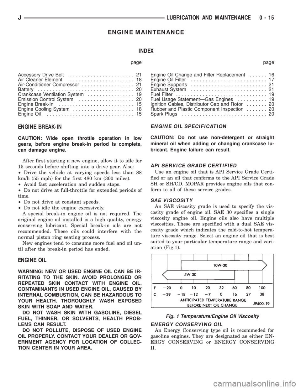
ation (Fig.1).
ENERGY CONSERVING OIL
An Energy Conserving type oil is recommeded for
gasoline engines. They are designated as either EN-
ERGY CONSERVING or ENERGY CONSERVING
II.
Fig. 1 Temperature/Engine Oil Viscosity
JLUBRICATION AND MAINTENANCE 0 - 15
Page 49 of 2158
FLUID LEVEL
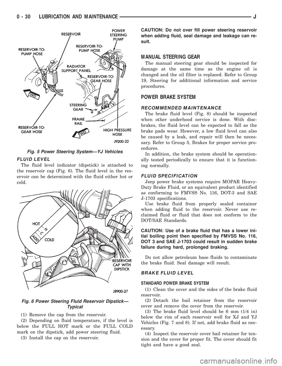
The fluid level indicator (dipstick) is attached to
the reservoir cap (Fig. 6). The fluid level in the res-
ervoir can be determined with the fluid either hot or
cold.
(1) Remove the cap from the reservoir.
(2) Depending on fluid temperature, if the level is
below the FULL HOT mark or the FULL COLD
mark on the dipstick, add power steering fluid.
(3) Install the cap on the reservoir.CAUTION: Do not over fill power steering reservoir
when adding fluid, seal damage and leakage can re-
sult.
MANUAL STEERING GEAR
The manual steering gear should be inspected for
damage at the same time as the engine oil is
changed and the oil filter is replaced. Refer to Group
19, Steering for additional information and service
procedures.
POWER BRAKE SYSTEM
RECOMMENDED MAINTENANCE
The brake fluid level (Fig. 8) should be inspected
when other underhood service is done. With disc-
brakes, the fluid level can be expected to fall as the
brake pads wear. However, a low fluid level can also
be caused by a leak, and repair will then be neces-
sary. Refer to Group 5, Brakes for proper service pro-
cedures.
In addition, the brake system should be operation-
ally tested periodically to ensure that it is function-
ing normally.
FLUID SPECIFICATION
Jeep power brake systems require MOPAR Heavy-
Duty Brake Fluid, or an equivalent product identified
as conforming to FMVSS No. 116, DOT-3 and SAE
J-1703 specifications.
Use brake fluid from properly sealed container
when adding fluid to the reservoir. Never use re-
claimed fluid or fluid that does not conform to the
DOT/SAE Standards.
CAUTION: Use of a brake fluid that has a lower ini-
tial boiling point then specified by FMVSS No. 116,
DOT 3 and SAE J-1703 could result in sudden brake
failure during hard, prolonged braking.
Do not allow petroleum base fluids to contaminate
the brake fluid. Seal damage will result.
BRAKE FLUID LEVEL
STANDARD POWER BRAKE SYSTEM
(1) Clean the cover and the sides of the brake fluid
reservoir.
(2) Detach the bail retainer from the reservoir
cover and remove the cover from the reservoir.
(3) The brake fluid level should be 6 mm (1/4 in)
below the rim of each reservoir well for XJ and YJ
Vehicles (Fig. 7 and 8). If not, add brake fluid as nec-
essary.
(4) Inspect the reservoir cover bail retainer for ten-
sion and the cover for proper fit. The cover should fit
tight and have a good seal.
Fig. 5 Power Steering SystemÐYJ Vehicles
Fig. 6 Power Steering Fluid Reservoir DipstickÐ
Typical
0 - 30 LUBRICATION AND MAINTENANCEJ
Page 159 of 2158
fied. This causes pull to switch direction in favor of
the brake unit that is functioning normally.
When diagnosing a change in pull condition, re-
member that pull will return to the original direction
if the dragging brake unit is allowed to cool down
(and is not seriously damaged).
REAR BRAKE GRAB
Rear grab (or pull) is usually caused by contami-
nated lining, bent or binding shoes and support
plates, or improperly assembled components. This is
particularly true when only one rear wheel is in-
volved. However, when both rear wheels are affected,
the master cylinder could be at fault.
BRAKES DO NOT HOLD AFTER DRIVING THROUGH
DEEP WATER PUDDLES
This condition is caused by water soaked lining. If
the lining is only wet, it can be dried by driving with
the brakes lightly applied for a mile or two. However,
if the lining is both wet and dirty, disassembly and
cleaning will be necessary.
CONTAMINATED BRAKELINING
Brakelining contaminated by water is salvageable.
The lining can either be air dried or dried using heat.
In cases where brakelining is contaminated by oil,
grease, or brake fluid, the lining should be replaced.
Replacement is especially necessary when fluids/lu-
bricants have actually soaked into the lining mate-
rial. However, grease or dirt that gets onto the lining
surface (from handling) during brake repairs, can be
cleaned off. Spray the lining surface clean with Mo-
par brake cleaner.
BRAKE FLUID CONTAMINATION
There are two basic causes of brake fluid contami-
nation. The first involves allowing dirt, debris, or
other materials to enter the cylinder reservoirs when
the cover is off. The second involves adding non-rec-
ommended fluids to the cylinder reservoirs.
Brake fluid contaminated with only dirt, or debris
usually retains a normal appearance. In some cases,
the foreign material will remain suspended in the
fluid and be visible. The fluid and foreign material
can be removed from the reservoir with a suction gun
but only if the brakes have not been applied. If the
brakes are applied after contamination, system flush-
ing will be required. The master cylinder may also
have to be disassembled, cleaned and the piston seals
replaced. Foreign material lodged in the reservoir
compensator/return ports can cause brake drag by re-
stricting fluid return after brake application.
Brake fluid contaminated by a non-recommended
fluid may appear discolored, milky, oily looking, or
foamy. However, remember that brake fluid will
darken in time and occasionally be cloudy in appear-ance. These are normal conditions and should not be
mistaken for contamination.
If some type of oil has been added to the system,
the fluid will separate into distinct layers. To verify
this, drain off a sample with a clean suction gun.
Then pour the sample into a glass container and ob-
serve fluid action. If the fluid separates into distinct
layers, it is definitely contaminated.
The only real correction for contamination by non-
recommended fluid is to flush the entire hydraulic
system and replace all the seals.
BRAKE NOISE
Squeak/Squeal
Factory installed brakelining is made from as-
bestos free materials. These materials have dif-
ferent operating characteristics than previous
lining material. Under certain conditions, as-
bestos free lining may generate some squeak,
groan or chirp noise. This noise is considered
normal and does not indicate a problem. The
only time inspection is necessary, is when noise
becomes constant or when grinding, scraping
noises occur.
Constant brake squeak or squeal may be due to lin-
ings that are wet or contaminated with brake fluid,
grease, or oil. Glazed linings, rotors/drums with hard
spots, and dirt/foreign material embedded in the
brake lining also cause squeak. Loud squeak, squeal,
scraping, or grinding sounds are a sign of severely
worn brake lining. If the lining has worn completely
through in spots, metal-to-metal contact occurs.
Thump/Clunk
Thumping or clunk noises during braking are fre-
quentlynotcaused by brake components. In many
cases, such noises are caused by loose or damaged
steering, suspension, or engine components. However,
calipers that bind on the slide surfaces can generate
a thump or clunk noise. In addition, worn out, im-
properly adjusted, or improperly assembled rear
brakeshoes can also produce a thump noise.
Chatter/Shudder
Brake chatter, or shudder is usually caused by
loose or worn components, or glazed/burnt lining. Ro-
tors with hard spots can also contribute to chatter.
Additional causes of chatter are out of tolerance ro-
tors, brake lining not securely attached to the shoes,
loose wheel bearings and contaminated brake lining.
WHEEL AND TIRE PROBLEMS
Some conditions attributed to brake components
may actually be caused by a wheel or tire problem.
A damaged wheel can cause shudder, vibration and
pull. A worn or damaged tire can also cause pull.
Severely worn tires with very little tread left can
JSERVICE BRAKE DIAGNOSIS 5 - 7
Page 162 of 2158
BRAKE FLUIDÐBRAKE BLEEDINGÐBRAKELINES AND HOSES
INDEX
page page
Brake Bleeding (With ABS Brakes)............ 11
Brake Bleeding (With Standard Brakes)......... 11
Brake Bleeding Recommendations............ 10
Brake Fluid Contamination.................. 10Brake Fluid Level......................... 10
Brakeline Charts.......................... 12
Brakelines and Hoses...................... 12
Recommended Brake Fluid.................. 10
RECOMMENDED BRAKE FLUID
Recommended brake fluid for Jeep vehicles is Mo-
par brake fluid, or an equivalent fluid meeting SAE
J1703 and DOT 3 standards. The recommendation
applies to models with standard or ABS brakes.
Use new brake fluid to top off the master cyl-
inder or refill the system. Never use reclaimed
fluid, fluid not meeting the SAE/DOT standards
or fluid from an unsealed container. Do not use
fluid from any container that has been left
open for any length of time. Fluid in open con-
tainers can absorb moisture.
BRAKE FLUID LEVEL
Always clean the master cylinder reservoir and
cover or cap before adding fluid. This avoids having
dirt from the cap or reservoir exterior fall into the
fluid.
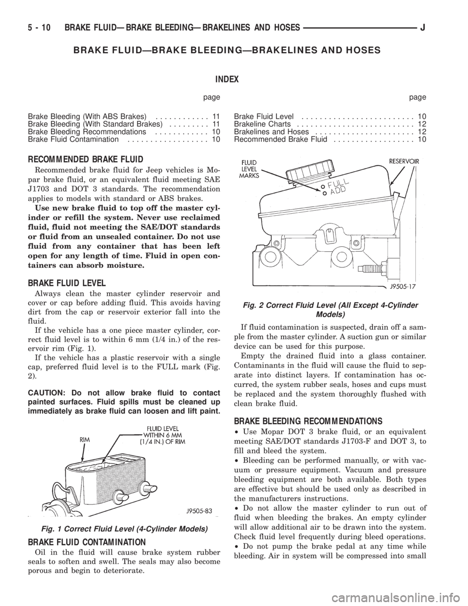
If the vehicle has a one piece master cylinder, cor-
rect fluid level is to within 6 mm (1/4 in.) of the res-
ervoir rim (Fig. 1).
If the vehicle has a plastic reservoir with a single
cap, preferred fluid level is to the FULL mark (Fig.
2).
CAUTION: Do not allow brake fluid to contact
painted surfaces. Fluid spills must be cleaned up
immediately as brake fluid can loosen and lift paint.
BRAKE FLUID CONTAMINATION
Oil in the fluid will cause brake system rubber
seals to soften and swell. The seals may also become
porous and begin to deteriorate.If fluid contamination is suspected, drain off a sam-
ple from the master cylinder. A suction gun or similar
device can be used for this purpose.
Empty the drained fluid into a glass container.
Contaminants in the fluid will cause the fluid to sep-
arate into distinct layers. If contamination has oc-
curred, the system rubber seals, hoses and cups must
be replaced and the system thoroughly flushed with
clean brake fluid.
BRAKE BLEEDING RECOMMENDATIONS
²Use Mopar DOT 3 brake fluid, or an equivalent
meeting SAE/DOT standards J1703-F and DOT 3, to
fill and bleed the system.
²Bleeding can be performed manually, or with vac-
uum or pressure equipment. Vacuum and pressure
bleeding equipment are both available. Both types
are effective but should be used only as described in
the manufacturers instructions.
²Do not allow the master cylinder to run out of
fluid when bleeding the brakes. An empty cylinder
will allow additional air to be drawn into the system.
Check fluid level frequently during bleed operations.
²Do not pump the brake pedal at any time while
bleeding. Air in system will be compressed into small
Fig. 1 Correct Fluid Level (4-Cylinder Models)
Fig. 2 Correct Fluid Level (All Except 4-Cylinder
Models)
5 - 10 BRAKE FLUIDÐBRAKE BLEEDINGÐBRAKELINES AND HOSESJ
Page 2087 of 2158
EVAPORATOR COIL:The coil is located in the
A/C housing. Its function is to remove heat and de-
humidify the air before it enters the vehicle.
FIN SENSING CYCLING CLUTCH SWITCH:
The switch is attached to the evaporator coil with the
temperature sensing probe inserted into the coil fins.
This switch controls evaporator temperature and pre-
vents condensate water on the evaporator coil from
freezing. It does this by sending signals to the Pow-
ertrain Control Module (PCM) to cycling the com-
pressor clutch on and off. This switch is used onXJ
only.
FILTER-DRIER:The drier is used to remove any
traces of moisture from the refrigerant system. A
sight glass is located on top of the filter drier. It is
used as a diagnostic tool to observe refrigerant flow.
HIGH PRESSURE RELIEF VALVE:The valve is
located on the filter drier. The valve is used to pre-
vent excessive high pressure build of 3445 to 4135
kPa (500 to 600 psi) and above. This prevents dam-
age to the compressor and other system components.
LOW-PRESSURE HIGH-PRESSURE CUT-OFF
SWITCH:The switch is located on the filter drier
and is wired in series with compressor clutch. When
the pressure drops down to 193 kPa (28 psi) the
switch interrupts the power to the compressor clutch.
When the pressure increases above 3100 to 3375 kPa
(450 to 490 psi) the switch interrupts the power to
the compressor clutch.
THERMOSTAT:The thermostat is located in the
evaporator housing. The thermostat temperature
sensing probe is inserted into the evaporator coil. Its
function is to cycles the compressor clutch on and off.
This switch controls temperature and prevents con-
densate water on the evaporator coil from freezing.
The thermostat is used on theYJonly.
REFRIGERANT LINES:The lines are used to
carry the refrigerant between the various system
components.
SERVICE PORTS:The high pressure service port
is located on the discharge line near the compressor.
The low pressure service port is located on the suc-
tion line near the compressor. These ports are used
to attach A/C gauges. After servicing the refrigerant
system, always install service port caps.
REFRIGERANT
XJ and YJ vehicles use a new type of refrigerant
called R-134a. It is a non-toxic, non-flammable, clear
color-less liquified gas.
R-134a refrigerant is not compatible with R-12 re-
frigerant. A small amount of R-12 in a R-134a system
will cause compressor failure, oil sludge or poor air
conditioning performance.R-134a refrigerant requires a special type of com-
pressor oil (SP20 PAG). When adding oil, make sure
that it is designed to be used in a R-134a system and
the SD7H15 compressor.
Service ports have been designed to ensure that
the system is not accidentally filled with R-12 refrig-
erant.
REFRIGERANT EQUIPMENT
WARNING: EYE PROTECTION MUST BE USED
WHEN SERVICING AN AIR CONDITIONING REFRIG-
ERANT SYSTEM. TURN OFF (ROTATE CLOCKWISE)
ALL VALVES ON THE EQUIPMENT BEING USED
BEFORE PROCEEDING WITH THIS OPERATION.
PERSONNEL INJURY CAN RESULT.
Chrysler Corporation recommends a (R-134a) recy-
cling device that meets SAE standard J2210 be used
when servicing the refrigerant system. Contact an
automotive service equipment supplier for refrigerant
recycling equipment that is available in your area.
Refer to the operating instructions provided with the
recycling equipment for proper operation.
MANIFOLD GAUGE SET
CAUTION: DO NOT use an R-12 manifold gauge set
on an R-134a system. The refrigerants are not com-
patible and system damage will result.
A manifold gauge set (Fig. 1) may be needed in
conjunction with the charging and or recovery/recy-
cling device. The service hoses on the gauge set being
used should have manual (turn wheel) or automatic
back flow valves at the service port connector ends.
This will prevent refrigerant from being release into
the atmosphere.
LOW PRESSURE GAUGE HOSE
The low pressure hose (BLUE with BLACK STRIP)
should be attached to the charging/service port. This
port is located at the right front of the engine com-
partment in the condenser-to-evaporator line.
HIGH PRESSURE GAUGE HOSE
The high pressure hose (RED with BLACK STRIP)
should be attached to the discharge/service port. This
port is located on the compressor plumbing or mani-
fold.
RECOVERY/RECYCLING/EVACUATION/
CHARGING HOSE
The center manifold hose (YELLOW or WHITE
with BLACK STRIP) is used to recover, evacuate and
charge the refrigerant system. When the low or high
pressure valves on the manifold gauge set are
opened, the refrigerant in the system will escape
through this hose.
JHEATING AND AIR CONDITIONING 24 - 7