brake rotor JEEP YJ 1995 Service And Repair Manual
[x] Cancel search | Manufacturer: JEEP, Model Year: 1995, Model line: YJ, Model: JEEP YJ 1995Pages: 2158, PDF Size: 81.9 MB
Page 24 of 2158
37,500 MILES (60 000 KM) OR AT 30 MONTHS
²Change engine oil.
²Replace engine oil filter.
²Lubricate steering linkage (4x4).
²Drain and refill manual transmission.
45,000 MILES (72 500 KM) OR AT 36 MONTHS
²Change engine oil.
²Replace engine oil filter.
²Lubricate steering linkage.
²Inspect brake linings.
²Flush and replace engine coolant, regardless of
mileage.
52,500 MILES (84 500 KM) OR AT 42 MONTHS
²Change engine oil.
²Replace engine oil filter.
²Lubricate steering linkage (4x4).
²Flush and replace engine coolant if not done at 36
months.
60,000 MILES (96 500 KM) OR AT 48 MONTHS
²Replace air cleaner element.
²Replace distributor cap and rotor.
²Replace ignition wires.
²Replace spark plugs.
²Adjust or replace drive belts.
²Change engine oil.
²Replace engine oil filter.
²Replace fuel filter. (See Note #1)
²Lubricate steering linkage.
²Drain and refill automatic transmission.
²Drain and refill transfer case.
67,500 MILES (108 500 KM) OR AT 54
MONTHS
²Change engine oil.
²Replace engine oil filter.
²Lubricate steering linkage (4x4).
²Inspect brake linings.
75,000 MILES (120 500 KM) OR AT 60
MONTHS
²Change engine oil.
²Replace engine oil filter.
²Lubricate steering linkage.
²Drain and refill manual transmission.
²Flush and replace engine coolant if it has been
30,000 miles (48 000 km) or 24 months since last
change.
82,500 MILES (133 000 KM) OR AT 66
MONTHS
²Change engine oil.
²Replace engine oil filter.
²Lubricate steering linkage (4x4).²Flush and replace engine coolant if it has been
30,000 miles (48 000 km) or 24 months since last
change.
90,000 MILES (145 000 KM) OR AT 72
MONTHS
²Replace air cleaner element.
²Replace spark plugs.
²Adjust drive belts.
²Change engine oil.
²Replace engine oil filter.
²Lubricate steering linkage.
²Inspect brake linings.
²Drain and refill automatic transmission.
²Drain and refill transfer case.
97,500 MILES (157 000 KM) OR AT 78
MONTHS
²Change engine oil.
²Replace engine oil filter.
²Lubricate steering linkage (4x4).
105,000 MILES (169 000 KM) OR AT 84
MONTHS
²Change engine oil.
²Replace engine oil filter.
²Lubricate steering linkage.
²Flush and replace engine coolant if it has been
30,000 miles (48 000 km) or 24 months since last
change.
112,500 MILES (181 000 KM) OR AT 90
MONTHS
²Change engine oil.
²Replace engine oil filter.
²Lubricate steering linkage (4x4).
²Inspect brake linings.
²Drain and refill manual transmission.
²Flush and replace engine coolant if it has been
30,000 miles (48 000 km) or 24 months since last
change.
120,000 MILES (193 000 KM) OR AT 96
MONTHS
²Replace air cleaner element.
²Replace distributor cap and rotor.
²Lubricate steering linkage.
²Drain and refill automatic transmission.
²Drain and refill transfer case.
²Replace ignition wires.
²Replace spark plugs.
²Adjust or replace drive belts.
²Change engine oil.
²Replace engine oil filter.
²Replace fuel filter. (See note #1)
JLUBRICATION AND MAINTENANCE 0 - 5
Page 26 of 2158
²Drain and refill automatic transmission fluid.
²Change front and rear axle fluid.*
²Replace air cleaner element.
²Replace distributor cap and rotor.
²Replace ignition wires.
²Adjust or replace drive belts.
²Replace fuel filter. See note #1.
²Inspect brake linings.
²Drain and refill transfer case.
63,000 MILES (102 000KM)
²Change engine oil.
²Replace engine oil filter.
66,000 MILES (105 600KM)
²Change engine oil.
²Replace engine oil filter.
²Lubricate steering linkage (4x4).
69,000 MILES (110 000KM)
²Change engine oil.
²Replace engine oil filter.
72,000 MILES (115 200KM)
²Change engine oil.
²Replace engine oil filter.
²Lubricate steering linkage (4x4).
²Drain and refill Manual transmission fluid.
²Drain and refill automatic transmission.
²Change front and rear axle fluid.*
²Inspect brake linings.
75,000 MILES (120 000KM)
²Change engine oil.
²Replace engine oil filter.
²Lubricate steering linkage (4x2).
²Inspect air cleaner element, replace as necessary.
78,000 MILES (125 000KM)
²Change engine oil.
²Replace engine oil filter.
²Lubricate steering linkage (4x4).
81,000 MILES (130 000KM)
²Change engine oil.
²Replace engine oil filter.
²Flush and replace engine coolant.
84,000 MILES (134 400KM)
²Change engine oil.
²Replace engine oil filter.
²Lubricate steering linkage (4x4).
²Drain and refill automatic transmission fluid.
²Change front and rear axle fluid.*
²Inspect brake linings.
87,000 MILES (140 000KM)
²Change engine oil.
²Replace engine oil filter.
90,000 MILES (144 000KM)
²Change engine oil.
²Replace engine oil filter.
²Lubricate steering linkage.
²Replace spark plugs.
²Drain and refill Manual transmission fluid.
²Replace air cleaner element.
²Adjust drive belts.
²Drain and refill transfer case fluid.
93,000 MILES (149 000KM)
²Change engine oil.
²Replace engine oil filter.
96,000 MILES (154 000KM)
²Change engine oil.
²Replace engine oil filter.
²Lubricate steering linkage (4x4).
²Drain and refill automatic transmission fluid.
²Change front and rear axle fluid.*
²Inspect brake linings.
99,000 MILES (158 400KM)
²Change engine oil.
²Replace engine oil filter.
102,000 MILES (163 000KM)
²Change engine oil.
²Replace engine oil filter.
²Lubricate steering linkage (4x4).
105,000 MILES (168 000KM)
²Change engine oil.
²Replace engine oil filter.
²Inspect air cleaner element, replace as necessary.
²Lubricate steering linkage (4x2).
108,000 MILES (172 800KM)
²Change engine oil.
²Replace engine oil filter.
²Lubricate steering linkage (4x4).
²Drain and refill Manual transmission fluid.
²Drain and refill automatic transmission fluid.
²Change front and rear axle fluid.*
²Inspect brake linings.
111,000 MILES (177 600KM)
²Change engine oil.
²Replace engine oil filter.
²Flush and replace engine coolant.
114,000 MILES (182 400KM)
²Change engine oil.
²Replace engine oil filter.
²Lubricate steering linkage (4x4).
117,000 MILES (187 200KM)
²Change engine oil.
²Replace engine oil filter.
JLUBRICATION AND MAINTENANCE 0 - 7
Page 27 of 2158
120,000 MILES (192 000KM)
²Change engine oil.
²Replace engine oil filter.
²Lubricate steering linkage.
²Replace spark plugs.
²Drain and refill automatic transmission fluid.
²Change front and rear axle fluid.*
²Inspect brake linings.
²Replace air cleaner element.
²Replace distributor cap and rotor.
²Replace ignition wires.
²Adjust or replace drive belts.
²Replace fuel filter. See note #1.²Drain and refill transfer case fluid.
NOTE 1:Not required for California vehicles, rec-
ommended for proper vehicle performance.
* Off-highway operation, trailer towing, taxi, limou-
sine, bus, snow plowing, or other types of commercial
service or prolonged operation with heavy loading,
especially in hot weather, require front and rear axle
service indicated witha*inScheduleÐB. Perform
these services if you usually operate your vehicle un-
der these conditions.
Inspection and service should also be performed
anytime a malfunction is observed or suspected.
0 - 8 LUBRICATION AND MAINTENANCEJ
Page 47 of 2158
CHASSIS AND BODY COMPONENTS
INDEX
page page
Body Components........................ 32
Chassis Component and Wheel Bearing
Lubricants............................. 28
Front Wheel Bearings...................... 28
Headlamps.............................. 33
Manual Steering Gear...................... 30Power Brake System....................... 30
Power Steering System..................... 29
Speedometer Cable....................... 33
Steering Linkage.......................... 28
Tires................................... 32
CHASSIS COMPONENT AND WHEEL BEARING
LUBRICANTS
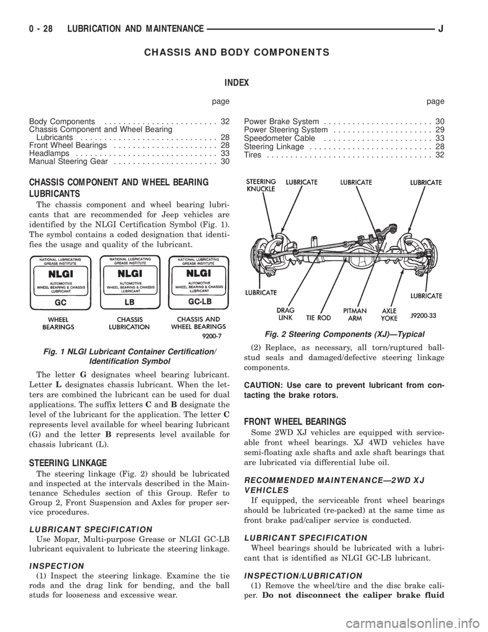
The chassis component and wheel bearing lubri-
cants that are recommended for Jeep vehicles are
identified by the NLGI Certification Symbol (Fig. 1).
The symbol contains a coded designation that identi-
fies the usage and quality of the lubricant.
The letterGdesignates wheel bearing lubricant.
LetterLdesignates chassis lubricant. When the let-
ters are combined the lubricant can be used for dual
applications. The suffix lettersCandBdesignate the
level of the lubricant for the application. The letterC
represents level available for wheel bearing lubricant
(G) and the letterBrepresents level available for
chassis lubricant (L).
STEERING LINKAGE
The steering linkage (Fig. 2) should be lubricated
and inspected at the intervals described in the Main-
tenance Schedules section of this Group. Refer to
Group 2, Front Suspension and Axles for proper ser-
vice procedures.
LUBRICANT SPECIFICATION
Use Mopar, Multi-purpose Grease or NLGI GC-LB
lubricant equivalent to lubricate the steering linkage.
INSPECTION
(1) Inspect the steering linkage. Examine the tie
rods and the drag link for bending, and the ball
studs for looseness and excessive wear.(2) Replace, as necessary, all torn/ruptured ball-
stud seals and damaged/defective steering linkage
components.
CAUTION: Use care to prevent lubricant from con-
tacting the brake rotors.
FRONT WHEEL BEARINGS
Some 2WD XJ vehicles are equipped with service-
able front wheel bearings. XJ 4WD vehicles have
semi-floating axle shafts and axle shaft bearings that
are lubricated via differential lube oil.
RECOMMENDED MAINTENANCEÐ2WD XJ
VEHICLES
If equipped, the serviceable front wheel bearings
should be lubricated (re-packed) at the same time as
front brake pad/caliper service is conducted.
LUBRICANT SPECIFICATION
Wheel bearings should be lubricated with a lubri-
cant that is identified as NLGI GC-LB lubricant.
INSPECTION/LUBRICATION
(1) Remove the wheel/tire and the disc brake cali-
per.Do not disconnect the caliper brake fluid
Fig. 1 NLGI Lubricant Container Certification/
Identification Symbol
Fig. 2 Steering Components (XJ)ÐTypical
0 - 28 LUBRICATION AND MAINTENANCEJ
Page 48 of 2158
hose unless the caliper must also be removed
for maintenance.Support the caliper with a
hanger to prevent brake fluid hose damage.
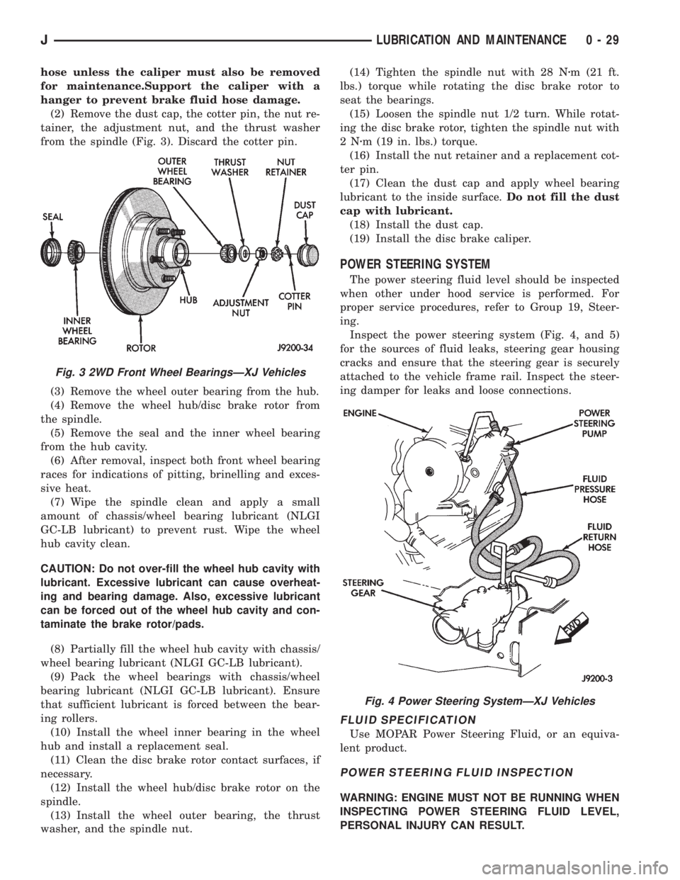
(2) Remove the dust cap, the cotter pin, the nut re-
tainer, the adjustment nut, and the thrust washer
from the spindle (Fig. 3). Discard the cotter pin.
(3) Remove the wheel outer bearing from the hub.
(4) Remove the wheel hub/disc brake rotor from
the spindle.
(5) Remove the seal and the inner wheel bearing
from the hub cavity.
(6) After removal, inspect both front wheel bearing
races for indications of pitting, brinelling and exces-
sive heat.
(7) Wipe the spindle clean and apply a small
amount of chassis/wheel bearing lubricant (NLGI
GC-LB lubricant) to prevent rust. Wipe the wheel
hub cavity clean.
CAUTION: Do not over-fill the wheel hub cavity with
lubricant. Excessive lubricant can cause overheat-
ing and bearing damage. Also, excessive lubricant
can be forced out of the wheel hub cavity and con-
taminate the brake rotor/pads.
(8) Partially fill the wheel hub cavity with chassis/
wheel bearing lubricant (NLGI GC-LB lubricant).
(9) Pack the wheel bearings with chassis/wheel
bearing lubricant (NLGI GC-LB lubricant). Ensure
that sufficient lubricant is forced between the bear-
ing rollers.
(10) Install the wheel inner bearing in the wheel
hub and install a replacement seal.
(11) Clean the disc brake rotor contact surfaces, if
necessary.
(12) Install the wheel hub/disc brake rotor on the
spindle.
(13) Install the wheel outer bearing, the thrust
washer, and the spindle nut.(14) Tighten the spindle nut with 28 Nzm (21 ft.
lbs.) torque while rotating the disc brake rotor to
seat the bearings.
(15) Loosen the spindle nut 1/2 turn. While rotat-
ing the disc brake rotor, tighten the spindle nut with
2Nzm (19 in. lbs.) torque.
(16) Install the nut retainer and a replacement cot-
ter pin.
(17) Clean the dust cap and apply wheel bearing
lubricant to the inside surface.Do not fill the dust
cap with lubricant.
(18) Install the dust cap.
(19) Install the disc brake caliper.
POWER STEERING SYSTEM
The power steering fluid level should be inspected
when other under hood service is performed. For
proper service procedures, refer to Group 19, Steer-
ing.
Inspect the power steering system (Fig. 4, and 5)
for the sources of fluid leaks, steering gear housing
cracks and ensure that the steering gear is securely
attached to the vehicle frame rail. Inspect the steer-
ing damper for leaks and loose connections.
FLUID SPECIFICATION
Use MOPAR Power Steering Fluid, or an equiva-
lent product.
POWER STEERING FLUID INSPECTION
WARNING: ENGINE MUST NOT BE RUNNING WHEN
INSPECTING POWER STEERING FLUID LEVEL,
PERSONAL INJURY CAN RESULT.
Fig. 3 2WD Front Wheel BearingsÐXJ Vehicles
Fig. 4 Power Steering SystemÐXJ Vehicles
JLUBRICATION AND MAINTENANCE 0 - 29
Page 51 of 2158
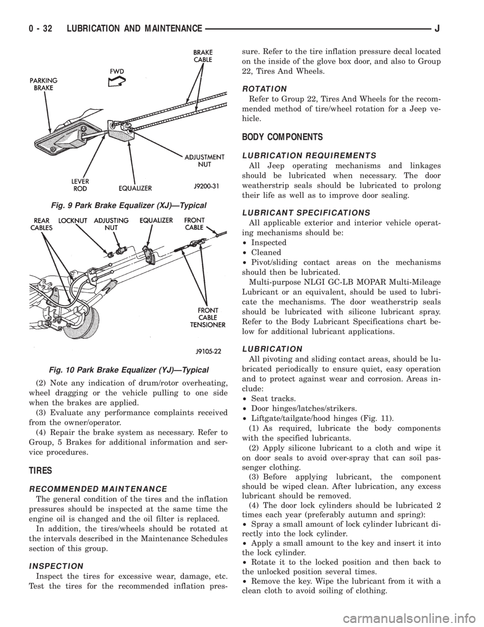
(2) Note any indication of drum/rotor overheating,
wheel dragging or the vehicle pulling to one side
when the brakes are applied.
(3) Evaluate any performance complaints received
from the owner/operator.
(4) Repair the brake system as necessary. Refer to
Group, 5 Brakes for additional information and ser-
vice procedures.
TIRES
RECOMMENDED MAINTENANCE
The general condition of the tires and the inflation
pressures should be inspected at the same time the
engine oil is changed and the oil filter is replaced.
In addition, the tires/wheels should be rotated at
the intervals described in the Maintenance Schedules
section of this group.
INSPECTION
Inspect the tires for excessive wear, damage, etc.
Test the tires for the recommended inflation pres-sure. Refer to the tire inflation pressure decal located
on the inside of the glove box door, and also to Group
22, Tires And Wheels.
ROTATION
Refer to Group 22, Tires And Wheels for the recom-
mended method of tire/wheel rotation for a Jeep ve-
hicle.
BODY COMPONENTS
LUBRICATION REQUIREMENTS
All Jeep operating mechanisms and linkages
should be lubricated when necessary. The door
weatherstrip seals should be lubricated to prolong
their life as well as to improve door sealing.
LUBRICANT SPECIFICATIONS
All applicable exterior and interior vehicle operat-
ing mechanisms should be:
²Inspected
²Cleaned
²Pivot/sliding contact areas on the mechanisms
should then be lubricated.
Multi-purpose NLGI GC-LB MOPAR Multi-Mileage
Lubricant or an equivalent, should be used to lubri-
cate the mechanisms. The door weatherstrip seals
should be lubricated with silicone lubricant spray.
Refer to the Body Lubricant Specifications chart be-
low for additional lubricant applications.
LUBRICATION
All pivoting and sliding contact areas, should be lu-
bricated periodically to ensure quiet, easy operation
and to protect against wear and corrosion. Areas in-
clude:
²Seat tracks.
²Door hinges/latches/strikers.
²Liftgate/tailgate/hood hinges (Fig. 11).
(1) As required, lubricate the body components
with the specified lubricants.
(2) Apply silicone lubricant to a cloth and wipe it
on door seals to avoid over-spray that can soil pas-
senger clothing.
(3) Before applying lubricant, the component
should be wiped clean. After lubrication, any excess
lubricant should be removed.
(4) The door lock cylinders should be lubricated 2
times each year (preferably autumn and spring):
²Spray a small amount of lock cylinder lubricant di-
rectly into the lock cylinder.
²Apply a small amount to the key and insert it into
the lock cylinder.
²Rotate it to the locked position and then back to
the unlocked position several times.
²Remove the key. Wipe the lubricant from it with a
clean cloth to avoid soiling of clothing.
Fig. 9 Park Brake Equalizer (XJ)ÐTypical
Fig. 10 Park Brake Equalizer (YJ)ÐTypical
0 - 32 LUBRICATION AND MAINTENANCEJ
Page 77 of 2158
(17) Tighten the track bar nut at the axle bracket
to 100 Nzm (74 ft. lbs.) torque.
(18) Check the front wheel alignment.
PINION SEAL REPLACEMENT
REMOVAL
(1) Raise and support the vehicle.
(2) Remove wheel and tire assemblies.
(3) Mark the propeller shaft yoke and pinion yoke
for installation alignment reference.
(4) Remove the propeller shaft from the yoke.
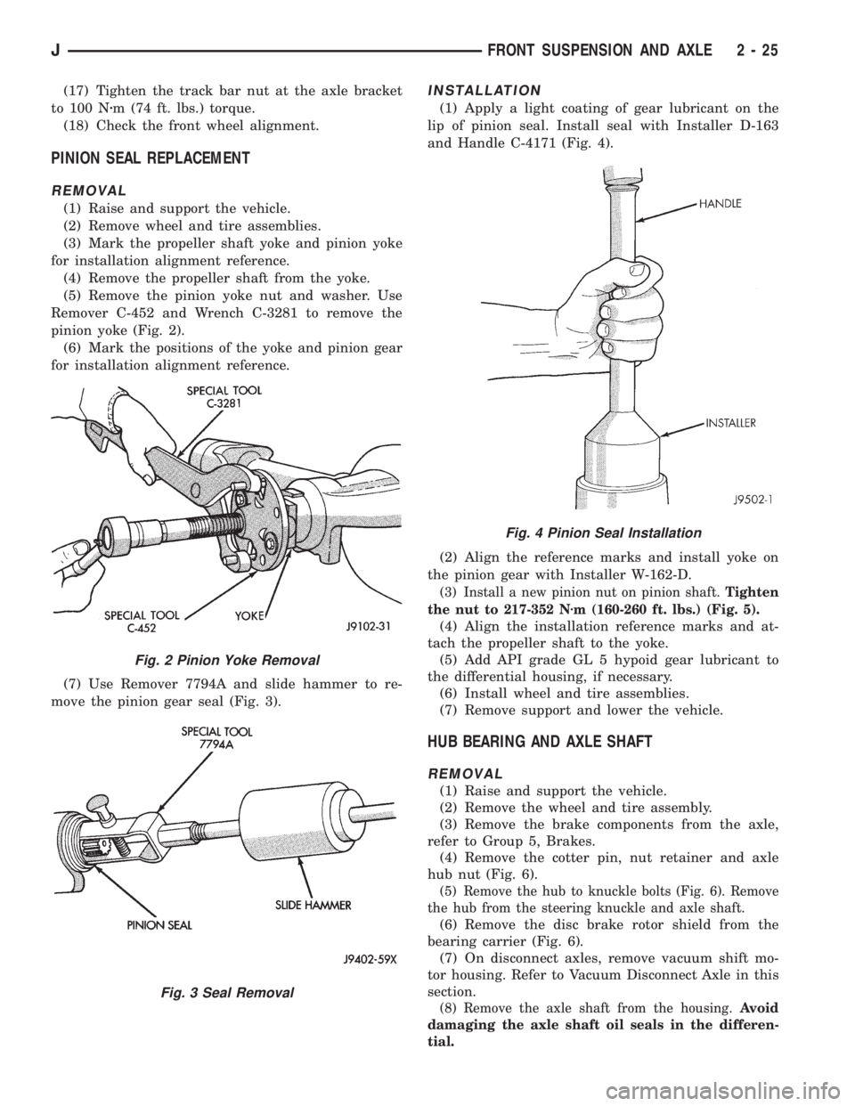
(5) Remove the pinion yoke nut and washer. Use
Remover C-452 and Wrench C-3281 to remove the
pinion yoke (Fig. 2).
(6) Mark the positions of the yoke and pinion gear
for installation alignment reference.
(7) Use Remover 7794A and slide hammer to re-
move the pinion gear seal (Fig. 3).
INSTALLATION
(1) Apply a light coating of gear lubricant on the
lip of pinion seal. Install seal with Installer D-163
and Handle C-4171 (Fig. 4).
(2) Align the reference marks and install yoke on
the pinion gear with Installer W-162-D.
(3) Install a new pinion nut on pinion shaft.Tighten
the nut to 217-352 Nzm (160-260 ft. lbs.) (Fig. 5).
(4) Align the installation reference marks and at-
tach the propeller shaft to the yoke.
(5) Add API grade GL 5 hypoid gear lubricant to
the differential housing, if necessary.
(6) Install wheel and tire assemblies.
(7) Remove support and lower the vehicle.
HUB BEARING AND AXLE SHAFT
REMOVAL
(1) Raise and support the vehicle.
(2) Remove the wheel and tire assembly.
(3) Remove the brake components from the axle,
refer to Group 5, Brakes.
(4) Remove the cotter pin, nut retainer and axle
hub nut (Fig. 6).
(5) Remove the hub to knuckle bolts (Fig. 6). Remove
the hub from the steering knuckle and axle shaft.
(6) Remove the disc brake rotor shield from the
bearing carrier (Fig. 6).
(7) On disconnect axles, remove vacuum shift mo-
tor housing. Refer to Vacuum Disconnect Axle in this
section.
(8) Remove the axle shaft from the housing.Avoid
damaging the axle shaft oil seals in the differen-
tial.
Fig. 2 Pinion Yoke Removal
Fig. 3 Seal Removal
Fig. 4 Pinion Seal Installation
JFRONT SUSPENSION AND AXLE 2 - 25
Page 153 of 2158
BRAKES
CONTENTS
page page
ABS BRAKE DIAGNOSIS................... 3
ABS OPERATION AND SERVICE............ 33
BRAKE FLUIDÐBRAKE BLEEDINGÐ
BRAKELINES AND HOSES............... 10
DISC BRAKES.......................... 45
DRUM BRAKES......................... 55
GENERAL INFORMATION.................. 1MASTER CYLINDERÐCOMBINATION VALVE . . 15
PARKING BRAKES....................... 60
POWER BRAKE BOOSTERÐBRAKE PEDALÐ
BRAKELIGHT SWITCH.................. 22
SERVICE BRAKE DIAGNOSIS............... 4
SPECIFICATIONS........................ 70
GENERAL INFORMATION
INDEX
page page
Antilock Brakes (ABS)....................... 1
Brake Components......................... 1
Brake Fluid/Lubricants/Cleaning Solvents......... 2
Brake Safety Precautions.................... 2Brake Warning Lights....................... 1
Brakelining Material........................ 1
Jeep Body Code Letters..................... 2
BRAKE COMPONENTS
Power assist front disc and rear drum brakes are
standard on Cherokee/Wrangler models. Disc brake
components consist of single piston calipers and ven-
tilated rotors. Rear drum brakes are dual shoe units
with cast brake drums.
The parking brake mechanism is lever and cable
operated. The cables are attached to levers on the
rear drum brake secondary shoes. The parking
brakes are operated by a foot pedal on YJ models and
a hand lever on XJ models.
A 205 mm dual diaphragm vacuum power brake
booster is used for all applications. Two master cylin-
ders are used; 4-cylinder YJ models have a one-piece
master cylinder. All other models have a two-piece
master cylinder with plastic reservoir.
All models are equipped with a combination valve.
The valve contains a pressure differential valve and
switch and a fixed rate rear proportioning valve.
BRAKELINING MATERIAL
Factory brakelining on all models consists of an or-
ganic base material combined with metallic particles.
The lining does not contain asbestos.
BRAKE WARNING LIGHTS
Cherokee/Wrangler models are equipped with one
or two brake warning lights. A red warning light is
standard on all models. An amber light is added on
models with ABS brakes. Both lights are located in
the instrument panel.
The red light is in circuit with the pressure differ-
ential switch (in the combination valve), and with the
parking brake switch. The light alerts the driver
when the parking brakes are applied, or when a
pressure differential exists between the front and
rear hydraulic systems. The light also illuminates for
a few seconds at start up as part of a bulb check.
The ABS warning light is amber in color and is lo-
cated in the same side of the instrument cluster as
the red warning light. The amber light only illumi-
nates when an ABS circuit fault occurs.
ANTILOCK BRAKES (ABS)
An antilock brake system (ABS) is available on
Cherokee/Wrangler models as an option. The system
is an electronically operated, all-wheel brake control
system. The ABS system is designed to prevent
wheel lockup during periods of high wheel slip brak-
ing. Refer to the antilock brake section for operation
and service information.
JBRAKES 5 - 1
Page 157 of 2158
hand lever. Also note if vehicle was being operated
with parking brake partially applied (this will cause
red light to remain on).
(7) Check brake pedal operation. Verify that pedal
does not bind and has adequate free play. If pedal
lacks free play, check pedal and power booster for be-
ing loose or for bind condition. Do not road test until
condition is corrected.
(8) If components inspected look OK, road test ve-
hicle.
ROAD TESTING
(1) If amber warning light is on, problem is with
antilock system component. Refer to antilock diagno-
sis section.
(2) If red warning light is not on, proceed to step
(4).
(3) If red warning light is on, proceed as follows:
(a) See if parking brakes are applied. If brakes
are applied, release them and proceed to step (4).
(b) Note if brake pedal is abnormally low. If
pedal is definitely low and red light is still on,
check front/rear hydraulic circuits for leak.Do not
road test. Inspect and repair as needed.
(4) Check brake pedal response with transmission
in Neutral and engine running. Pedal should remain
firm under steady foot pressure. If pedal falls away,
do not road test as problem is in master cylinder, or
HCU on ABS models. If pedal holds firm, proceed to
next step.
(5) During road test, make normal and firm brake
stops in 25-35 mph range. Note faulty brake opera-
tion such as hard pedal, pull, grab, drag, noise, fade,
etc.
(6) Return to shop and inspect brake components.
Refer to inspection and diagnosis information.
COMPONENT INSPECTION
Fluid leak points and dragging brake units can
usually be located without removing any components.
The area around a leak point will be wet with fluid.
The components at a dragging brake unit (wheel,
tire, rotor) will be quite warm or hot to the touch.
Other brake problem conditions will require compo-
nent removal for proper inspection. Raise the vehicle
and remove the necessary wheels for better visual ac-
cess.
During component inspection, pay particular atten-
tion to heavily rusted/corroded brake components
(e.g. rotors, caliper pistons, brake return/holddown
springs, support plates, etc.).
Heavy accumulations of rust may be covering se-
vere damage to a brake component. It is wise to re-
move surface rust in order to accurately determine
the depth of rust penetration and damage. Light sur-
face rust is fairly normal and not a major concern (as
long as it is removed). However, heavy rust buildup,especially on high mileage vehicles may cover struc-
tural damage to such important components as
brakelines, rotors, support plates, and brake boost-
ers. Refer to the wheel brake service procedures in
this group for more information.
BRAKE WARNING LIGHT OPERATION
The red brake warning light will illuminate under
the following conditions:
²for 2-3 seconds at startup as part of normal bulb
check
²when parking brakes are applied
²low pedal caused by leak in front/rear brake hy-
draulic circuit
If the red light remains on after startup, first ver-
ify that the parking brakes are fully released. Then
check pedal action and fluid level. A red light plus
low pedal indicates the pressure differential switch
and valve have been actuated due to a system leak.
On models with ABS brakes, the amber warning
light only illuminates when an ABS malfunction has
occurred. The ABS light operates independently of
the red warning light.
PEDAL FALLS AWAY
A brake pedal that falls away under steady foot
pressure is generally the result of a system leak. The
leak point could be at a brakeline, fitting, hose,
wheel cylinder, or caliper. Internal leakage in the
master cylinder caused by worn or damaged piston
cups, may also be the problem cause.
If leakage is severe, fluid will be evident at or
around the leaking component. However internal
leakage in the master cylinder will not be physically
evident. Refer to the cylinder test procedure at the
end of this section.
LOW PEDAL
If a low pedal is experienced, pump the pedal sev-
eral times. If the pedal comes back up, worn lining
and worn rotors or drums are the most likely causes.
However, if the pedal remains low and the red warn-
ing light is on, the likely cause is a leak in the hy-
draulic system.
A decrease in master cylinder fluid level may only
be the result of normal lining wear. Fluid level will
drop somewhat as lining wear occurs. It is a result of
the outward movement of caliper and wheel cylinder
pistons to compensate for normal wear.
SPONGY PEDAL
Air in the system is the usual cause of a spongy
pedal. Brake drums machined way beyond allowable
limits (too thin), or substandard brake lines and
hoses can also cause a condition similar to a spongy
JSERVICE BRAKE DIAGNOSIS 5 - 5
Page 158 of 2158
pedal. The proper course of action is to bleed the sys-
tem, or replace thin drums and suspect quality brake
lines and hoses.
HARD PEDAL OR HIGH PEDAL EFFORT
A hard pedal or high pedal effort may be due to lin-
ing that is water soaked, contaminated, glazed, or
badly worn. The power booster or check valve could
also be faulty. Test the booster and valve as described
in this section.
BRAKE DRAG
Brake drag occurs when the lining is in constant
contact with the rotor or drum. Drag can occur at one
wheel, all wheels, fronts only, or rears only. It is a
product of incomplete brakeshoe release. Drag can be
minor or severe enough to overheat the linings, ro-
tors and drums. A drag condition also worsens as
temperature of the brake parts increases.
Brake drag also has a direct effect on fuel economy.
If undetected, minor brake drag can be misdiagnosed
as an engine or transmission/torque converter prob-
lem.
Minor drag will usually cause slight surface char-
ring of the lining. It can also generate hard spots in
rotors and drums from the overheat/cool down pro-
cess. In most cases, the rotors, drums, wheels and
tires are quite warm to the touch after the vehicle is
stopped.
Severe drag can char the brake lining all the way
through. It can also distort and score rotors and
drums to the point of replacement. The wheels, tires
and brake components will be extremely hot. In se-
vere cases, the lining may generate smoke as it chars
from overheating.
An additional cause of drag involves the use of in-
correct length caliper mounting bolts. Bolts that are
too long can cause a partial apply condition. The cor-
rect caliper bolts have a shank length of 67 mm
(2.637 in.), plus or minus 0.6 mm (0.0236 in.). Refer
to the Disc Brake service section for more detail on
caliper bolt dimensions and identification.
Some common causes of brake drag are:
²loose or damaged wheel bearing
²seized or sticking caliper or wheel cylinder piston
²caliper binding on bolts or slide surfaces
²wrong length caliper mounting bolts (too long)
²loose caliper mounting bracket
²distorted rotor, brake drum, or shoes
²brakeshoes binding on worn/damaged support
plates
²severely rusted/corroded components
²misassembled components.
If brake drag occurs at all wheels, the problem may
be related to a blocked master cylinder compensatorport or faulty power booster (binds-does not release).
The condition will worsen as brake temperature in-
creases.
The brakelight switch can also be a cause of drag.
An improperly mounted or adjusted brakelight
switch can prevent full brake pedal return. The re-
sult will be the same as if the master cylinder com-
pensator ports are blocked. The brakes would be
partially applied causing drag.
BRAKE FADE
Brake fade is a product of overheating caused by
brake drag. However, overheating and subsequent
fade can also be caused by riding the brake pedal,
making repeated high deceleration stops in a short
time span, or constant braking on steep roads. Refer
to the Brake Drag information in this section for
causes.
PEDAL PULSATION (NON-ABS BRAKES ONLY)
Pedal pulsation is caused by parts that are loose,
or beyond tolerance limits. This type of pulsation is
constant and will occur every time the brakes are ap-
plied.
Disc brake rotors with excessive lateral runout or
thickness variation, or out of round brake drums are
the primary causes of pulsation.
On vehicles with ABS brakes, remember that pedal
pulsation is normal during antilock mode brake
stops. If pulsation occurs during light to moderate
brake stops, a standard brake part is either loose, or
worn beyond tolerance.
BRAKE PULL
A front pull condition could be the result of:
²contaminated lining in one caliper
²seized caliper piston
²binding caliper
²wrong caliper mounting bolts (too long)
²loose caliper
²loose or corroded mounting bolts
²improper brakeshoes
²damaged rotor
²incorrect wheel bearing adjustment (at one wheel)
A worn, damaged wheel bearing or suspension com-
ponent are further causes of pull. A damaged front
tire (bruised, ply separation) can also cause pull.
Wrong caliper bolts (too long) will cause a partial ap-
ply condition and pull if only one caliper is involved.
A common and frequently misdiagnosed pull condi-
tion is where direction of pull changes after a few
stops. The cause is a combination of brake drag fol-
lowed by fade at the dragging brake unit.
As the dragging brake overheats, efficiency is so re-
duced that fade occurs. If the opposite brake unit is
still functioning normally, its braking effect is magni-
5 - 6 SERVICE BRAKE DIAGNOSISJ