sensor KIA AMANTI 2006 User Guide
[x] Cancel search | Manufacturer: KIA, Model Year: 2006, Model line: AMANTI, Model: KIA AMANTI 2006Pages: 322, PDF Size: 44.16 MB
Page 88 of 322
377
1
2
3
4
5
6
7
8
910
Knowing your vehicle
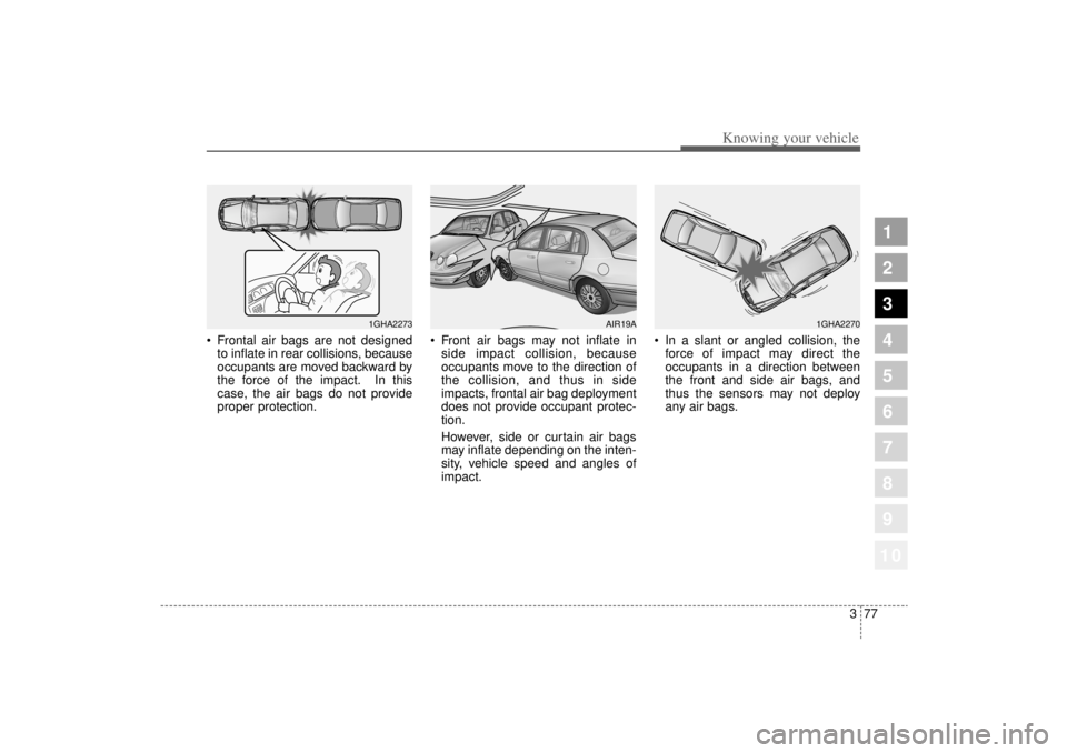
Frontal air bags are not designed
to inflate in rear collisions, because
occupants are moved backward by
the force of the impact. In this
case, the air bags do not provide
proper protection.
Front air bags may not inflate in
side impact collision, because
occupants move to the direction of
the collision, and thus in side
impacts, frontal air bag deployment
does not provide occupant protec-
tion.
However, side or curtain air bags
may inflate depending on the inten-
sity, vehicle speed and angles of
impact.
In a slant or angled collision, the
force of impact may direct the
occupants in a direction between
the front and side air bags, and
thus the sensors may not deploy
any air bags.
1GHA2273
AIR19A
1GHA2270
Page 89 of 322
Knowing your vehicle78
3
1
2
3
4
5
6
7
8
910
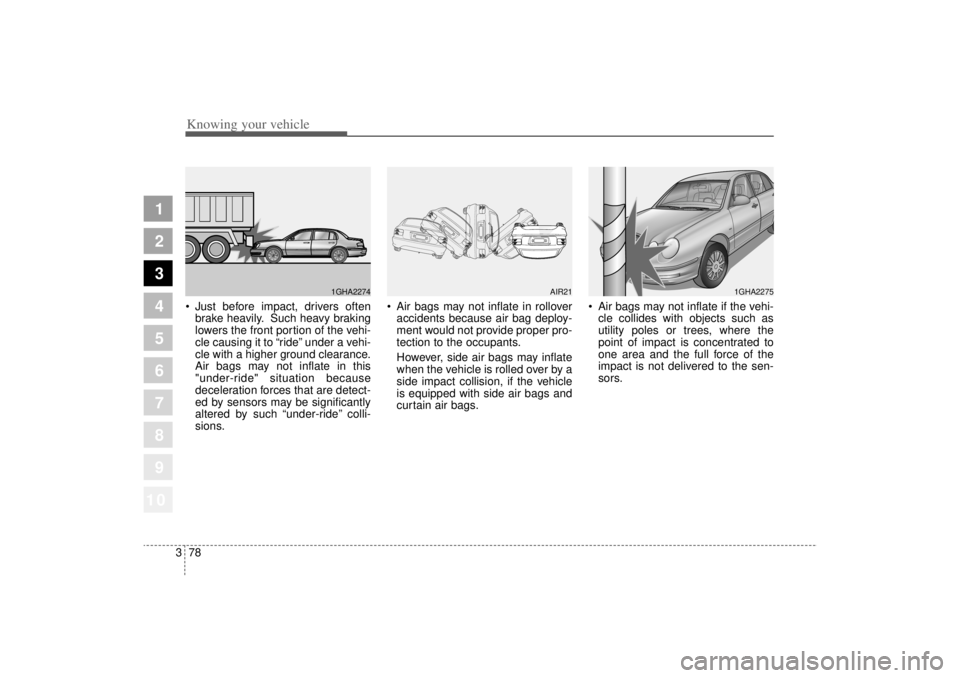
Just before impact, drivers often
brake heavily. Such heavy braking
lowers the front portion of the vehi-
cle causing it to “ride”under a vehi-
cle with a higher ground clearance.
Air bags may not inflate in this
"under-ride" situation because
deceleration forces that are detect-
ed by sensors may be significantly
altered by such “under-ride”colli-
sions.
Air bags may not inflate in rollover
accidents because air bag deploy-
ment would not provide proper pro-
tection to the occupants.
However, side air bags may inflate
when the vehicle is rolled over by a
side impact collision, if the vehicle
is equipped with side air bags and
curtain air bags.
Air bags may not inflate if the vehi-
cle collides with objects such as
utility poles or trees, where the
point of impact is concentrated to
one area and the full force of the
impact is not delivered to the sen-
sors.
1GHA2274
AIR21
1GHA2275
Page 90 of 322

379
1
2
3
4
5
6
7
8
910
Knowing your vehicle
How does the air bag system
operate Air bag only operates when the
ignition switch is turned to the ON
or START positions.
Air bags inflate instantly in the
event of serious frontal or side col-
lision (if equipped with side air bag
or curtain air bag) in order to help
protect the occupants from serious
physical injury.
There is no single speed at which
the air bags will inflate.
Generally, air bags are designed to
inflate by the severity of a collision
and its direction. These two factors
determine whether the sensors
send out an electronic deploy-
ment/inflation signal.
Air bag deployment depends on a
number of factors including vehicle
speed, angles of impact and the
density and stiffness of the vehi-
cles or objects which your vehicle
hits in the collision. However, fac-
tors are not limited to those men-
tioned above.
The front air bags will completely
inflate and deflate in an instant.
It is virtually impossible for you to
see the air bags inflate during an
accident. It is much more likely that
you will simply see the deflated air
bags hanging out of their storage
compartments after the collision.
In order to help provide protection
in a severe collision, the air bags
must inflate rapidly. The speed of
air bag inflation is a consequence
of the extremely short time in which
a collision occurs and the need to
get the air bag between the occu-
pant and the vehicle structures
before the occupant impacts those
structures. This speed of inflation
reduces the risk of serious or life-
threatening injuries in a severe col-
lision and is thus a necessary part
of air bag design.
However, air bag inflation can also
cause injuries which normally can
include facial abrasions, bruises
and broken bones, and sometimes
more serious injuries because that
inflation speed also causes the air
bags to expand with a great deal
force.
There are even circumstances
under which contact with the
steering wheel air bag can cause
fatal injuries, especially if the
occupant is positioned exces-
sively close to the steering
wheel.
Page 106 of 322
395
1
2
3
4
5
6
7
8
910
Knowing your vehicle
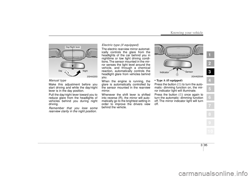
Manual type Make this adjustment before you
start driving and while the day/night
lever is in the day position.
Pull the day/night lever toward you to
reduce glare from the headlights of
vehicles behind you during night
driving.Remember that you lose somerearview clarity in the night position. Electric type (if equipped)
The electric rearview mirror automat-
ically controls the glare from the
headlights of the car behind you in
nighttime or low light driving condi-
tions. The sensor mounted in the mir-
ror senses the light level around the
vehicle, and through a chemical
reaction, automatically controls the
headlight glare from vehicles behind
you.
When the engine is running, the
glare is automatically controlled by
the sensor mounted in the rearview
mirror.
Whenever the shift lever is shifted
into reverse (R), the mirror will auto-
matically go to the brightest setting in
order to improve the drivers view
behind the vehicle.
• Type A (if equipped)
Press the button (
➀) to turn the auto-
matic- dimming function on, the mir-
ror indicator light will illuminate.
Press the button (➀) once again to
turn the automatic- dimming function
off. The mirror indicator light will turn
off.
2GHA2203
Day
Night
Day/Night lever
2GHA2204A
Sensor
➀
Indicator
Page 140 of 322
Driving your vehicle18
4
1
2
3
4
5
6
7
8
910
Power steeringPower Steering uses energy from the
engine to assist you in steering the
vehicle. If the engine is off or if the
power steering system becomes
inoperative, the vehicle may still be
steered, but it will require increased
steering effort.
Should you notice any change in the
effort required to steer during normal
vehicle operation, have the power
steering checked by an Authorized
Kia Dealer.
Electronic power steering The wheel speed sensor controls
steering power according to the vehi-
cle’s speed.
The steering wheel becomes heavier
as the vehicle’s speed increases and
becomes lighter as the vehicle’s
speed decreases for the better con-
trol of the steering wheel.
✽ ✽
NOTICE• Never hold the steering wheel
against a stop (extreme right or
left turn) for more than 5 seconds
with the engine running. Holding
the steering wheel for more than 5
seconds in either position may
cause damage to the power steer-
ing pump.
• If the power steering drive belt breaks or if the power steering
pump malfunctions, the steering
effort will greatly increase.
STEERING WHEEL
Page 151 of 322
429
1
2
3
4
5
6
7
8
910
Driving your vehicle
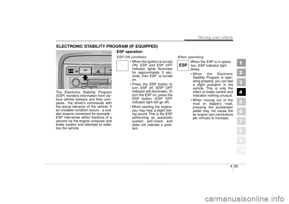
The Electronic Stability Program
(ESP) monitors information from var-
ious vehicle sensors and then com-
pares the driver's commands with
the actual behavior of the vehicle. If
an unstable condition occurs - a sud-
den evasive movement for example -
ESP intervenes within fractions of a
second via the engine computer and
brake system and attempts to stabi-
lize the vehicle.
ESP operationESP ON condition
When the ignition is turnedON, ESP and ESP OFF
indicator lights illuminate
for approximately 3 sec-
onds, then ESP is turned
on.
Press the ESP button to turn ESP off. (ESP OFF
indicator will illuminate). To
turn the ESP on, press the
ESP button (ESP OFF
indicator light will go off).
When starting the engine, you may hear a slight tick-
ing sound. This is the ESP
performing an automatic
system self-check and
does not indicate a prob-
lem.
When operating
When the ESP is in opera-
tion, ESP indicator light
blinks.
When the ElectronicStability Program is oper-
ating properly, you can feel
a slight pulsation in the
vehicle. This is only the
effect of brake control and
indicates nothing unusual.
When moving out of the mud or slippery road,
pressing the accelerator
pedal may not cause the
bv engine rpm (revolutions
per minute) to increase.
ELECTRONIC STABILITY PROGRAM (IF EQUIPPED)
-
ESP
ESP
2GHN2051D
Page 167 of 322
445
1
2
3
4
5
6
7
8
910
Driving your vehicle
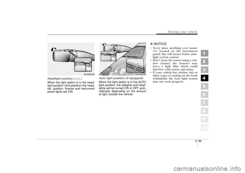
Headlight position ( )When the light switch is in the head-
light position (2nd position) the head,
tail, position, license and instrument
panel lights are ON.
Auto light position (if equipped)When the light switch is in the AUTO
light position, the taillights and head-
lights will be turned ON or OFF auto-
matically depending on the amount
of light outside the vehicle.
✽ ✽NOTICE• Never place anything over sensor
(
➀) located on the instrument
panel, this will ensure better auto-
light system control.
• Don’t clean the sensor using a win- dow cleaner, the cleanser may
leave a light film which could
interfere with sensor operation.
• If your vehicle has window tint or other types of coating on the front
windshield, the Auto light system
may not work properly.
1GHA2053A
1GHA2233A
Page 194 of 322
Driving tips25FUEL REQUIREMENTSGasoline engine (unleaded)Your new Kia vehicle is designed to
use only unleaded fuel with a mini-
mum Octane Rating of 87 Anti-
Knock Index (AKI).✽ ✽NOTICENEVER USE LEADED FUEL. The
use of leaded fuel is detrimental to
the catalytic converter and will
damage the engine control system’s
oxygen sensor and affect emission
control.
Never add any fuel system cleaning
agents to the fuel tank other than
what Kia has specified. (Consult an
Authorized Kia Dealer for details.)
Gasoline containing alcohol
and methanolGasohol, a mixture of gasoline and
ethanol (also known as grain alco-
hol), and gasoline or gasohol con-
taining methanol (also known as
wood alcohol) are being marketed
along with or instead of leaded or
unleaded gasoline.
Do not use gasohol containing more
than 10% ethanol, and do not use
gasoline or gasohol containing any
methanol. Either of these fuels may
cause drivability problems and dam-
age to the fuel system.
Discontinue using gasohol of any
kind if drivability problems occur. Vehicle damage or driveability prob-
lems may not be covered by the
manufacturer’s warranty if they result
from the use of:
1. Gasohol containing more than
10% ethanol.
2. Gasoline or gasohol containing methanol.
3. Leaded fuel or leaded gasohol.
✽ ✽ NOTICENever use gasohol which contains
methanol. Discontinue use of any
gasohol product which impairs dri-
vability.
1
2
3
4
5
6
7
8
910
Page 215 of 322
523
Driving tips
1
2
3
4
5
6
7
8
910
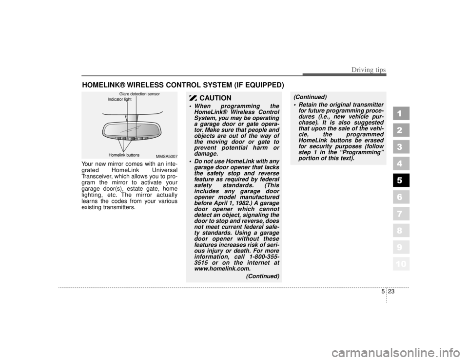
HOMELINK® WIRELESS CONTROL SYSTEM (IF EQUIPPED)Your new mirror comes with an inte-
grated HomeLink Universal
Transceiver, which allows you to pro-
gram the mirror to activate your
garage door(s), estate gate, home
lighting, etc. The mirror actually
learns the codes from your various
existing transmitters.
CAUTION
When programming theHomeLink® Wireless ControlSystem, you may be operatinga garage door or gate opera-tor. Make sure that people andobjects are out of the way ofthe moving door or gate toprevent potential harm ordamage.
Do not use HomeLink with any garage door opener that lacksthe safety stop and reversefeature as required by federalsafety standards. (Thisincludes any garage dooropener model manufacturedbefore April 1, 1982.) A garagedoor opener which cannotdetect an object, signaling thedoor to stop and reverse, doesnot meet current federal safe-ty standards. Using a garagedoor opener without thesefeatures increases risk of seri-ous injury or death. For moreinformation, call 1-800-355-3515 or on the internet atwww.homelink.com.
(Continued)
(Continued) Retain the original transmitter for future programming proce-dures (i.e., new vehicle pur-chase). It is also suggestedthat upon the sale of the vehi-cle, the programmedHomeLink buttons be erasedfor security purposes (followstep 1 in the “Programming”portion of this text).
MMSA5007
Homelink buttons Glare detection sensor
Indicator light
Page 232 of 322
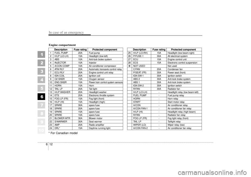
In case of an emergency12
6
1
2
3
4
5
6
7
8
910
* For Canadian model
Description Fuse rating Protected component
1 FUEL PUMP 20A Fuel pump
2 H/LP (LO-LH) 15A Headlight (low-left)
3 ABS 10A Anti-lock brake system
4 INJECTOR 10A Injector
5 A/CON COMP 10A Air-conditioner compressor
6 ATM RLY 20A Automatic transaxle control relay
7 ECU RLY 20A Engine control unit relay
8 IGN COIL 20A Ignition coil
9 O2 SNSR 15A Oxygen sensor
10 ENG SNSR 15A
Power train control system sensors
11 HORN 15A Horn
12 TAIL LP 20A Tail light
13 H/LP WASHER 20A Headlight washer
14 ETS 20A Electronic throttle system
15 FOG LP (FR) 15A Fog light (front)
16 H/LP (HI) 15A Headlight (high)
17 SPARE 30A spare fuse
18 SPARE 20A spare fuse
19 SPARE 15A spare fuse
20 SPARE 10A spare fuse
21 BLOWER MTR 30A Blower motor
22 S/WARMER 30A Seat warmer
23 AMP 20A Radio amplifier
24 DRL* 15A Daytime running light
Description Fuse rating Protected component
25 H/LP (LO-RH) 15A Headlight (low beam-right)
26 P/FUSE-1 30A All electrical system
27 ECU 10A Engine control unit
28 ECS 15A Electronic control suspension
� NOT USED Not used
C/FAN 20A Condenser fan
P/SEAT (FR) 30A Power seat (front)
IGN SW-1 30A Ignition switch
ABS 2 30A Anti-lock brake system
ABS 1 30A Anti-lock brake system
IGN SW-2 30A Ignition switch
R/FAN 30A Radiator fan
H/LP (LO-LH) - Headlight relay (low beam-left)
FUEL PUMP - Fuel pump relay
HORN - Horn relay
START - Start motor relay
A/CON - Air conditioner relay
A/CON FAN-1 - Air conditioner fan relay
H/LP (HI) - Headlight relay (high beam)
R/FAN - Radiator fan relay
FOG LP (FR) - Fog light relay (front)
TAIL LP - Taillight relay
WIPER (LO) - Wiper relay (low)
A/CON FAN-2 - Air conditioner fan relay
Engine compartment