KIA AMANTI 2009 Owners Manual
Manufacturer: KIA, Model Year: 2009, Model line: AMANTI, Model: KIA AMANTI 2009Pages: 321, PDF Size: 23.77 MB
Page 231 of 321
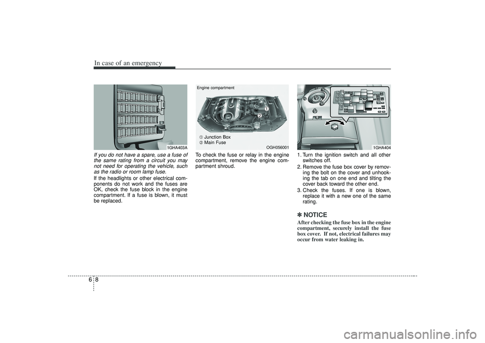
In case of an emergency86If you do not have a spare, use a fuse ofthe same rating from a circuit you maynot need for operating the vehicle, suchas the radio or room lamp fuse.If the headlights or other electrical com-
ponents do not work and the fuses are
OK, check the fuse block in the engine
compartment. If a fuse is blown, it must
be replaced. To check the fuse or relay in the engine
compartment, remove the engine com-
partment shroud.
1. Turn the ignition switch and all other
switches off.
2. Remove the fuse box cover by remov- ing the bolt on the cover and unhook-
ing the tab on one end and tilting the
cover back toward the other end.
3. Check the fuses. If one is blown, replace it with a new one of the same
rating.
✽ ✽NOTICEAfter checking the fuse box in the engine
compartment, securely install the fuse
box cover. If not, electrical failures may
occur from water leaking in.
1GHA403A
1GHA404
OGH056001
Engine compartment➀
➁
➀
Junction Box
➁ Main Fuse
Page 232 of 321
69
In case of an emergency
Main fuseIf the BATT (60A) or ALT (150A) fuse are
blown, it must be removed as follows:
1. Disconnect the negative battery cable.
2. Remove the nuts shown in the pictureabove.
3. Replace the fuse with a new one of the same rating.
4. Reinstall in the reverse order of removal.
OGH046004
Engine compartment
91950-3F100
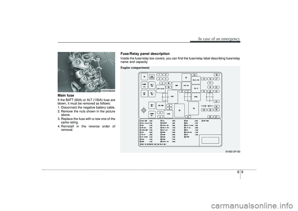
Fuse/Relay panel descriptionInside the fuse/relay box covers, you can find the fuse/relay label describing fuse/relay
name and capacity.
Page 233 of 321
In case of an emergency10
6
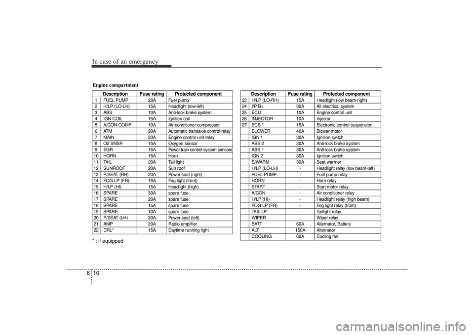
Description Fuse rating Protected component
1 FUEL PUMP 20A Fuel pump
2 H/LP (LO-LH) 15A Headlight (low-left)
3 ABS 10A Anti-lock brake system
4 IGN COIL 15A Ignition coil
5 A/CON COMP 10A Air-conditioner compressor
6 ATM 20A Automatic transaxle control relay
7 MAIN 20A Engine control unit relay
8 O2 SNSR 15A Oxygen sensor
9 EGR 15A
Power train control system sensors
10 HORN 15A Horn
11 TAIL 20A Tail light
12 SUNROOF 20A Sun roof
13 P/SEAT (RH) 20A Power seat (right)
14 FOG LP (FR) 15A Fog light (front)
15 H/LP (HI) 15A Headlight (high)
16 SPARE 30A spare fuse
17 SPARE 20A spare fuse
18 SPARE 15A spare fuse
19 SPARE 10A spare fuse
20 P/SEAT (LH) 30A Power seat (left)
21 AMP 20A Radio amplifier
22 DRL* 15A Daytime running lightEngine compartment
Description Fuse rating Protected component
23 H/LP (LO-RH) 15A Headlight (low beam-right)
24 I/P B+ 30A All electrical system
25 ECU 10A Engine control unit
26 INJECTOR 10A Injector
27 ECS * 15A Electronic control suspension
BLOWER 40A Blower motor
IGN 1 30A Ignition switch
ABS 2 30A Anti-lock brake system
ABS 1 30A Anti-lock brake system
IGN 2 30A Ignition switch
S/WARM 30A Seat warmer
H/LP (LO-LH) - Headlight relay (low beam-left)
FUEL PUMP - Fuel pump relay
HORN - Horn relay
START - Start motor relay
A/CON - Air conditioner relay
H/LP (HI) - Headlight relay (high beam)
FOG LP (FR) - Fog light relay (front)
TAIL LP - Taillight relay
WIPER - Wiper relay
BATT 60A Alternator, Battery
ALT 150A Alternator
COOLING 60A Cooling fan
* : if equipped
Page 234 of 321
611
In case of an emergency
Driver-side knee bolster
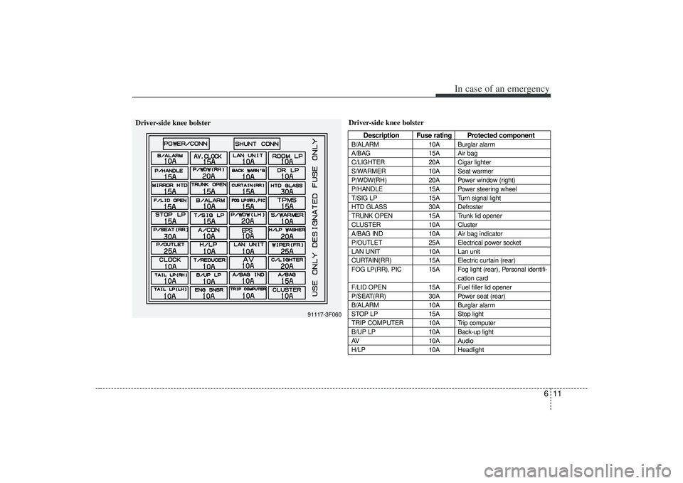
Description Fuse rating Protected component
B/ALARM10A Burglar alarm
A/BAG 15A Air bag
C/LIGHTER 20A Cigar lighter
S/WARMER 10A Seat warmer
P/WDW(RH) 20A Power window (right)
P/HANDLE 15A Power steering wheel
T/SIG LP 15A Turn signal light
HTD GLASS 30A Defroster
TRUNK OPEN 15A Trunk lid opener
CLUSTER 10A Cluster
A/BAG IND 10A Air bag indicator
P/OUTLET 25A Electrical power socket
LAN UNIT 10A Lan unit
CURTAIN(RR) 15A Electric curtain (rear)
FOG LP(RR), PIC 15A Fog light (rear), Personal identifi- cation card
F/LID OPEN 15A Fuel filler lid opener
P/SEAT(RR) 30A Power seat (rear)
B/ALARM 10A Burglar alarm
STOP LP 15A Stop light
TRIP COMPUTER 10A Trip computer
B/UP LP 10A Back-up light
AV 10A Audio
H/LP 10A Headlight
91117-3F060
Driver-side knee bolster
Page 235 of 321

In case of an emergency12
6
Power connectorYour vehicle is equipped with a power connector to prevent bat-
tery discharge if your vehicle is parked without being operated
for prolonged periods. Use the following procedures before
parking the vehicle for prolonged period.
1. Turn off the engine.
2. Turn off the headlights and tail lights.
3. Open the driver-side knee bolster cover and pull up the
“POWER/CONN”.✽ ✽NOTICE• If the power connector is pulled up from the fuse panel, the
warning chime, AV system, clock and intetrior lamps, etc.,
will not operate. Some items must be reset after replace-
ment.
• Even though the power connector is pulled up, the battery can still be discharged by operation of the headlights or
other electrical devices.
Description Fuse rating Protected component
A/CON 10A Air-conditioning system
P/WDW(LH) 20A Power window (left)
TAIL LP(RH) 10A Taillight (right)
BACK WARN’G 10A Back warning
DR LP 10A Door courtesy lamp
MIRROR HTD 15A Outside review mirror defroster
ENG SNSR 10A
Power train control system sensors
T/REDUCER10A Seat belt tension reducer
CLOCK 10A Clock
WIPER(FR) 25A Wiper (front)
EPS 10A Electronic power steering
TAIL LP(LH) 10A Tail light (left)
ROOM LP 10A Room lamp
AV, CLOCK 15A Audio, Clock
LAN UNIT 10A Lan unit
TPMS 15A Tire pressure monitoring system
H/LP WASHER 20A Headlight washer
SHUNT CONN - Switch illumination
POWER/CONN - Power connector
1GHA403
Power
connector
Page 236 of 321
613
In case of an emergency
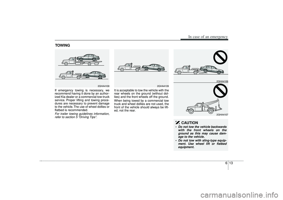
TOWING If emergency towing is necessary, we
recommend having it done by an author-
ized Kia dealer or a commercial tow-truck
service. Proper lifting and towing proce-
dures are necessary to prevent damage
to the vehicle. The use of wheel dollies or
flatbed is recommended.For trailer towing guidelines information,refer to section 5 “Driving Tips”.
It is acceptable to tow the vehicle with the
rear wheels on the ground (without dol-
lies) and the front wheels off the ground.
When being towed by a commercial tow
truck and wheel dollies are not used, the
front of the vehicle should always be lift-
ed, not the rear.
2GHA4107 2GHA4106
2GHA4108
2GHA4109
CAUTION
Do not tow the vehicle backwards with the front wheels on theground as this may cause dam- age to the vehicle.
Do not tow with sling-type equip- ment. Use wheel lift or flatbedequipment.
Page 237 of 321
In case of an emergency14
6When towing your vehicle in an emer-
gency without wheel dollies :
1. Set the ignition switch in the ACC posi-
tion.
2. Place the transaxle shift lever in N (Neutral).
3. Release the parking brake.
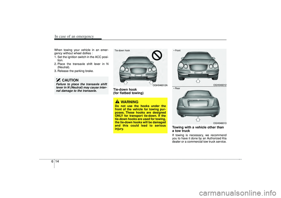
Tie-down hook
(for flatbed towing)
Towing with a vehicle other than
a tow truck
If towing is necessary, we recommend
you to have it done by an Authorized Kia
dealer or a commercial tow truck service.
OGH046012A
Tie-down hook
WARNING
Do not use the hooks under the
front of the vehicle for towing pur-
poses. These hooks are designed
ONLY for transport tie-down. If the
tie-down hooks are used for towing,
the tie-down hooks will be damaged
and this could lead to serious
injury.
CAUTION
Failure to place the transaxle shift
lever in N (Neutral) may cause inter-nal damage to the transaxle.
OGH046012
OGH046013
Page 238 of 321
615
In case of an emergency
If towing service is not available in an
emergency, your vehicle may be tem-
porarily towed using a cable or chain
secured to the emergency towing hook
under the front or rear of the vehicle. Use
extreme caution when towing the vehicle.
A driver must be in the vehicle to steer it
and operate the brakes.
Towing in this manner may be done only
on hard-surfaced roads for a short dis-
tance and at low speeds. Also, the
wheels, axles, power train, steering and
brakes must all be in good condition.
Do not use the tow hooks to pull avehicle out of mud, sand or other con-
ditions from which the vehicle cannot
be driven out under its own power.
Avoid towing a vehicle heavier than the vehicle doing the towing.
The drivers of both vehicles should communicate with each other frequent-
ly. Before emergency towing, check that
the hook is not broken or damaged.
Fasten the towing cable or chain securely to the hook.
Do not jerk the hook. Apply steady and even force.
To avoid damaging the hook, do not pull from the side or at a vertical angle.
Always pull straight ahead.
CAUTION
Attach a towing strap to the tow hook.
Using a portion of the vehicle other than the tow hooks for tow-ing may damage the body of yourvehicle.
Use only a cable or chain specifi- cally intended for use in towingvehicles. Securely fasten the cable or chain to the towing hookprovided.
WARNING
Use extreme caution when towing
the vehicle.
Avoid sudden starts or erratic driving maneuvers which would
place excessive stress on the
emergency towing hook and tow-
ing cable or chain. The hook and
towing cable or chain may break
and cause serious injury or dam-
age.
If the towing vehicle can hardly move, do not forcibly continue
the towing. Contact an Authorized
Kia dealer or a commercial tow
truck service for assistance.
Tow the vehicle as straight ahead as possible.
Keep away from the vehicle dur- ing towing.
Page 239 of 321
In case of an emergency16
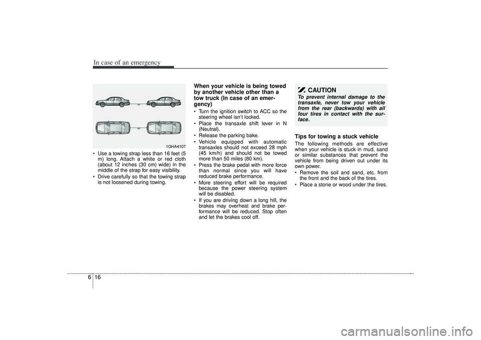
6 Use a towing strap less than 16 feet (5
m) long. Attach a white or red cloth
(about 12 inches (30 cm) wide) in the
middle of the strap for easy visibility.
Drive carefully so that the towing strap is not loosened during towing.
When your vehicle is being towed
by another vehicle other than a
tow truck (In case of an emer-
gency) Turn the ignition switch to ACC so thesteering wheel isn’t locked.
Place the transaxle shift lever in N (Neutral).
Release the parking bake.
Vehicle equipped with automatic transaxles should not exceed 28 mph
(45 km/h) and should not be towed
more than 50 miles (80 km).
Press the brake pedal with more force than normal since you will have
reduced brake performance.
More steering effort will be required because the power steering system
will be disabled.
If you are driving down a long hill, the brakes may overheat and brake per-
formance will be reduced. Stop often
and let the brakes cool off.
Tips for towing a stuck vehicleThe following methods are effective
when your vehicle is stuck in mud, sand
or similar substances that prevent the
vehicle from being driven out under its
own power.
Remove the soil and sand, etc. fromthe front and the back of the tires.
Place a stone or wood under the tires.
1GHA4107
CAUTION
To prevent internal damage to the transaxle, never tow your vehiclefrom the rear (backwards) with allfour tires in contact with the sur- face.
Page 240 of 321

617
In case of an emergency
TIRES PRESSURE MONITORING SYSTEM (TPMS) (IF EQUIPPED)
➀
Low Tire Pressure Telltale
➁
TPMS Malfunction Indicator
Each tire, including the spare (if pro-
vided), should be checked monthly
when cold and inflated to the inflation
pressure recommended by the vehi-
cle manufacturer on the vehicle plac-
ard or tire inflation pressure label. (If
your vehicle has tires of a different
size than the size indicated on the
vehicle placard or tire inflation pres-
sure label, you should determine the
proper tire inflation pressure for
those tires.) As an added safety feature, your
vehicle has been equipped with a tire
pressure monitoring system (TPMS)
that illuminates a low tire pressure
telltale when one or more of your
tires is significantly under-inflated.
Accordingly, when the low tire pres-
sure telltale illuminates, you should
stop and check your tires as soon as
possible, and inflate them to the
proper pressure. Driving on a signifi-
cantly under-inflated tire causes the
tire to overheat and can lead to tire
failure. Under-inflation also reduces
fuel efficiency and tire tread life, and
may affect the vehicle’s handling and
stopping ability.
Please note that the TPMS is not a
substitute for proper tire mainte-
nance, and it is the driver’s responsi-
bility to maintain correct tire pres-
sure, even if under-inflation has not
reached the level to trigger illumina-
tion of the TPMS low tire pressure
telltale.
Your vehicle has also been equipped
with a TPMS malfunction indicator to
indicate when the system is not
operating properly. The TPMS mal-
function indicator is provided by a
separate telltale, which displays the
symbol "TPMS" when illuminated.
When the malfunction indicator is
illuminated, the system may not be
able to detect or signal low tire pres-
sure as intended. TPMS malfunc-
tions may occur for a variety of rea-
sons, including the installation of
replacement or alternate tires or
wheels on the vehicle that prevent
the TPMS from functioning properly.
Always check the TPMS malfunction
telltale after replacing one or more
tires or wheels on your vehicle to
ensure that the replacement or alter-
nate tires and wheels allow the
TPMS to continue to function proper-
ly.
OGH049436N➀
➁