relay KIA Cadenza 2014 1.G Owner's Manual
[x] Cancel search | Manufacturer: KIA, Model Year: 2014, Model line: Cadenza, Model: KIA Cadenza 2014 1.GPages: 415, PDF Size: 5.09 MB
Page 105 of 415
437
Features of your vehicle
STEERING WHEEL
Electric power steering (EPS)
Power steering uses the motor to
assist you in steering the vehicle. If
the engine is off or if the power steer-
ing system becomes inoperative, the
vehicle may still be steered, but it will
require increased steering effort.
The motor driven power steering is
controlled by the power steering con-
trol unit which senses the steering
wheel torque and vehicle speed to
command the motor.
The steering wheel becomes heavier
as the vehicle’s speed increases and
becomes lighter as the vehicle’s
speed decreases for better control of
the steering wheel.
Should you notice any change in the
effort required to steer during normal
vehicle operation, have the power
steering checked by an authorized
Kia dealer.
✽ ✽NOTICE
The following symptoms may occur
during normal vehicle operation:
• The steering effort is increased
immediately after turning the igni-
tion switch on. This happens as the
system performs the EPS system
diagnostics. When the diagnostics
are completed, the steering wheel
will return to its normal condition
• A click noise may be heard from the EPS relay after the ignition
switch is turned to the ON or
LOCK position.
• Motor noise may be heard when the vehicle is at a stop or at a low
driving speed.
• The steering effort increases if the steering wheel is rotated continu-
ously when the vehicle is not in
motion. However, after a few min-
utes, it will return to its normal
conditions.
• When you operate the steering wheel in low temperature, abnor-
mal noise could occur. If tempera-
ture rises, the noise will disappear.
This is a normal condition.
If the Electric Power Steering System
does not operate normally, the warn-
ing light will illuminate on the instru-
ment cluster. The steering wheel may
become difficult to control or operate
abnormally. Take your vehicle to an
authorized Kia dealer and have the
vehicle checked as soon as possible.
Page 374 of 415
761
Maintenance
FUSES
A vehicle’s electrical system is pro-
tected from electrical overload dam-
age by fuses.
This vehicle has 2 fuse panels, one
located in the driver’s side panel bol-
ster, the other in the engine compart-
ment near the battery.
If any of your vehicle’s lights, acces-
sories, or controls do not work, check
the appropriate circuit fuse. If a fuse
has blown, the element inside the
fuse will melt.
If the electrical system does not
work, first check the driver’s side
fuse panel.
Before replacing a blown fuse, dis-
connect the negative battery cable.
Always replace a blown fuse with
one of the same rating.
If the replacement fuse blows, this
indicates an electrical problem. Avoid
using the system involved and imme-
diately consult an authorized Kia
dealer.
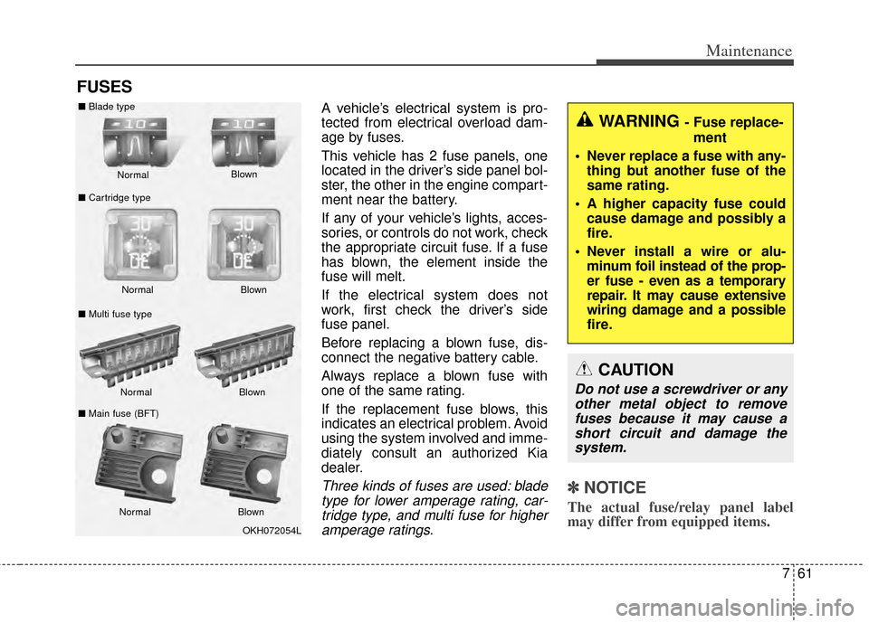
Three kinds of fuses are used: bladetype for lower amperage rating, car-tridge type, and multi fuse for higheramperage ratings.✽ ✽ NOTICE
The actual fuse/relay panel label
may differ from equipped items.
WARNING - Fuse replace-
ment
Never replace a fuse with any- thing but another fuse of the
same rating.
A higher capacity fuse could cause damage and possibly a
fire.
Never install a wire or alu- minum foil instead of the prop-
er fuse - even as a temporary
repair. It may cause extensive
wiring damage and a possible
fire.
CAUTION
Do not use a screwdriver or anyother metal object to removefuses because it may cause ashort circuit and damage thesystem.
OKH072054L
Normal
Normal
■
Blade type
■ Cartridge type
■ Multi fuse type Blown
Blown
Normal Blown
Normal Blown
■
Main fuse (BFT)
Page 375 of 415

Maintenance
62
7
Instrument panel fuse replace-
ment
1. Turn the ignition switch and all
other switches off.
2. Open the fuse panel cover. 3. Pull the suspected fuse straight
out. Use the fuse puller provided in
the engine compartment fuse
panel.
4. Check the removed fuse; replace it if it is blown.
5. Push in a new fuse of the same rating, and make sure it fits tightly
in the clips.
If it fits loosely, consult an authorized
Kia dealer.
If you do not have a spare, use a fuse of the same rating from a circuityou may not need for operating thevehicle, such as the cigarette lighterfuse.
CAUTION
When replacing a blown fuse or relay with a new one, makesure the new fuse or relay fitstightly into the clips Theincomplete fastening fuse orrelay may cause the vehiclewiring and electric systemsdamage and a possible fire.
Do not remove fuses, relays and terminals fastened withbolts or nuts. The fuses, relaysand terminals may be fas-tened incompletely, and it maycause a possible fire. If fuses,relays and terminals fastenedwith bolts or nuts are blown,we recommend that you con-sult with an authorized Kiadealer.
Do not input any other objects except fuses or relays intofuse/relay terminals such as adriver or wiring. It may causecontact failure and systemmalfunction.
OVG073018
OVG079019
Page 378 of 415

765
Maintenance
Instrument fuse panel
✽
✽NOTICE
Not all fuse panel descriptions in
this manual may be applicable to
your vehicle. It is accurate at the
time of printing. When you inspect
the fuse panel in your vehicle, refer
to the fuse panel label.
OVG073024
OVG073104N
Fuse/relay panel description
Inside the fuse/relay panel covers, you can find the fuse/relay label describing fuse/relay name and capacity.
Page 382 of 415
769
Maintenance
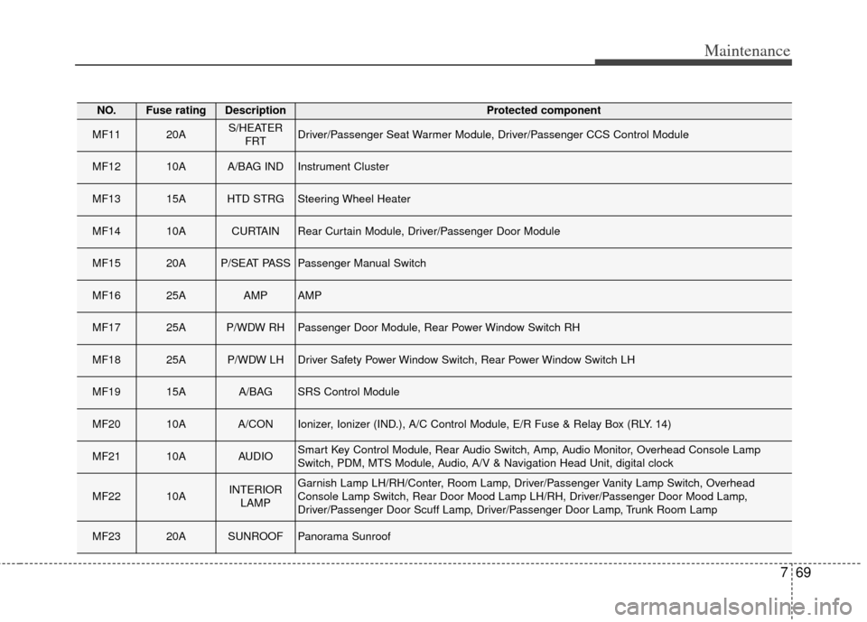
NO.Fuse ratingDescriptionProtected component
MF1120AS/HEATERFRTDriver/Passenger Seat Warmer Module, Driver/Passenger CCS Control Module
MF1210AA/BAG INDInstrument Cluster
MF1315AHTD STRGSteering Wheel Heater
MF1410ACURTAINRear Curtain Module, Driver/Passenger Door Module
MF1520AP/SEAT PASSPassenger Manual Switch
MF1625AAMPAMP
MF1725AP/WDW RHPassenger Door Module, Rear Power Window Switch RH
MF1825AP/WDW LHDriver Safety Power Window Switch, Rear Power Window Switch LH
MF1915AA/BAGSRS Control Module
MF2010AA/CONIonizer, Ionizer (IND.), A/C Control Module, E/R Fuse & Relay Box (RLY. 14)
MF2110AAUDIOSmart Key Control Module, Rear Audio Switch, Amp, Audio Monitor, Overhead Console Lamp
Switch, PDM, MTS Module, Audio, A/V & Navigation Head Unit, digital clock
MF2210AINTERIORLAMPGarnish Lamp LH/RH/Conter, Room Lamp, Driver/Passenger Vanity Lamp Switch, Overhead
Console Lamp Switch, Rear Door Mood Lamp LH/RH, Driver/Passenger Door Mood Lamp,
Driver/Passenger Door Scuff Lamp, Driver/Passenger Door Lamp, Trunk Room Lamp
MF2320ASUNROOFPanorama Sunroof
Page 383 of 415
Maintenance
70
7
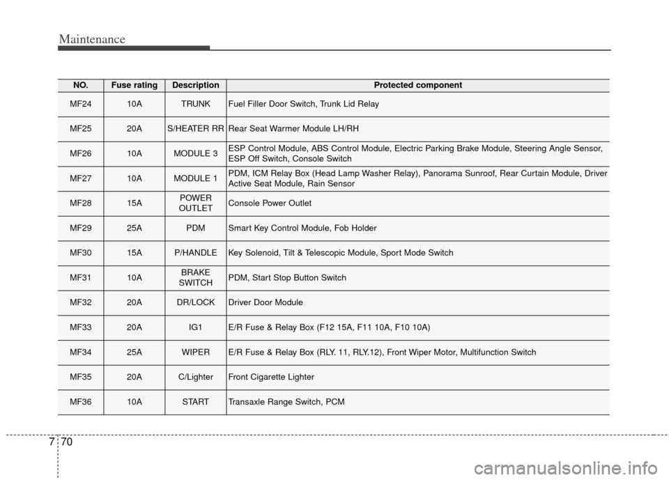
NO.Fuse ratingDescriptionProtected component
MF2410ATRUNKFuel Filler Door Switch, Trunk Lid Relay
MF2520AS/HEATER RRRear Seat Warmer Module LH/RH
MF2610AMODULE 3ESP Control Module, ABS Control Module, Electric Parking Brake Module, Steering Angle Sensor,
ESP Off Switch, Console Switch
MF2710AMODULE 1PDM, ICM Relay Box (Head Lamp Washer Relay), Panorama Sunroof, Rear Curtain Module, Driver
Active Seat Module, Rain Sensor
MF2815APOWER
OUTLETConsole Power Outlet
MF2925APDMSmart Key Control Module, Fob Holder
MF3015AP/HANDLEKey Solenoid, Tilt & Telescopic Module, Sport Mode Switch
MF3110ABRAKE
SWITCHPDM, Start Stop Button Switch
MF3220ADR/LOCKDriver Door Module
MF3320AIG1E/R Fuse & Relay Box (F12 15A, F11 10A, F10 10A)
MF3425AWIPERE/R Fuse & Relay Box (RLY. 11, RLY.12), Front Wiper Motor, Multifunction Switch
MF3520AC/LighterFront Cigarette Lighter
MF3610ASTARTTransaxle Range Switch, PCM
Page 384 of 415
771
Maintenance
NO.Fuse ratingDescriptionProtected component
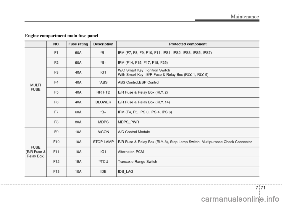
MULTIFUSE
F160A2B+IPM (F7, F8, F9, F10, F11, IPS1, IPS2, IPS3, IPS5, IPS7)
F260A3B+IPM (F14, F15, F17, F18, F25)
F340AIG1W/O Smart Key : Ignition Switch
With Smart Key : E/R Fuse & Relay Box (RLY. 1, RLY. 9)
F440A1ABSABS Control,ESP Control
F540ARR HTDE/R Fuse & Relay Box (RLY. 2)
F640ABLOWERE/R Fuse & Relay Box (RLY. 14)
F760A4B+IPM (F4, F5, IPS 0, IPS 4, IPS 6)
F880AMDPSMDPS_PWR
FUSE
(E/R Fuse & Relay Box)
F910AA/CONA/C Control Module
F1010ASTOP LAMPE/R Fuse & Relay Box (RLY. 8), Stop Lamp Switch, Multipurpose Check Connector
F1110AIG1Alternator, PCM
F1215AT2TCUTransaxle Range Switch
F1310AIDBIDB_LAG
Engine compartment main fuse panel
Page 385 of 415
Maintenance
72
7
NO.Fuse ratingDescriptionProtected component
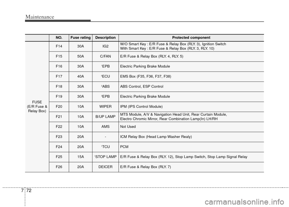
FUSE
(E/R Fuse & Relay Box)
F1430AIG2W/O Smart Key : E/R Fuse & Relay Box (RLY. 3), Ignition Switch
With Smart Key : E/R Fuse & Relay Box (RLY. 3, RLY. 10)
F1550AC/FANE/R Fuse & Relay Box (RLY. 4, RLY. 5)
F1630A1EPBElectric Parking Brake Module
F1740A3ECUEMS Box (F35, F36, F37, F38)
F1830A2ABSABS Control, ESP Control
F1930A2EPBElectric Parking Brake Module
F2010AWIPERIPM (IPS Control Module)
F2110AB/UP LAMPMTS Module, A/V & Navigation Head Unit, Rear Curtain Module,
Electro Chromic Mirror, Rear Combination Lamp(In) LH/RH
F2210AAMSNot Used
F2320A-ICM Relay Box (Head Lamp Washer Realy)
F2420A1TCUPCM
F2515A1STOP LAMPE/R Fuse & Relay Box (RLY. 12), Stop Lamp Switch, Stop Lamp Signal Relay
F2620ADEICERE/R Fuse & Relay Box (RLY. 7)
Page 386 of 415
773
Maintenance
NO.Fuse ratingDescriptionProtected component
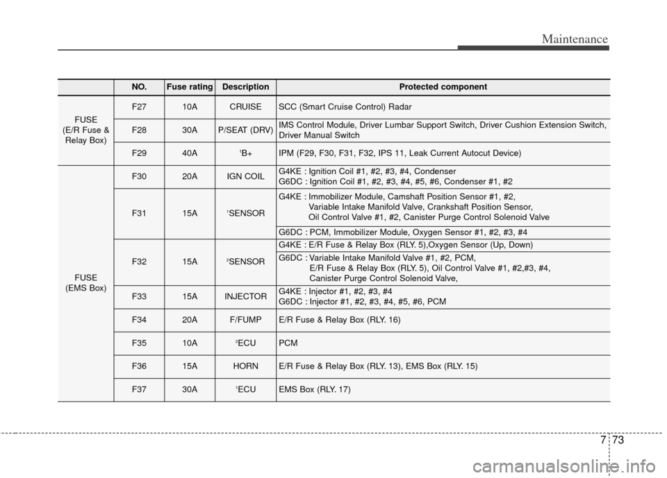
FUSE
(E/R Fuse & Relay Box)
F2710ACRUISESCC (Smart Cruise Control) Radar
F2830AP/SEAT (DRV)IMS Control Module, Driver Lumbar Support Switch, Driver Cushion Extension Switch,
Driver Manual Switch
F2940A1B+IPM (F29, F30, F31, F32, IPS 11, Leak Current Autocut Device)
FUSE
(EMS Box)
F3020AIGN COILG4KE : Ignition Coil #1, #2, #3, #4, Condenser
G6DC : Ignition Coil #1, #2, #3, #4, #5, #6, Condenser #1, #2
F3115A1SENSOR
G4KE : Immobilizer Module, Camshaft Position Sensor #1, #2, Variable Intake Manifold Valve, Crankshaft Position Sensor,
Oil Control Valve #1, #2, Canister Purge Control Solenoid Valve
G6DC : PCM, Immobilizer Module, Oxygen Sensor #1, #2, #3, #4
F3215A2SENSOR
G4KE : E/R Fuse & Relay Box (RLY. 5),Oxygen Sensor (Up, Down)
G6DC : Variable Intake Manifold Valve #1, #2, PCM, E/R Fuse & Relay Box (RLY. 5), Oil Control Valve #1, #2,#3, #4,
Canister Purge Control Solenoid Valve,
F3315AINJECTORG4KE : Injector #1, #2, #3, #4
G6DC : Injector #1, #2, #3, #4, #5, #6, PCM
F3420AF/FUMPE/R Fuse & Relay Box (RLY. 16)
F3510A2ECUPCM
F3615AHORNE/R Fuse & Relay Box (RLY. 13), EMS Box (RLY. 15)
F3730A1ECUEMS Box (RLY. 17)
Page 410 of 415
I5
Index
Washer fluid . . . . . . . . . . . . . . . . . . . . . . . . . . . . . . . 7-35
Fog light . . . . . . . . . . . . . . . . . . . . . . . . . . . . . . . . . . . 4-\
102
Folding the outside rearview mirror . . . . . . . . . . . . . . . 4-50
Front seat adjustment - power . . . . . . . . . . . . . . . . . . . . 3-4
Fuel Economy . . . . . . . . . . . . . . . . . . . . . . . . . . . . . . . . 4-73
Fuel filler lid . . . . . . . . . . . . . . . . . . . . . . . . . . . . . . . . . 4-29
Fuel Gauge . . . . . . . . . . . . . . . . . . . . . . . . . . . . . . . . . . 4-55\
Fuel requirements . . . . . . . . . . . . . . . . . . . . . . . . . . . . . . 1-3
Fuse switch . . . . . . . . . . . . . . . . . . . . . . . . . . . . . . . . . . 7-63\
Fuses . . . . . . . . . . . . . . . . . . . . . . . . . . . . . . . . . . . . \
. . . 7-61 Fuse switch . . . . . . . . . . . . . . . . . . . . . . . . . . . . . . . . 7-63
Fuse/relay panel description. . . . . . . . . . . . . . . . . . . 7-65
Instrument panel fuse . . . . . . . . . . . . . . . . . . . . . . . . 7-65
Main fuse . . . . . . . . . . . . . . . . . . . . . . . . . . . . . . . . . 7-64
Multi fuse . . . . . . . . . . . . . . . . . . . . . . . . . . . . . . . . . 7-64
Gauges . . . . . . . . . . . . . . . . . . . . . . . . . . . . . . . . . . . . \
. 4-54
Glove box . . . . . . . . . . . . . . . . . . . . . . . . . . . . . . . . . . 4-13\
0
Glove box lamp. . . . . . . . . . . . . . . . . . . . . . . . . . . . . . 4-110
Gross vehicle weight. . . . . . . . . . . . . . . . . . . . . . . . . . . . 8-3
Hazard warning flasher . . . . . . . . . . . . . . . . . . . . . . . . . 4-96
Hazardous driving conditions . . . . . . . . . . . . . . . . . . . . 5-66
Headlamp escort function . . . . . . . . . . . . . . . . . . . . . . . 4-97 Headlight leveling device . . . . . . . . . . . . . . . . . . . . . . 4-103
Headrest(front) . . . . . . . . . . . . . . . . . . . . . . . . . . . . . . . . 3-9
Headrest(rear) . . . . . . . . . . . . . . . . . . . . . . . . . . . . . . . . 3-11
Heated steering wheel. . . . . . . . . . . . . . . . . . . . . . . . . . 4-39
Heater . . . . . . . . . . . . . . . . . . . . . . . . . . . . . . . . . . . . \
. 4-113
Height adjustment . . . . . . . . . . . . . . . . . . . . . . . . . . . . . 3-16
High - beam operation . . . . . . . . . . . . . . . . . . . . . . . . 4-110
Highway driving . . . . . . . . . . . . . . . . . . . . . . . . . . . . . . 5-69
Hill-start assist control (HAC) . . . . . . . . . . . . . . . . . . . 5-33
HomeLink system . . . . . . . . . . . . . . . . . . . . . . . . . . . . . 4-40
Hood . . . . . . . . . . . . . . . . . . . . . . . . . . . . . . . . . . . . \
. . . 4-27
Horn . . . . . . . . . . . . . . . . . . . . . . . . . . . . . . . . . . . . \
. . . 4-39
How to use this manual . . . . . . . . . . . . . . . . . . . . . . . . . 1-2
Immobilizer system . . . . . . . . . . . . . . . . . . . . . . . . . . . 4-11
Indicator light . . . . . . . . . . . . . . . . . . . . . . . . . . . . . . . . 4-86
Inflation and non inflation conditions . . . . . . . . . . . . . 3-48
Inside rearview mirror . . . . . . . . . . . . . . . . . . . . . . . . . 4-40
Instrument cluster . . . . . . . . . . . . . . . . . . . . . . . . . . . . . 4-52
Gauges . . . . . . . . . . . . . . . . . . . . . . . . . . . . . . . . . . . 4-\
54
Instrument panel illumination . . . . . . . . . . . . . . . . . 4-53
LCD Display Control . . . . . . . . . . . . . . . . . . . . . . . . 4-53
Transaxle Shift Indicator . . . . . . . . . . . . . . . . . . . . . 4-58
Instrument panel fuse . . . . . . . . . . . . . . . . . . . . . . . . . . 7-62
Instrument panel overview . . . . . . . . . . . . . . . . . . . . . . . 2-5
Interior care. . . . . . . . . . . . . . . . . . . . . . . . . . . . . . . . . . 7-79\
G
H
I