child seat KIA CADENZA 2019 Owner's Manual
[x] Cancel search | Manufacturer: KIA, Model Year: 2019, Model line: CADENZA, Model: KIA CADENZA 2019Pages: 518, PDF Size: 11.08 MB
Page 71 of 518

Safety features of your vehicle
54
3
Driver's and passenger's front
air bagYour vehicle is equipped with an
Advanced Supplemental Restraint
(Air Bag) System and lap/shoulder
belts at both the driver and passen-
ger seating position.
The indication of the system's pres-
ence are the letters "AIR BAG" located
on the air bag pad cover on the steer-
ing wheel and the passenger's side
front panel pad above the glove box.
The SRS consists of air bags
installed under the pad covers in the
center of the steering wheel and the
passenger's side front panel above
the glove box.
The purpose of the SRS is to provide
the vehicle's driver and/or the front
passenger with additional protection
than that offered by the seat belt sys-
tem alone in case of a frontal impact
of sufficient severity. The SRS uses
sensors to gather information about
the driver's and front passenger's
seat belt usage and impact severity.
The seat belt buckle sensors deter-
mine if the driver and front passen-
ger's seat belts are fastened. These sensors provide the ability to
control the SRS deployment based on
whether or not the seat belts are fas-
tened, and how severe the impact is.
The advanced SRS offers the ability
to control the air bag inflation with
two levels. A first stage level is pro-
vided for moderate-severity impacts.
A second stage level is provided for
more severe impacts.
The passenger’s front air bag is
designed to help reduce the injury of
children sitting close to the instru-
ment panel in low speed collisions.
However, children are safer if they
are restrained in the rear seat.
According to the impact severity and
seat belt usage, the SRSCM (SRS
Control Module) controls the air bag
inflation. Failure to properly wear
seat belts can increase the risk or
severity of injury in an accident.
✽ ✽
NOTICE
The driver’s hands should be placed on
the steering wheel at the 9:00 and 3:00
positions. The passenger’s arm and
hands should be placed on their laps.
OYG036069L
■ Driver’s front air bag
■Driver’s knee air bagOYG036036
OYG036037
■Passenger’s front air bag
Page 231 of 518
4149
Features of your vehicle
During mild weather or under condi-
tions where the operation of the seat
warmer is not needed, keep the
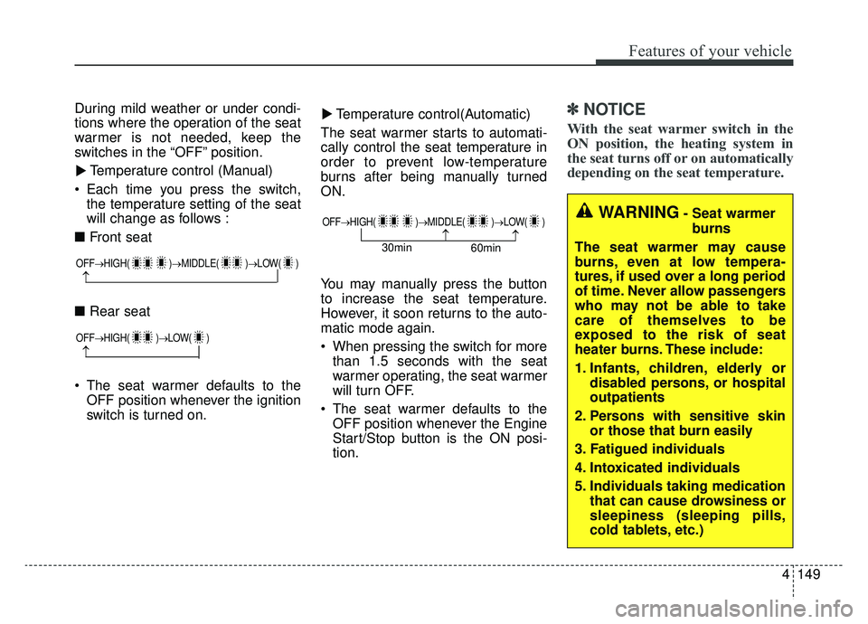
switches in the “OFF” position.Temperature control (Manual)
Each time you press the switch, the temperature setting of the seat
will change as follows :
■ Front seat
■ Rear seat
The seat warmer defaults to the OFF position whenever the ignition
switch is turned on. Temperature control(Automatic)
The seat warmer starts to automati-
cally control the seat temperature in
order to prevent low-temperature
burns after being manually turned
ON.
You may manually press the button
to increase the seat temperature.
However, it soon returns to the auto-
matic mode again.
When pressing the switch for more than 1.5 seconds with the seat
warmer operating, the seat warmer
will turn OFF.
The seat warmer defaults to the OFF position whenever the Engine
Start/Stop button is the ON posi-
tion.✽ ✽ NOTICE
With the seat warmer switch in the
ON position, the heating system in
the seat turns off or on automatically
depending on the seat temperature.▼
▼
OFF→
HIGH( )→ MIDDLE( )→LOW( )
→
OFF→HIGH( )→ LOW( )
→
OFF→HIGH( )→ MIDDLE( )→LOW( )
→→30min
60min
WARNING- Seat warmer
burns
The seat warmer may cause
burns, even at low tempera-
tures, if used over a long period
of time. Never allow passengers
who may not be able to take
care of themselves to be
exposed to the risk of seat
heater burns. These include:
1. Infants, children, elderly or disabled persons, or hospital
outpatients
2. Persons with sensitive skin or those that burn easily
3. Fatigued individuals
4. Intoxicated individuals
5. Individuals taking medication that can cause drowsiness or
sleepiness (sleeping pills,
cold tablets, etc.)
Page 369 of 518
5123
Driving your vehicle
Towing capacity:
We do not recommend using this
vehicle for trailer towing.
Cargo capacity:
The cargo capacity of your vehicle
will increase or decrease depending
on the weight and the number of
occupants.
Steps For Determining CorrectLoad Limit -
1. Locate the statement "The com- bined weight of occupants and
cargo should never exceed XXX
kg or XXX lbs.'' on your vehicle's
placard.
2. Determine the combined weight of the driver and passengers that will
be riding in your vehicle.
3. Subtract the combined weight of the driver and passengers from
XXX kg or XXX lbs.
4. The resulting figure equals the available amount of cargo and lug-
gage load capacity. For example, if
the "XXX" amount equals 1400
lbs. and there will be five 150 lb
passengers in your vehicle, the
amount of available cargo and lug-
gage load capacity is 650 lbs.
(1400-750 (5 x 150) = 650 lbs.) 5. Determine the combined weight of
luggage and cargo being loaded
on the vehicle. That weight may
not safely exceed the available
cargo and luggage load capacity
calculated in Step 4.
6. If your vehicle will be towing a trail- er, load from your trailer will be
transferred to your vehicle. Consult
this manual to determine how this
reduces the available cargo and
luggage load capacity of your
vehicle.
WARNING - Loose cargo
Do not travel with unsecured
blunt objects in the passenger
compartment of your vehicle
(e.g. suit cases or unsecured
child seats). These items may
strike occupant during a sud-
den stop or crash.
Page 512 of 518

I5
Index
Fuses . . . . . . . . . . . . . . . . . . . . . . . . . . . . . . . . . . . . \
. . . 7-51Engine compartment fuse replacement . . . . . . . . . . 7-54
Fuse/relay panel description. . . . . . . . . . . . . . . . . . . 7-57
Inner panel fuse replacement . . . . . . . . . . . . . . . . . . 7-52
Gross vehicle weight. . . . . . . . . . . . . . . . . . . . . . . . . . . . 8-5
Head Up Display (HUD) . . . . . . . . . . . . . . . . . . . . . . 4-105 Description . . . . . . . . . . . . . . . . . . . . . . . . . . . . . . . 4-105
Head up display information . . . . . . . . . . . . . . . . . 4-106
Head up display on/off . . . . . . . . . . . . . . . . . . . . . . 4-106
Head up display setting . . . . . . . . . . . . . . . . . . . . . 4-106
Hood . . . . . . . . . . . . . . . . . . . . . . . . . . . . . . . . . . . . \
. . . 4-37 Closing the hood . . . . . . . . . . . . . . . . . . . . . . . . . . . 4-38
Opening the hood . . . . . . . . . . . . . . . . . . . . . . . . . . . 4-37
How to use this manual . . . . . . . . . . . . . . . . . . . . . . . . . 1-2
If the engine overheats . . . . . . . . . . . . . . . . . . . . . . . . . . 6-7
If the engine will not start . . . . . . . . . . . . . . . . . . . . . . . 6-4 If engine doesn't turn over or turns over slowly . . . . 6-4
If engine turns over normally but does not start . . . . 6-4 If you have a flat tire . . . . . . . . . . . . . . . . . . . . . . . . . . 6-15
Changing tires . . . . . . . . . . . . . . . . . . . . . . . . . . . . . 6-17
Jack and tools . . . . . . . . . . . . . . . . . . . . . . . . . . . . . . 6-15
Removing and storing the spare tire . . . . . . . . . . . . 6-16
Important safety precautions . . . . . . . . . . . . . . . . . . . . . 3-2 Air bag hazards . . . . . . . . . . . . . . . . . . . . . . . . . . . . . 3-2
Always wear your seat belt . . . . . . . . . . . . . . . . . . . . 3-2
Control your speed . . . . . . . . . . . . . . . . . . . . . . . . . . . 3-3
Driver distraction . . . . . . . . . . . . . . . . . . . . . . . . . . . . 3-2
Keep your vehicle in safe condition. . . . . . . . . . . . . . 3-3
Restrain all children . . . . . . . . . . . . . . . . . . . . . . . . . . 3-2
In case of an emergency while driving . . . . . . . . . . . . . . 6-3 If the engine stalls at a crossroad or crossing . . . . . . 6-3
If the engine stalls while driving . . . . . . . . . . . . . . . . 6-3
If you have a flat tire while driving . . . . . . . . . . . . . . 6-3
Instrument cluster . . . . . . . . . . . . . . . . . . . . . . . . . . . . . 4-71 Gauges . . . . . . . . . . . . . . . . . . . . . . . . . . . . . . . . . . . 4-\
73
Instrument cluster control . . . . . . . . . . . . . . . . . . . . 4-72
LCD display control . . . . . . . . . . . . . . . . . . . . . . . . . 4-72
Transaxle Shift Indicator . . . . . . . . . . . . . . . . . . . . . 4-76
Instrument panel overview . . . . . . . . . . . . . . . . . . . . . . . 2-5
Interior features. . . . . . . . . . . . . . . . . . . . . . . . . . . . . . 4-148 Air ventilation seat . . . . . . . . . . . . . . . . . . . . . . . . . 4-150
Clock . . . . . . . . . . . . . . . . . . . . . . . . . . . . . . . . . . . 4-\
158
Coat hook . . . . . . . . . . . . . . . . . . . . . . . . . . . . . . . . 4-156
Cup holder . . . . . . . . . . . . . . . . . . . . . . . . . . . . . . . 4-148
Floor mat anchor (s) . . . . . . . . . . . . . . . . . . . . . . . . 4-157
Luggage net (Holder) . . . . . . . . . . . . . . . . . . . . . . . 4-159
H
I
G