sensor KIA CARNIVAL 2007 Workshop Manual
[x] Cancel search | Manufacturer: KIA, Model Year: 2007, Model line: CARNIVAL, Model: KIA CARNIVAL 2007Pages: 1575, PDF Size: 44.86 MB
Page 938 of 1575

control module. Repair if necessary.
CHECK THE GROUND CIRCUIT.
1.Disconnect the connector from the ABS control module.
2. Check for continuity between terminals 1,4 of the ABS control module harness side connector and ground point.
Is there continuity?
▶ Check the wheel speed sensor circuit.
▶ Repair an open in the wire and ground point.
CHECK THE WHEEL SPEED SENSOR CIRCUIT.
Refer to the DTC troubleshooting procedures.
Is the system operating to specifications ?
▶ Check the hydraulic circuit for leakage.
▶ Repair or replace the wheel speed sensor.
CHECK THE HYDRAULIC CIRCUIT FOR LEAKAGE.
Refer to the hydraulic lines.
Inspect leakage of the hydraulic lines.
Is the system operating to specifications ?
▶ The problem is still occurring, replace the ABS control module.
▶ Replace the leaking hydraulic lines.
DETECTING CONDITION
Trouble Symptoms Possible Cause
Brake operation varies depending on driving conditions and road
surface conditions, so diagnosis can be difficult.However if a normal
DTC is displayed, check the following probable cause. When the a.
Inoperative power source circuit
b. Inoperative wheel speed sensor circuit
Page 939 of 1575

DTC is displayed, check the following probable cause. When the
problem is still occurring, replace the ABS control module.b.
Inoperative wheel speed sensor circuit
c. Inoperative hydraulic circuit for leakage
d. Inoperative HECU
INSPECTION PROCEDURES
DTC INSPECTION
1. Connect the Scan Tool with the data link connector and turn the ignition switch ON.
2. Verify that the system is operating to specifications.
Is the system operating to specifications ?
▶ Check the wheel speed sensor circuit.
▶ Erase the DTC and recheck using Scan Tool.
CHECK THE WHEEL SPEED SENSOR CIRCUIT.
Refer to the DTC troubleshooting procedures.
Is the system operating to specifications ?
▶ Check the stop lamp switch circuit.
▶ Repair or replace the wheel speed sensor.
CHECK THE STOP LAMP SWITCH CIRCUIT.
1. Check that stop lamp lights up when brake pedal is depressed and turns off when brake pedal is released.
2. Measure the voltage between terminal 20 of the ABS control module harness side connector and body ground
when brake pedal is depressed.
Specification: approximately B+
Is the voltage within specification?
▶ Check the hydraulic circuit for leakage.
▶ Repair the stop lamp switch. Repair an open in the wire between the ABS control module and the stop lamp
switch.
CHECK THE HYDRAULIC CIRCUIT FOR LEAKAGE.
Refer to the hydraulic lines.
Inspect leakage of the hydraulic lines.
Is the system operating to specifications ?
▶ The problem is still occurring, replace the ABS control module.
Page 946 of 1575

DTCDESCRIPTION WARNING LAMP
REMARK
ABS EBDESC
C1101 BATTERY VOLTAGE HIGH ООО
C1102 BATTERY VOLTAGE LOW ОО
C1200 FL WHEEL SPEED SENSOR- OPEN/SHORT ОО
C1201 FL WHEEL SENSOR- RANGE/ PERFORMANCE ОО
C1202 FL WHEEL WHEEL SPEED SENSOR- NO SIGNAL ОО
C1203 FR WHEEL SPEED SENSOR- OPEN/SHORT ОО
C1204 FR WHEEL SENSOR- RANGE/ PERFORMANCE ОО
C1205 FR WHEEL SPEED SENSOR- NO SIGNAL ОО
C1206 RL WHEEL SPEED SENSOR- OPEN/SHORT ОО
C1207 RL WHEEL SENSOR- RANGE/ PERFORMANCE ОО
C1208 RL WHEEL SPEED SENSOR- NO SIGNAL ОО
C1209 RR WHEEL SPEED SENSOR- OPEN/SHORT ОО
C1210 RR WHEEL SENSOR- RANGE/ PERFORMANCE ОО
C1211 RR WHEEL SPEED SENSOR- NO SIGNAL ОО
C1213 WHEEL SPEED FREQUENCY ERROR ОО
C1235 PRESSURE SENSOR- ELECTRICAL ОESP
C1237 PRESSURE SENSOR- SIGNAL FAULT ОESP
C1260 STEERING ANGLE SENSOR- SIGNAL ОESP
C1261 STEERING ANGLE SENSOR NOT CALIBRATED ОESP
C1282 YAW RATE & LATERAL G SENSOR- ELECTRICAL ОESP
C1283 YAW RATE & LATERAL G SENSOR- SIGNAL ОESP
C1503 ESP SWITCH ERROR ОESP
C1513 BRAKE LIGHT SWITCH MALFUNCTION О
C1604 ECU HARDWARE ERROR ООО
C1605 CAN CONTROL HARDWARE ERROR ОESP
C1611 CAN TIME OUT- PCM(ECM) ОESP
C1612 CAN TIME OUT- PCM(TCM) ОESP
C1616 CAN BUS OFF ОESP
C1623 CAN TIMEOUT STEERING ANGLE SENSOR ОESP
C1625 CAN TIME OUT- ESP ОESP
C1626 IMPLAUSIBLE CONTROL ООESP
C1702 VARIANT CODING ООО ESP
C2112 VALVE RELAY MALFUNCTION ООО
C2308 FL INLET VALVE MALFUNCTION ООО
C2312 FL OUTLET VALVE MALFUNCTION ООО
C2316 FR INLET VALVE MALFUNCTION ООО
C2320 FR OUTLET VALVE MALFUNCTION ООО
C2324 RL INLET VALVE MALFUNCTION ООО
C2328 RL OUTLET VALVE MALFUNCTION ООО
Page 952 of 1575
Front Wheel Speed Sensor
Page 954 of 1575
2007 > 2.7L V6 GASOLINE >
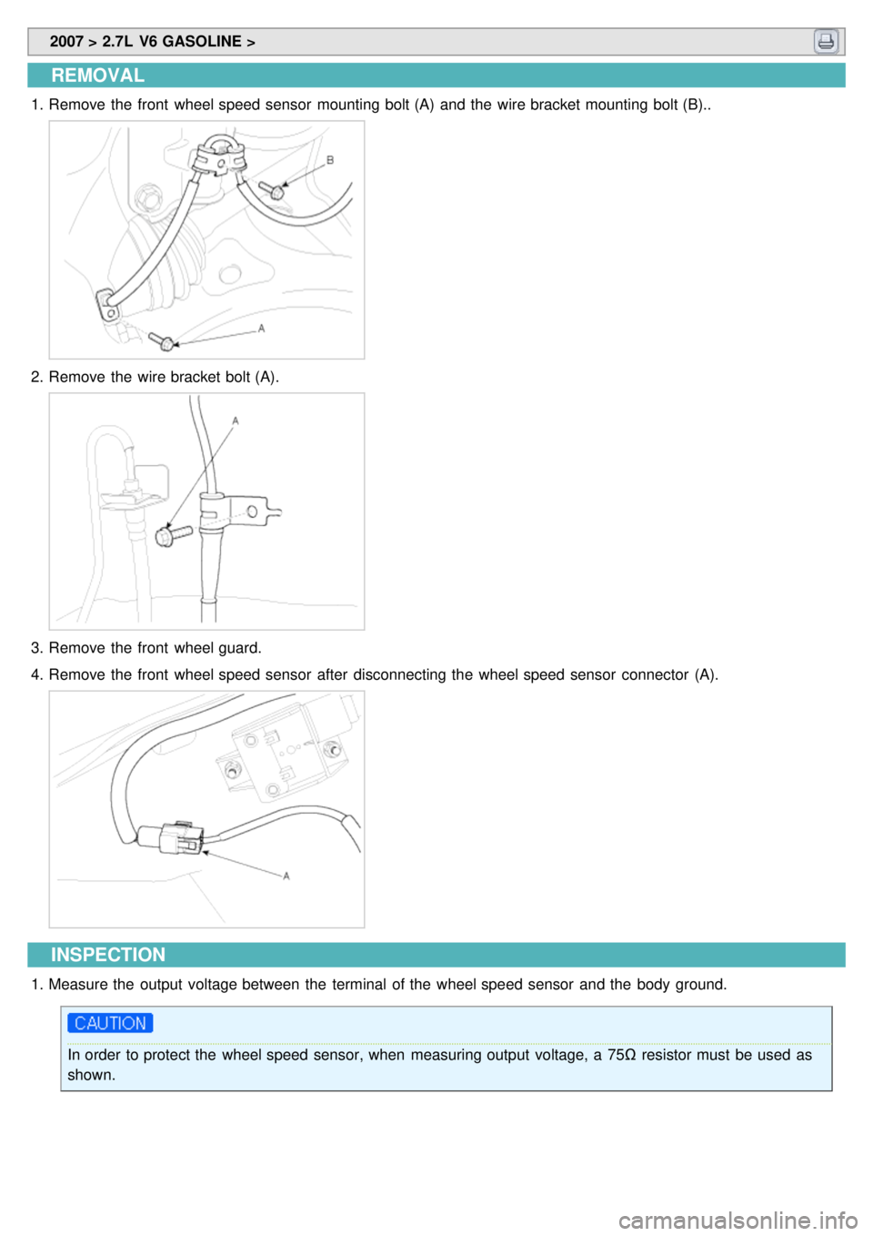
REMOVAL
1.Remove the front wheel speed sensor mounting bolt (A) and the wire bracket mounting bolt (B)..
2.Remove the wire bracket bolt (A).
3.Remove the front wheel guard.
4. Remove the front wheel speed sensor after disconnecting the wheel speed sensor connector (A).
INSPECTION
1.Measure the output voltage between the terminal of the wheel speed sensor and the body ground.
In order to protect the wheel speed sensor, when measuring output voltage, a 75Ω resistor must be used as
shown.
Page 955 of 1575
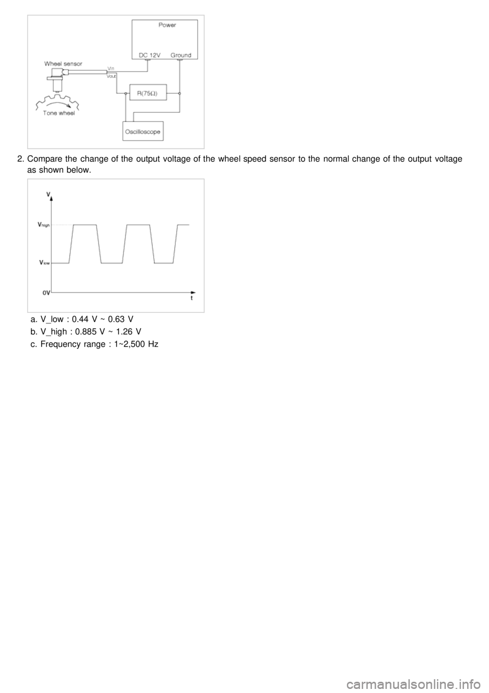
2.Compare the change of the output voltage of the wheel speed sensor to the normal change of the output voltage
as shown below.
a.V_low : 0.44 V ~ 0.63 V
b. V_high : 0.885 V ~ 1.26 V
c. Frequency range : 1~2,500 Hz
Page 956 of 1575
Rear Wheel Speed Sensor
Page 958 of 1575
2007 > 2.7L V6 GASOLINE >
REMOVAL
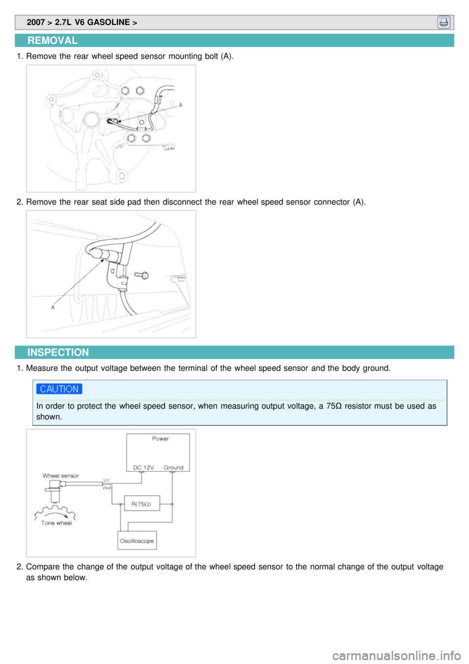
1.Remove the rear wheel speed sensor mounting bolt (A).
2.Remove the rear seat side pad then disconnect the rear wheel speed sensor connector (A).
INSPECTION
1.Measure the output voltage between the terminal of the wheel speed sensor and the body ground.
In order to protect the wheel speed sensor, when measuring output voltage, a 75Ω resistor must be used as
shown.
2. Compare the change of the output voltage of the wheel speed sensor to the normal change of the output voltage
as shown below.
Page 966 of 1575
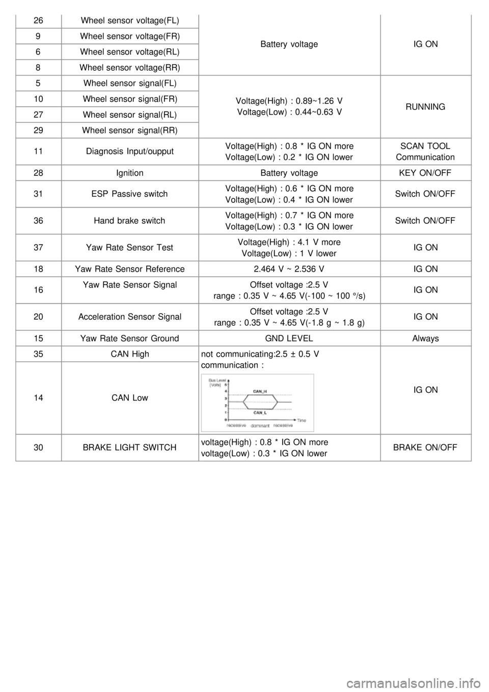
26Wheel sensor voltage(FL)
Battery voltageIG ON
9
Wheel sensor voltage(FR)
6 Wheel sensor voltage(RL)
8 Wheel sensor voltage(RR)
5 Wheel sensor signal(FL)
Voltage(High) : 0.89~1.26 VVoltage(Low) : 0.44~0.63 V RUNNING
10
Wheel sensor signal(FR)
27 Wheel sensor signal(RL)
29 Wheel sensor signal(RR)
11 Diagnosis Input/oupput Voltage(High) : 0.8 * IG ON more
Voltage(Low) : 0.2 * IG ON lower SCAN TOOL
Communication
28 Ignition Battery voltageKEY ON/OFF
31 ESP Passive switch Voltage(High) : 0.6 * IG ON more
Voltage(Low) : 0.4 * IG ON lower Switch ON/OFF
36 Hand brake switch Voltage(High) : 0.7 * IG ON more
Voltage(Low) : 0.3 * IG ON lower Switch ON/OFF
37 Yaw Rate Sensor Test Voltage(High) : 4.1 V more
Voltage(Low) : 1 V lower IG ON
18 Yaw Rate Sensor Reference 2.464 V ~ 2.536 VIG ON
16 Yaw Rate Sensor Signal
Offset voltage :2.5 V
range : 0.35 V ~ 4.65 V(- 100 ~ 100 °/s) IG ON
20 Acceleration Sensor Signal Offset voltage :2.5 V
range : 0.35 V ~ 4.65 V(- 1.8 g ~ 1.8 g) IG ON
15 Yaw Rate Sensor Ground GND LEVELAlways
35 CAN High not communicating:2.5 ± 0.5 V
communication :
IG ON
14 CAN Low
30 BRAKE LIGHT SWITCH voltage(High) : 0.8 * IG ON more
voltage(Low) : 0.3 * IG ON lower BRAKE ON/OFF
Page 967 of 1575

2007 > 2.7L V6 GASOLINE >
description of ESP
Optimum driving safety now has a name : ESP, the Electronic Stability Control.
ESP recognizes critical driving conditions, such as panic reactions in dangerous situations, and stabilizes the vehicle
by wheel- individual braking and engine control intervention with no needfor actuating the brake or the gas pedal.
ESP adds a further function known as Active Yaw Control (AYC) to the ABS, TCS, EBD and ESP functions. Whereas
the ABS/TCS function controls wheel slip during braking and acceleration and, thus, mainly intervenes in the
longitudinal dynamics of the vehicle, active yaw control stabilizes the vehicle about its vertical axis.
This is achieved by wheel individual brake intervention and adaptation of the momentary engine torque with no need
for any action to be taken by the driver.
ESC essentially consists of three assemblies : the sensors, the electronic control unit and the actuators.
Of course, the stability control feature works under all driving and operating conditions. Under certain driving
conditions, the ABS/TCS function can be activated simultaneously with the ESP function in response to a command
by the driver.
In the event of a failure of the stability control function, the basic safety function, ABS, is still maintained.
DESCRIPTION OF ESP CONTROL
ESP system includes ABS/EBD, TCS and AYC (Active yaw control) function.
ABS/EBD function : The ECU changes the active sensor signal (current shift) coming from the four wheel sensors to
the square waveform.By using the input of above signals, the ECU calculates the vehicle speed and the acceleration
& deceleration of the four wheels.And, the ECU judges whether the ABS/EBD should be actuated or not.
TCS function prevents the wheel slip of drive direction by adding the brake pressure and engine torque reduction via
CAN communication.TCS function uses the wheel speed sensor signal to determine the wheel slip as far as ABS
function.
AYC function prevents unstable maneuver of the vehicle. To determine the vehicle maneuver, AYC function uses the
maneuver sensor signals(Yaw Rate Sensor, Lateral Acceleration Sensor, Steering Wheel Angle Sensor).If vehicle
maneuver is unstable (Over Steer or Under Steer), AYC function applies the brake pressure on certain wheel, and
send engine torque reduction signal by CAN.
After the key - on, the ECU continually diagnoses the system failure. (self- diagnosis)If the system failure is detected,
the ECU informs driver of the system failure through the BRAKE/ABS/ESP warning lamp. (fail- safe warning)