ECO mode KIA CARNIVAL 2007 User Guide
[x] Cancel search | Manufacturer: KIA, Model Year: 2007, Model line: CARNIVAL, Model: KIA CARNIVAL 2007Pages: 1575, PDF Size: 44.86 MB
Page 737 of 1575

2007 > 2.7L V6 GASOLINE >
INSPECTION
Inspect the PTC operation by confirmation logic as below.
1. Entering method
(1) Set the floor mode, maximum heating
(2) Turn off the blower switch
(3) Press the intake button more than 5 times.
(4) Indicator of entire button is flashed with an interval of 0.5 seconds continuously (Manual).
Graphics of the entire LCD display switch on and off with an interval of 0.5 seconds continuously (Automatic)
(5) Confirm the PTC operation by operating the blower switch
Manual : 1~4 step, Automatic: 1~8step.
(6) Each PTC relay is operated with an interval of 3 seconds.
(7) Execute the PTC operation by confirmation logic for 30 seconds.
2. Cancellation method
(1) Select the A/C button or intake button.
(2) IG "OFF".
(3) Cancel the logic after 30 seconds automatically.
3. If the PTC operation is not operated, substitute with a known- good PTC and check for proper operation.
If the problem is corrected, replace the PTC.
Page 929 of 1575
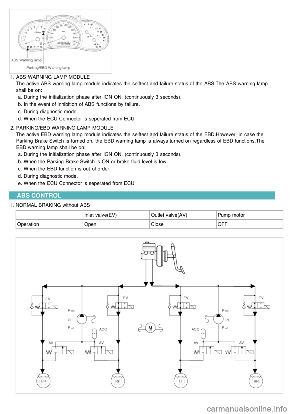
1.ABS WARNING LAMP MODULE
The active ABS warning lamp module indicates the selftest and failure status of the ABS.The ABS warning lamp
shall be on:
a. During the initialization phase after IGN ON. (continuously 3 seconds).
b. In the event of inhibition of ABS functions by failure.
c. During diagnostic mode.
d. When the ECU Connector is seperated from ECU.
2. PARKING/EBD WARNING LAMP MODULE
The active EBD warning lamp module indicates the selftest and failure status of the EBD.However, in case the
Parking Brake Switch is turned on, the EBD warning lamp is always turned on regardless of EBD functions.The
EBD warning lamp shall be on:
a. During the initialization phase after IGN ON. (continuously 3 seconds).
b. When the Parking Brake Switch is ON or brake fluid level is low.
c. When the EBD function is out of order.
d. During diagnostic mode.
e. When the ECU Connector is seperated from ECU.
ABS CONTROL
1.NORMAL BRAKING without ABS
Inlet valve(EV)Outlet valve(AV)Pump motor
Operation OpenCloseOFF
Page 944 of 1575
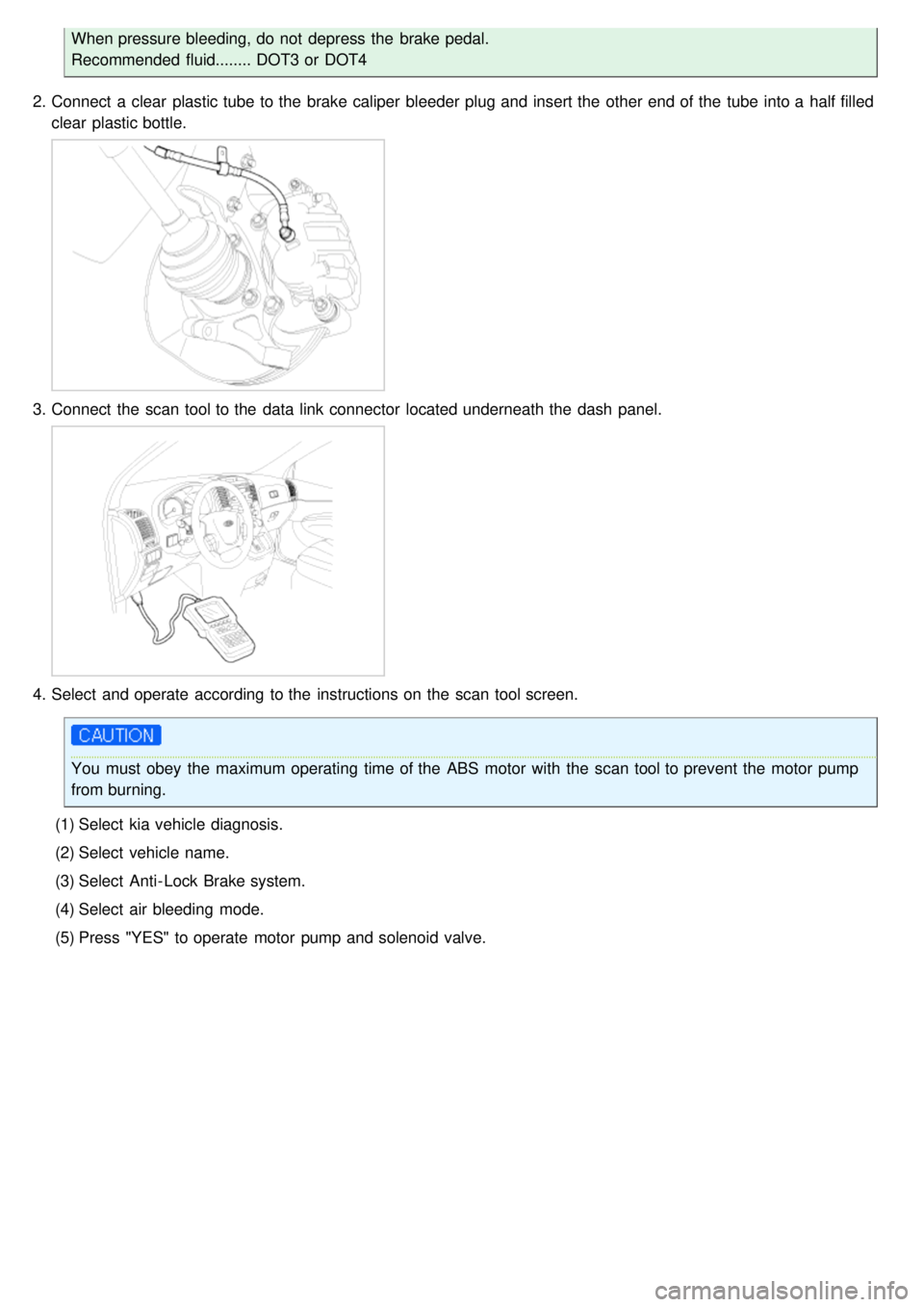
When pressure bleeding, do not depress the brake pedal.
Recommended fluid........ DOT3 or DOT4
2. Connect a clear plastic tube to the brake caliper bleeder plug and insert the other end of the tube into a half filled
clear plastic bottle.
3.Connect the scan tool to the data link connector located underneath the dash panel.
4.Select and operate according to the instructions on the scan tool screen.
You must obey the maximum operating time of the ABS motor with the scan tool to prevent the motor pump
from burning.
(1) Select kia vehicle diagnosis.
(2) Select vehicle name.
(3) Select Anti- Lock Brake system.
(4) Select air bleeding mode.
(5) Press "YES" to operate motor pump and solenoid valve.
Page 974 of 1575
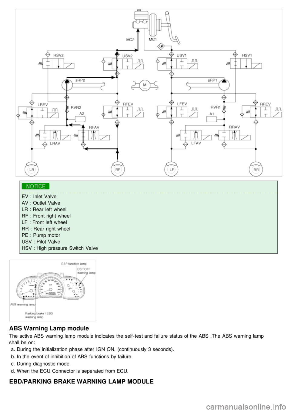
EV : Inlet Valve
AV : Outlet Valve
LR : Rear left wheel
RF : Front right wheel
LF : Front left wheel
RR : Rear right wheel
PE : Pump motor
USV : Pilot Valve
HSV : High pressure Switch Valve
ABS Warning Lamp module
The active ABS warning lamp module indicates the self - test and failure status of the ABS .The ABS warning lamp
shall be on:a. During the initialization phase after IGN ON. (continuously 3 seconds).
b. In the event of inhibition of ABS functions by failure.
c. During diagnostic mode.
d. When the ECU Connector is seperated from ECU.
EBD/PARKING BRAKE WARNING LAMP MODULE
Page 975 of 1575
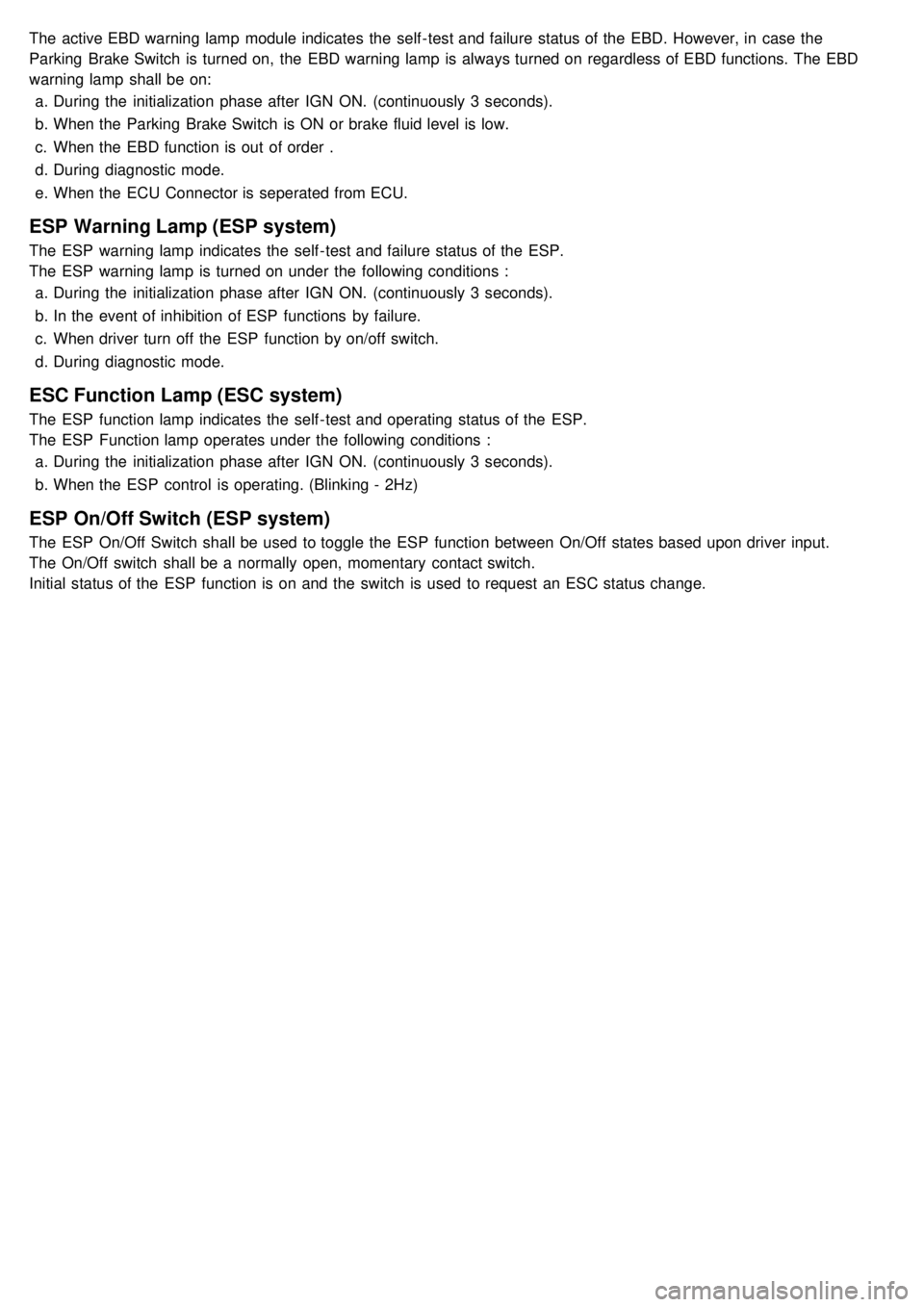
The active EBD warning lamp module indicates the self - test and failure status of the EBD. However, in case the
Parking Brake Switch is turned on, the EBD warning lamp is always turned on regardless of EBD functions. The EBD
warning lamp shall be on:a. During the initialization phase after IGN ON. (continuously 3 seconds).
b. When the Parking Brake Switch is ON or brake fluid level is low.
c. When the EBD function is out of order .
d. During diagnostic mode.
e. When the ECU Connector is seperated from ECU.
ESP Warning Lamp (ESP system)
The ESP warning lamp indicates the self - test and failure status of the ESP.
The ESP warning lamp is turned on under the following conditions :
a. During the initialization phase after IGN ON. (continuously 3 seconds).
b. In the event of inhibition of ESP functions by failure.
c. When driver turn off the ESP function by on/off switch.
d. During diagnostic mode.
ESC Function Lamp (ESC system)
The ESP function lamp indicates the self - test and operating status of the ESP.
The ESP Function lamp operates under the following conditions :
a. During the initialization phase after IGN ON. (continuously 3 seconds).
b. When the ESP control is operating. (Blinking - 2Hz)
ESP On/Off Switch (ESP system)
The ESP On/Off Switch shall be used to toggle the ESP function between On/Off states based upon driver input.
The On/Off switch shall be a normally open, momentary contact switch.
Initial status of the ESP function is on and the switch is used to request an ESC status change.
Page 1229 of 1575
switch, the status of the ABS EBD warning, the status of the brake fluid sensor and the speed of the vehicle.
The IPM sends the park brake indicator control on the CAN network.
The indicator is lighted if the vacuum switch or ABS EBD warning are on or brake fluid sensor is low or park brake
switch is on.
If the speed of the vehicle is over 10 km/h and ignition switch is on the status RUN the park brake indicator control is
blinking at 50% duty in 0.6 second if Parking Brake switch Input is active. In this case Vacuum switch, ABS EBD
warning and Brake Fluid sensor are ignored.
The park brake indicator is blinking on the same time that the chime is ringing. If a CAN signal among Vacuum switch,
EBD warning or Brake Fluid Sens switch is INVALID, out of range or not received this CAN signal is considered to be
OFF.
If VehicleSpeed CAN signal is INVALID or not received, it is considered to be 0 kph.
Charging Voltage Control
The IPM receives on analog input the voltage of generator and sends a warning.
When the voltage of generator L pass strictly above 10V, the state of the CAN variable.
Turn Indicators Status
The status of the turn indicators are sent on the CAN network when the CAN network is available.
High Beam Status
The status of the high beam is sent on the CAN network when the CAN network is available.
Front Fog Lamp Status
The status of the front fog lamp (lightning and state of the bulbs) is sent on the CAN network when the CAN network
is available.
Doors Open Warning
The RAM receives on digital input the status of the driver door open switch and sends it on the CAN network.
The RAM receives on digital input the status of the passenger door open switch and sends it on the CAN network.
The RAM receives on digital input the status of the left sliding door open switch and sends it on the CAN network.
The RAM receives on digital input the status of the right sliding door open switch and sends it on the CAN network.
When vehicle speed is under 10 kph, with ignition key not inserted and any door OPEN, DoorsOpenWngCtrl stays ON
for 20 min and then is turned OFF.
Tailgate Open Switch Status
When vehicle speed is under 10 kph, ignition key is inserted and Tailgate open switch is OPEN, Tailgate Open
warning stays ON forever (IPM can enter sleep mode).
When vehicle speed is under 10 kph, with ignition key not inserted and lgate open switch is OPEN, Tailgate Open
warning stays ON for 20 min and then is turned OFF.
Chime Control
1.The chime warns the driver that a problem is occurred.
These warning are:
a. Seat belt
b. Parking on
c. Over speed
d. Key reminder
e. Light Warning
f. Doors Open
g. Tailgate open warning
2. Chime sound priority:
a. 1st : Seatbelt warning
b. 2nd : Overspeed warning
c. 3rd : Door open warning
d. 4th : T/Gate open warning
e. 5th : Key operated warning
f. 6th : Parking Brake warning
Page 1234 of 1575
CLOSE signal.
b. RAM will pass this signal to LH PSD and RH PSD then the burglar alarm state is decided depending on the
vehicle condition.
f. PTG open/close
a. Only with the information received by RKE, the burglar alarm system cannot distinguish the OPEN signal from
CLOSE signal.
b. RAM will pass this signal to PTG module then the burglar alarm state is decided depending on the vehicle
condition.
g. Panic by key fob
a. Whenever this signal is received, the PANIC function is activated (unless the system is already in an ALARM
state).
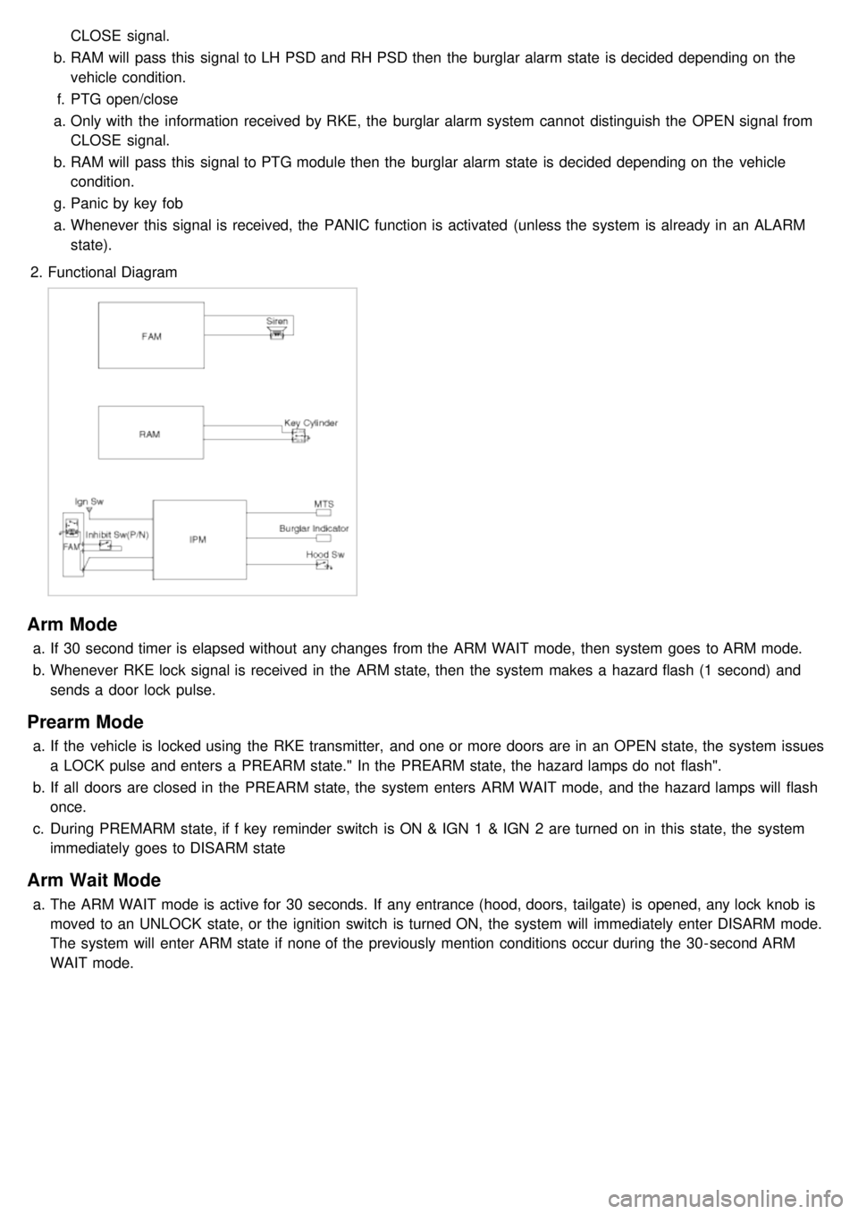
2. Functional Diagram
Arm Mode
a.If 30 second timer is elapsed without any changes from the ARM WAIT mode, then system goes to ARM mode.
b. Whenever RKE lock signal is received in the ARM state, then the system makes a hazard flash (1 second) and
sends a door lock pulse.
Prearm Mode
a.If the vehicle is locked using the RKE transmitter, and one or more doors are in an OPEN state, the system issues
a LOCK pulse and enters a PREARM state." In the PREARM state, the hazard lamps do not flash".
b. If all doors are closed in the PREARM state, the system enters ARM WAIT mode, and the hazard lamps will flash
once.
c. During PREMARM state, if f key reminder switch is ON & IGN 1 & IGN 2 are turned on in this state, the system
immediately goes to DISARM state
Arm Wait Mode
a.The ARM WAIT mode is active for 30 seconds. If any entrance (hood, doors, tailgate) is opened, any lock knob is
moved to an UNLOCK state, or the ignition switch is turned ON, the system will immediately enter DISARM mode.
The system will enter ARM state if none of the previously mention conditions occur during the 30- second ARM
WAIT mode.
Page 1235 of 1575

T1 : 0.5 sec
T2 : 1.0 ± 0.1 sec
Disarm Mode
a.If RKE unlock signal is received, then UNLOCK output is issued together with the flashing of hazard lamp (two
times) and the system enters into the DISARM condition.
b. When entering into DISARM from ALARM state, current alarm will be cancelled and burglar alarm relay drive
output is turned off.
c. When RKE unlock signal is received again in the DISARM state, UNLOCK output is issued again and hazard lamp
is flashed also (two times).
Alarm Mode
a.If one or more of entrances are opened in the ARM or REARM state, then Burglar alarm relay drive output is
turned ON in order to inhibit the start condition, and hazard lamp and siren are activated for once of 27 seconds
duration.
b. Siren output and hazard lamp should be synchronized to get the same output period.
c. Even though all the doors are closed during alarm, alarm continues to operate it for the remaining time.
d. When there is a new attack (with one of the entrance is still open) in the vehicle after completing the alarm output,
alarm should not be started again.
T1 : 27 sec ( - 0, +3sec)
T2 : 0.5 ± 0.1 sec
After Alarm State
a.If ALARM cycle is elapsed, the system goes into AFTER ALARM state.
b. During this state,
a. Burglar alarm relay drive output maintains ON.
b. Siren and hazard lamp output are stopped.
c. If another entry is opened during the AFTER ALARM state, the burglar alarm relay drive output remains ON, but
the siren will not be re- activated.
Rearm State
a.If all entrances are is closed during AFTER ALARM state, the system goes into REARM state.
Page 1236 of 1575

Battery Removal
a.If the battery is removed with the system in the ARM state, the system will be placed into the ARM state upon
battery reconnect.
b. The ALARM state will be re- activated if the battery is disconnected, then reconnected, with the system in an
ALARM state.
c. If the battery is disconnected and reconnected with the system in AFTER ALARM state, the alarm will be re-
activated.
d. The system will enter DISARM mode if the battery is disconnected during the ALARM WAIT state.
Panic
a.If RKE PANIC signal is received, Siren output and hazard lamp operate for 27 seconds and the system return to
the previous state as soon as the PANIC function finishes.
b. The PANIC function will be stopped if any RKE signal is received during PANIC activation..
c. If Key reminder switch is ON during PANIC function is operating, PANIC is stopped immediately.
d. If the system goes to ALARM mode during PANIC function is operating, PANIC is stopped immediately and then
ALARM function should be activated.
e. During ALARM state;
If RKE PANIC signal is received, ALARM mode is maintained and PANIC function should be ignored. ALARM has
higher priority than PANIC function.
f. During AFTER_ALARM state;
If RKE PANIC signal is received, AFTR_ALARM mode is maintained and PANIC function should be activated.
Safe & Rescue Mode
The goal of those modes is to be able to cope with failures that may happen on some of the most critical
functionalities (for the driver security) of the system.
Safe Mode
The safe mode is entered in case of system problems such as:
a. Incoherent inputs on monitored signals. In this case, safe mode is the debouncing time before the inputs are
considered INVALID. Note that today, we have no way to detect if the rain/light sensor is in working operation or
not. It means that a driver action will be required in case of failure of this sensor;
b. Loss of the CAN frame containing the monitored signal:
c. Loss of the CAN network: CAN goes to BUS OFF state, safe mode is the time necessary for detecting the BUS
OFF state.
In all cases, the action in safe mode is to maintain the previous state of the system (for lighting and wiping). The list of
monitored signals is the same as in rescue mode
Exiting Safe Mode
The software safe mode is exited and the module goes back to the normal mode when: a. On IPM, hardware inputs return to a coherent state;
b. The lost CAN signal comes back while timeout has not elapsed;
c. The CAN network returns to a normal state without reaching BUS OFF state.
Software safe mode is also exited when the software rescue mode is entered (problem does not disappear).
Hardware safe mode is exited and the module goes back to normal mode if the internal problem disappears (watchdog
is properly triggered again). If the problem stays, hardware safe mode is exited to enter hardware rescue mode.
Rescue Modes
The rescue mode consists in activating some safety functions when IGN2 = ON: a. Switch on the low beams (FAM), park lamps (FAM), tail lamps (RAM) and cluster backlighting (IPM);
b. Unlock of all the doors when the rescue mode is entered with IGN2 = ON
c. Front wipers do not need to be turned on by software in rescue mode because wipers can be turned on by
manually setting the MF switch to low speed. The FAM software must keep the same state as before entering the
rescue mode.
d. When IGN2 = OFF, low beams, park/tail lamps and cluster backlighting are turned off.
Entering Rescue Modes
Page 1259 of 1575

2007 > 2.7L V6 GASOLINE >
DESCRIPTION
An optimal seat position set by a driver can be memorized in P/seat unit by memory SW and position SW, which
enables restoration of seat position set by the driver despite seat adjustments.
Furthermore, data is transmitted between P/seat and IPM, DDM, ADM, RAM, FAM, CLUSTER through CAN BUS.
Seat position presets cannot be recalled while driving. An emergency stop function is provided; additional functions are
described below.
1. It conducts manual operation of seat by CAN BUS data transmitted by DDM as well as that of adjustable pedal by
CAN BUS data transmitted by IPM received when operating SW manually.
2. Manual SW behavior when communication stops (back- up behavior)
a. Slide front/rear
b. Recline front/rear
c. Position control of slide motor is possible by manual SW even in case of congestion in CPU or removal of a
fuse for P/seat unit B.
3. 2 memory locations are provided for storing seat, outside mirror, and adjustable pedal presets.
4. The driver seat can be set to slide rearward when the ignition key is removed, and forward when the key is
inserted.
5. 2 additional presets for seat, mirror, and adjustable pedal position can be stored with the RKE transmitter.
OPERATION
MANUAL OPERATION
Manual operation of the driver seat and adjustable pedals is possible provided the transaxle is in 'P' range and the
vehicle speed is 0 MPH. Operation of the manual controls overrides any automatic operation commanded via CAN.
MEMORY OPERATION
1. Pressing the 'M' button on the control panel will place the system into memory storage mode and will result in a
single pulse from the output buzzer.
2. If one of the memory location buttons is pressed and held within 5 seconds of pressing the 'M' button, the output
buzzer will pulse twice to indicate successful storage of seat, mirror, and adjustable pedal positions.
3. The ignition switch must be in the RUN or START position, the vehicle speed must be 0 MPH, and the transaxle
must be in 'P' range to store memory presets.
4. Pressing the 'M' button while recalling a stored preset will halt the preset recall operation.
5. Memory will be cleared if battery is removed.
MEMORY REPLAY OPERATION
1.Pressing one of the memory location buttons will result in the driver seat, outside mirrors, and adjustable pedals
being positioned based on the stored preset data.
2. The ignition switch must be in the RUN position, the transaxle must be in 'P' range, the vehicle speed must be 0
MPH, and the manual functions must not be in operation to recall stored presets.
3. Others
a. Play operation not recorded in the position switch will not be conducted and there will be no buzzer output.
b. If other data is received during preset recall operation, the most recent preset recall signal will take
precedence.
c. If engine is started during preset recall operation, halt preset recall operation, and resume it toward target
position 100ms after Ignition switch is returned to "RUN". However, if the START state lasts over 5 sec., it will
not resume even after returning to RUN.
d. If preset recall order is received during engine start, preset recall operation is inhibited.
e. If input from manual switch for seat and adjust pedal occurs during preset recall operation of seat and adjust
pedal, halt all their preset recall operations.
f. If an error occurs during manual operation of seat and adjust pedal, delete Memory.