turn signal KIA CEED 2010 Owners Manual
[x] Cancel search | Manufacturer: KIA, Model Year: 2010, Model line: CEED, Model: KIA CEED 2010Pages: 442, PDF Size: 28.25 MB
Page 9 of 442
Introduction
6
1
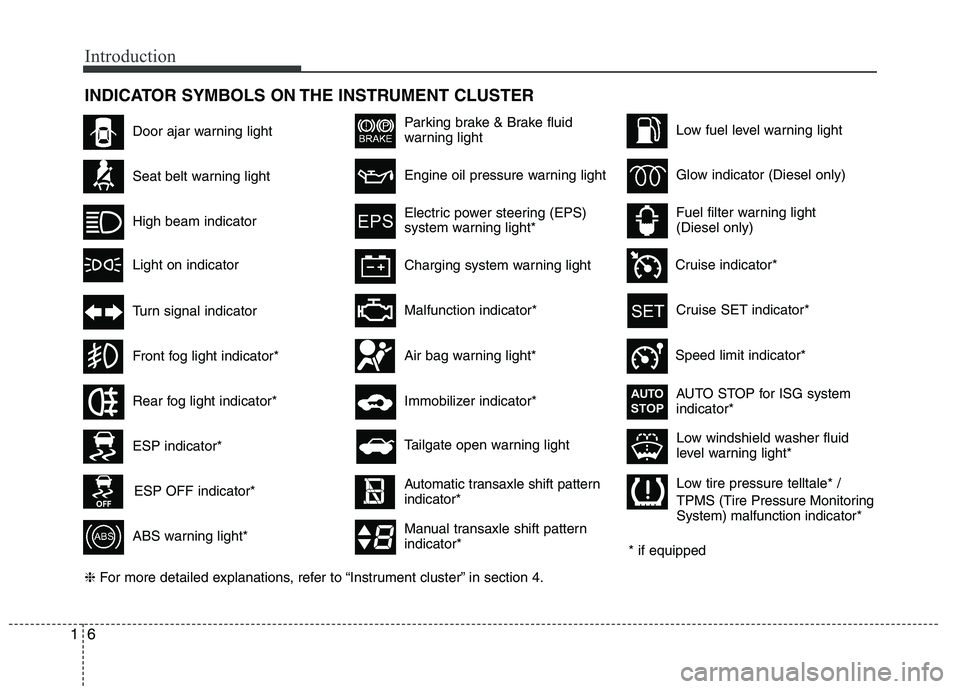
INDICATOR SYMBOLS ON THE INSTRUMENT CLUSTER
Seat belt warning light
High beam indicator
Turn signal indicator
ABS warning light*
Parking brake & Brake fluid
warning light
Malfunction indicator*
Immobilizer indicator*
Low fuel level warning light
Glow indicator (Diesel only)
Fuel filter warning light (Diesel only)
* if equipped
Tailgate open warning light
❈ For more detailed explanations, refer to “Instrument cluster” in section 4.
Charging system warning light
Door ajar warning light
ESP indicator*
ESP OFF indicator*
Front fog light indicator*
Engine oil pressure warning light
Electric power steering (EPS)
system warning light*
Air bag warning light*
Low tire pressure telltale* /
TPMS (Tire Pressure Monitoring System) malfunction indicator*
Rear fog light indicator*
Cruise SET indicator*
Speed limit indicator* AUTO STOP for ISG system indicator*
Cruise indicator*
AUTOSTOP
Low windshield washer fluid
level warning light*
Light on indicator
Automatic transaxle shift pattern indicator*
Manual transaxle shift pattern indicator*
Page 12 of 442
23
Your vehicle at a glance
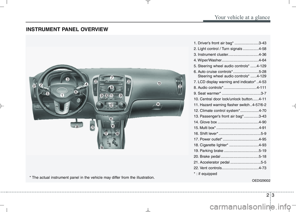
INSTRUMENT PANEL OVERVIEW
1. Driver’s front air bag* .......................3-43
2. Light control / Turn signals ...............4-58
3. Instrument cluster.............................4-36
4. Wiper/Washer ...................................4-64
5. Steering wheel audio controls* ......4-129
6. Auto cruise controls* .........................5-28
Steering wheel audio controls* ......4-129
7. LCD display warning and indicator* .. 4-53
8. Audio controls* ................................4-111
9. Seat warmer* .....................................3-7
10. Central door lock/unlock button......4-11
11. Hazard warning flasher switch .. 4-57/6-2
12. Climate control system*..................4-70
13. Passenger’s front air bag* ..............3-43
14. Glove box .......................................4-90
15. Multi box* ...........................................4-91
16. Shift lever* ........................................5-9
17. Power outlet* ..................................4-95
18. Cigarette lighter* ............................4-93
19. Parking brake .................................5-19
20. Brake pedal ....................................5-18
21. Accelerator pedal .............................5-5
22. Vent controls...................................4-73
* : if equipped
OED029002
* The actual instrument panel in the vehicle may differ from the illustration.
Page 51 of 442

Safety features of your vehicle
38
3
How does the air bag system operate
Air bags are activated (able to inflate if
necessary) only when the ignition
switch is turned to the ON or STARTposition.
Air bags inflate instantly in the event of serious frontal or side collision (ifequipped with side impact air bag or
curtain air bag) in order to help protect
the occupants from serious physical
injury.
There is no single speed at which the air bags will inflate.
Generally, air bags are designed to
inflate based upon the severity of a col-
lision and its direction. These two fac-
tors determine whether the sensors
produce an electronic deployment/inflation signal.
Air bag deployment depends on a number of factors including vehiclespeed, angles of impact and the densi-
ty and stiffness of the vehicles or
objects which your vehicle hits in the
collision. The determining, factors are
not limited to those mentioned above.
The front air bags will completely inflate and deflate in an instant. It is virtually impossible for you to see
the air bags inflate during an accident.
It is much more likely that you will sim-ply see the deflated air bags hanging
out of their storage compartments afterthe collision.
In order to help provide protection in a severe collision, the air bags must
inflate rapidly. The speed of air bag
inflation is a consequence of extremely
short time in which a collision occursand the need to get the air bag
between the occupant and the vehicle
structures before the occupant impacts
those structures. This speed of inflation
reduces the risk of serious or life-
threatening injuries in a severe collision
and is thus a necessary part of air bagdesign.
However, air bag inflation can also
cause injuries which can include facial
abrasions, bruises and broken bonesbecause the inflation speed also caus-
es the air bags to expand with a great
deal of force.
There are even circumstances under which contact with the steer-
ing wheel air bag can cause fatal
injuries, especially if the occupant
is positioned excessively close tothe steering wheel.
WARNING
To avoid severe personal injury or death caused by deploying air
bags in a collision, the driver
should sit as far back from the
steering wheel air bag as possi-
ble (at least 250 mm (10 inches)
away). The front passenger
should always move their seat as
far back as possible and sit backin their seat.
Air bag inflates instantly in an event of a collision, passengers
may be injured by the air bag
expansion force if they are not in
a proper position.
Air bag inflation may cause injuries including facial or bodily
abrasions, injuries from broken
glasses or burns.
Page 107 of 442

Features of your vehicle
36
4
INSTRUMENT CLUSTER
1. Tachometer
2. Turn signal indicators
3. Speedometer
4. Engine temperature gauge
5. Warning and indicator lights
6. Shift position indicator*
(Automatic transaxle only)
7. Odometer/Trip computer*
8. Fuel gauge
* : if equipped
OED040015/OED040016
* The actual cluster in the vehicle may differ from the illustration.
■
Gasoline Engine
Type A
Type B
Page 108 of 442

437
Features of your vehicle
1. Tachometer
2. Turn signal indicators
3. Speedometer
4. Engine temperature gauge
5. Warning and indicator lights
6. Shift position indicator*(Automatic transaxle only)
7. Odometer/Trip computer*
8. Fuel gauge
* : if equipped
OED040017/OED040018
* The actual cluster in the vehicle may differ from the illustration.
■
Diesel Engine
Type A
Type B
Page 117 of 442
Features of your vehicle
46
4
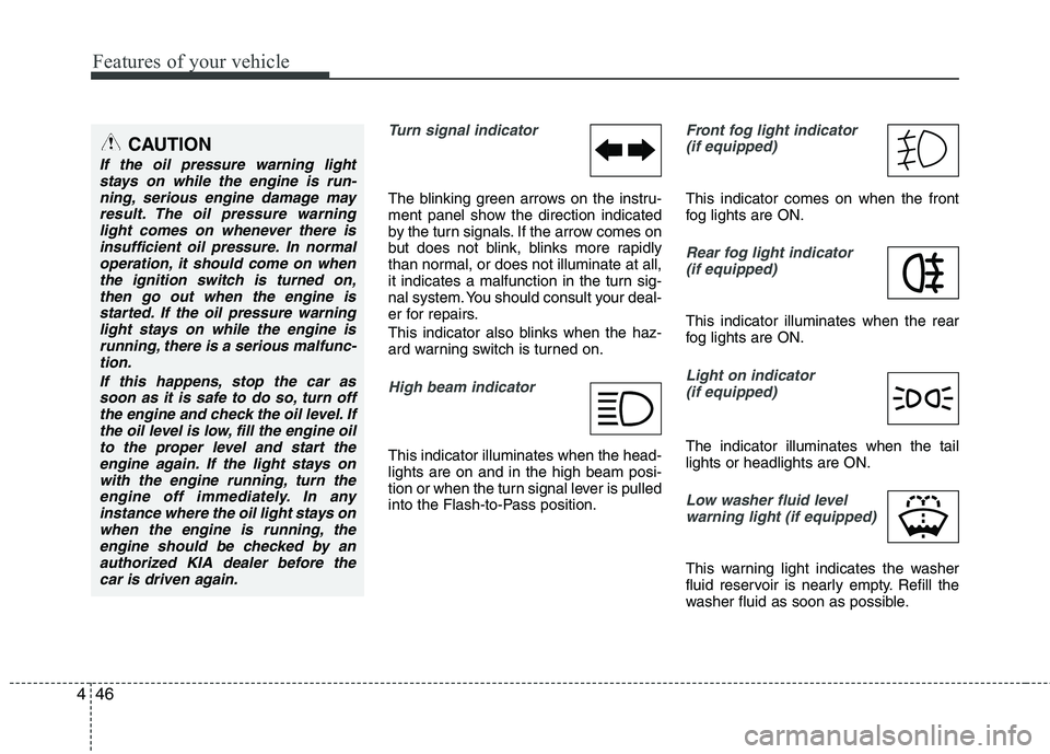
Turn signal indicator
The blinking green arrows on the instru-
ment panel show the direction indicated
by the turn signals. If the arrow comes on
but does not blink, blinks more rapidly
than normal, or does not illuminate at all,
it indicates a malfunction in the turn sig-
nal system. You should consult your deal-
er for repairs.
This indicator also blinks when the haz-
ard warning switch is turned on.
High beam indicator
This indicator illuminates when the head- lights are on and in the high beam posi-
tion or when the turn signal lever is pulled
into the Flash-to-Pass position.
Front fog light indicator
(if equipped)
This indicator comes on when the front
fog lights are ON.
Rear fog light indicator
(if equipped)
This indicator illuminates when the rear
fog lights are ON.
Light on indicator (if equipped)
The indicator illuminates when the tail lights or headlights are ON.
Low washer fluid levelwarning light (if equipped)
This warning light indicates the washer
fluid reservoir is nearly empty. Refill the
washer fluid as soon as possible.
CAUTION
If the oil pressure warning lightstays on while the engine is run-
ning, serious engine damage mayresult. The oil pressure warninglight comes on whenever there is insufficient oil pressure. In normal
operation, it should come on whenthe ignition switch is turned on,then go out when the engine is
started. If the oil pressure warninglight stays on while the engine isrunning, there is a serious malfunc-tion.
If this happens, stop the car assoon as it is safe to do so, turn off the engine and check the oil level. Ifthe oil level is low, fill the engine oilto the proper level and start the
engine again. If the light stays onwith the engine running, turn theengine off immediately. In any instance where the oil light stays on
when the engine is running, theengine should be checked by an authorized KIA dealer before thecar is driven again.
Page 128 of 442
457
Features of your vehicle
✽✽NOTICE
This system can only sense objects with-
in the range and location of the sensors;
It can not detect objects in other areas
where sensors are not installed. Also,
small or slim objects, such as poles or
objects located between sensors may not
be detected by the sensors.
Always visually check behind the vehi-
cle when backing up.
Be sure to inform any drivers of the
vehicle that may be unfamiliar with the
system regarding the systems capabili-
ties and limitations.Self-diagnosis
If you don’t hear an audible warning
sound or if the buzzer sounds intermit-tently when shifting the gear to the R
(Reverse) position, this may indicate a
malfunction in the rear parking assist sys-
tem. If this occurs, have your vehicle
checked by an authorized KIA dealer as
soon as possible.
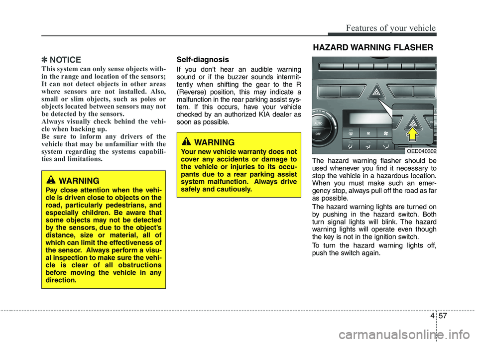
The hazard warning flasher should be
used whenever you find it necessary to
stop the vehicle in a hazardous location.
When you must make such an emer-
gency stop, always pull off the road as far
as possible.
The hazard warning lights are turned on
by pushing in the hazard switch. Both
turn signal lights will blink. The hazard
warning lights will operate even though
the key is not in the ignition switch.
To turn the hazard warning lights off,
push the switch again.
WARNING
Pay close attention when the vehi-
cle is driven close to objects on the
road, particularly pedestrians, and
especially children. Be aware that
some objects may not be detected
by the sensors, due to the object’s
distance, size or material, all of
which can limit the effectiveness of
the sensor. Always perform a visu-al inspection to make sure the vehi-
cle is clear of all obstructions
before moving the vehicle in anydirection.
WARNING
Your new vehicle warranty does not
cover any accidents or damage to
the vehicle or injuries to its occu-pants due to a rear parking assist
system malfunction. Always drive
safely and cautiously.
HAZARD WARNING FLASHER
OED040302
Page 131 of 442
Features of your vehicle
60
4
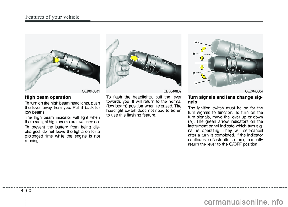
High beam operation
To turn on the high beam headlights, push
the lever away from you. Pull it back for
low beams. The high beam indicator will light when
the headlight high beams are switched on.
To prevent the battery from being dis-
charged, do not leave the lights on for aprolonged time while the engine is not
running. To flash the headlights, pull the lever
towards you. It will return to the normal
(low beam) position when released. The
headlight switch does not need to be on
to use this flashing feature.
Turn signals and lane change sig- nals
The ignition switch must be on for the
turn signals to function. To turn on the
turn signals, move the lever up or down
(A). The green arrow indicators on the
instrument panel indicate which turn sig-
nal is operating. They will self-cancel
after a turn is completed. If the indicator
continues to flash after a turn, manually
return the lever to the O/OFF position.
OED040802OED040801OED040804
Page 132 of 442
461
Features of your vehicle
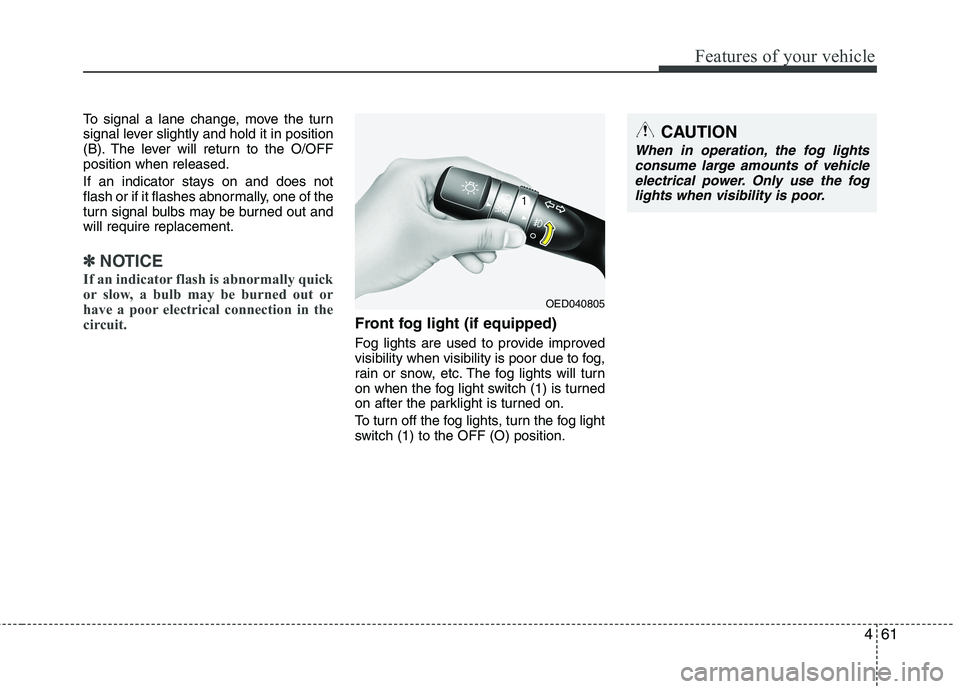
To signal a lane change, move the turn
signal lever slightly and hold it in position
(B). The lever will return to the O/OFFposition when released.
If an indicator stays on and does not
flash or if it flashes abnormally, one of the
turn signal bulbs may be burned out andwill require replacement.
✽✽NOTICE
If an indicator flash is abnormally quick
or slow, a bulb may be burned out or
have a poor electrical connection in the
circuit.
Front fog light (if equipped)
Fog lights are used to provide improved
visibility when visibility is poor due to fog,
rain or snow, etc. The fog lights will turn
on when the fog light switch (1) is turned
on after the parklight is turned on.
To turn off the fog lights, turn the fog light
switch (1) to the OFF (O) position.
OED040805
CAUTION
When in operation, the fog lights consume large amounts of vehicle
electrical power. Only use the fog lights when visibility is poor.
Page 175 of 442
Features of your vehicle
104
4
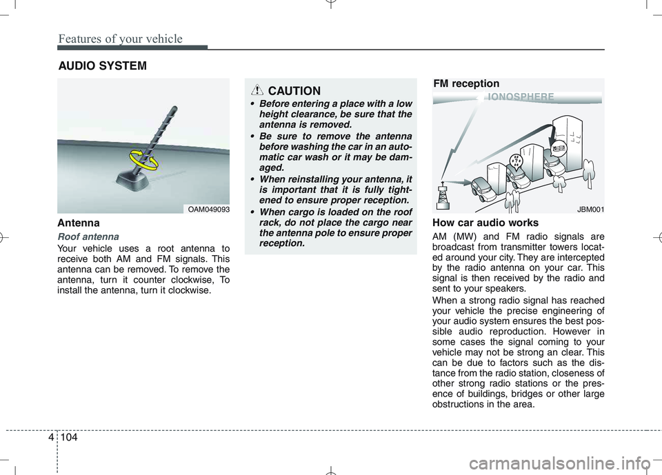
Antenna
Roof antenna
Your vehicle uses a root antenna to
receive both AM and FM signals. This
antenna can be removed. To remove the
antenna, turn it counter clockwise, To
install the antenna, turn it clockwise. How car audio works
AM (MW) and FM radio signals are
broadcast from transmitter towers locat-
ed around your city. They are intercepted
by the radio antenna on your car. This
signal is then received by the radio and
sent to your speakers.
When a strong radio signal has reached
your vehicle the precise engineering of
your audio system ensures the best pos-
sible audio reproduction. However in
some cases the signal coming to your
vehicle may not be strong an clear. This
can be due to factors such as the dis-
tance from the radio station, closeness of
other strong radio stations or the pres-
ence of buildings, bridges or other large
obstructions in the area.
AUDIO SYSTEM
OAM049093
CAUTION
• Before entering a place with a low
height clearance, be sure that the
antenna is removed.
Be sure to remove the antenna before washing the car in an auto-matic car wash or it may be dam-
aged.
When reinstalling your antenna, it is important that it is fully tight-ened to ensure proper reception.
When cargo is loaded on the roof rack, do not place the cargo near
the antenna pole to ensure properreception.
JBM001
FM reception