stop start KIA CEED 2014 Owners Manual
[x] Cancel search | Manufacturer: KIA, Model Year: 2014, Model line: CEED, Model: KIA CEED 2014Pages: 1206, PDF Size: 50.15 MB
Page 1023 of 1206
Driving your vehicle
74
5
Turn signals when towing a trailer
When you tow a trailer, your vehicle has
to have a different turn signal flasher and
extra wiring. The green arrows on your
instrument panel will flash whenever you
signal a turn or lane change. Properly
connected, the trailer lights will also flash
to alert other drivers you’re about to turn,
change lanes, or stop.
When towing a trailer, the green arrows
on your instrument panel will flash for
turns even if the bulbs on the trailer are
burned out. Thus, you may think drivers
behind you are seeing your signals
when, in fact, they are not. It is important
to check occasionally to be sure the trail-
er bulbs are still working. You must also
check the lights every time you discon-
nect and then reconnect the wires.
Do not connect a trailer lighting system
directly to your vehicle’s lighting system.
Use only an approved trailer wiring har-
ness.
An authorised Kia dealer can assist you
in installing the wiring harness.
Driving on grades
Reduce speed and shift to a lower gear
before you start down a long or steep
downgrade. If you don’t shift down, you
might have to use your brakes so much
that they would get hot and no longer
operate efficiently.
On a long uphill grade, shift down and
reduce your speed to around 70 km/h (45mph) to reduce the possibility of engine
and transaxle overheating.
If your trailer weighs more than the max-
imum trailer weight without trailer brakes
and you have an automatic transaxle,
you should drive in D (Drive) when tow-
ing a trailer.
Operating your vehicle in D (Drive) when
towing a trailer will minimize heat build up
and extend the life of your transaxle.
WARNING
Failure to use an approved trailer wiring harness could result in dam-
age to the vehicle electrical system
and/or personal injury.
CAUTION
When towing a trailer on steep grades (in excess of 6%) pay close
attention to the engine coolant temperature gauge to ensure theengine does not overheat.
If the coolant temperature redwarning light illuminates or the coolant temperature gauge movestowards “130”, pull over and stop as soon as it is safe to do so, and
allow the engine to idle until it cools down. You may proceed oncethe engine has cooled sufficiently.
You must decide driving speed depending on trailer weight anduphill grade to reduce the possi- bility of engine and transaxleoverheating.
JD RHD 5.QXP 4/29/2013 11:28 AM Page 74
Page 1025 of 1206
Driving your vehicle
76
5
When you are ready to leave after park- ing on a hill
1. With the manual transaxle in Neutral
or automatic transaxle in P (Park),
apply your brakes and hold the brake
pedal down whilst you:
Start your engine;
Shift into gear; and
Release the parking brake.
2. Slowly remove your foot from the brake pedal.
3. Drive slowly until the trailer is clear of the chocks.
4. Stop and have someone pick up and store the chocks. Maintenance when trailer towing
Your vehicle will need service more often
when you regularly pull a trailer.
Important items to pay particular atten-tion to include engine oil, automatic
transaxle fluid, axle lubricant and cooling
system fluid. Brake condition is another
important item to frequently check. Each
item is covered in this manual, and the
Index will help you find them quickly. If
you’re trailering, it is a good idea to
review these sections before you start
your trip.
Do not forget to also maintain your trailer
and towbar hitch. Follow the mainte-
nance schedule that accompanied your
trailer and check it periodically.
Preferably, conduct the check at the start
of each day’s driving. Most importantly,
all towbar hitch nuts and bolts should betight.CAUTION
Due to higher load during trailer
usage, overheating might occur
in hot days or during uphill driv-ing. If the coolant gauge indicatesover-heating, switch off the air conditioner and stop the vehicle
in a safe area to cool down the engine.
When towing check transaxle fluid more frequently.
If your vehicle is not equipped with an air conditioner, youshould install a condenser fan to improve engine performance
when towing a trailer.
JD RHD 5.QXP 4/29/2013 11:28 AM Page 76
Page 1032 of 1206
63
What to do in an emergency
IN CASE OF AN EMERGENCY WHILST DRIVING
If the engine stalls at a crossroad
or crossing
If the engine stalls at a crossroad or crossing, set the shift lever in the N
(Neutral) position and then push the
vehicle to a safe place.
If your vehicle has a manual transaxle not equipped with a ignition lock
switch, the vehicle can move forward
by shifting to the 2(Second) or 3(Third)
gear and then turning the starter with-out depressing the clutch pedal. If you have a flat tyre whilst driv- ing
If a tyre goes flat whilst you are driving:
1. Take your foot off the accelerator pedal
and let the vehicle slow down whilst
driving straight ahead. Do not apply the
brakes immediately or attempt to pull
off the road as this may cause a loss of
control. When the vehicle has slowed
to such a speed that it is safe to do so,
brake carefully and pull off the road.
Drive off the road as far as possible
and park on firm, level ground. If you
are on a divided highway, do not park
in the median area between the two
traffic lanes.
2. When the vehicle is stopped, turn on your emergency hazard flashers, set
the parking brake and put the transaxle
in P (automatic transaxle) or reverse
(manual transaxle).
3. Have all passengers get out of the vehicle. Be sure they all get out on the
side of the vehicle that is away from
traffic.
4. When changing a flat tyre, follow the instruction provided later in this sec-tion. If engine stalls whilst driving
1. Reduce your speed gradually, keeping
a straight line. Move cautiously off the
road to a safe place.
2. Turn on your emergency flashers.
3. Try to start the engine again. If your vehicle does not start, we recommend
that you consult an authorised Kia
dealer.
JD RHD 6.QXP 4/29/2013 11:30 AM Page 3
Page 1052 of 1206
623
What to do in an emergency
TYRE PRESSURE MONITORING SYSTEM (TPMS) (IF EQUIPPED)
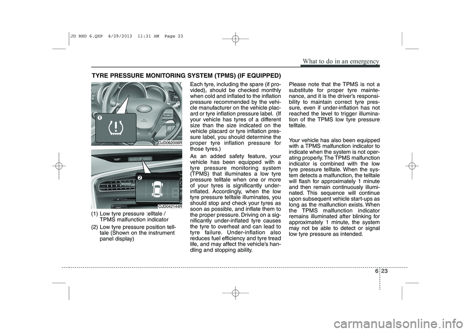
(1) Low tyre pressure telltale / TPMS malfunction indicator
(2) Low tyre pressure position tell- tale (Shown on the instrument
panel display) Each tyre, including the spare (if pro-
vided), should be checked monthlywhen cold and inflated to the inflation
pressure recommended by the vehi-
cle manufacturer on the vehicle plac-
ard or tyre inflation pressure label. (If
your vehicle has tyres of a different
size than the size indicated on the
vehicle placard or tyre inflation pres-
sure label, you should determine the
proper tyre inflation pressure for
those tyres.)
As an added safety feature, your
vehicle has been equipped with a
tyre pressure monitoring system
(TPMS) that illuminates a low tyrepressure telltale when one or more
of your tyres is significantly under-
inflated. Accordingly, when the low
tyre pressure telltale illuminates, you
should stop and check your tyres as
soon as possible, and inflate them to
the proper pressure. Driving on a sig-nificantly under-inflated tyre causes
the tyre to overheat and can lead to
tyre failure. Under-inflation alsoreduces fuel efficiency and tyre tread
life, and may affect the vehicle’s han-
dling and stopping ability. Please note that the TPMS is not a
substitute for proper tyre mainte-
nance, and it is the driver’s responsi-bility to maintain correct tyre pres-
sure, even if under-inflation has not
reached the level to trigger illumina-
tion of the TPMS low tyre pressure
telltale.
Your vehicle has also been equipped
with a TPMS malfunction indicator toindicate when the system is not oper-
ating properly. The TPMS malfunction
indicator is combined with the low
tyre pressure telltale. When the sys-tem detects a malfunction, the telltale
will flash for approximately 1 minute
and then remain continuously illumi-
nated. This sequence will continue
upon subsequent vehicle start-ups as
long as the malfunction exists. When
the TPMS malfunction indicator
remains illuminated after blinking for
approximately 1 minute, the system
may not be able to detect or signal
low tyre pressure as intended.
OJD062006R
OJD042144R
JD RHD 6.QXP 4/29/2013 11:31 AM Page 23
Page 1068 of 1206
77
Maintenance
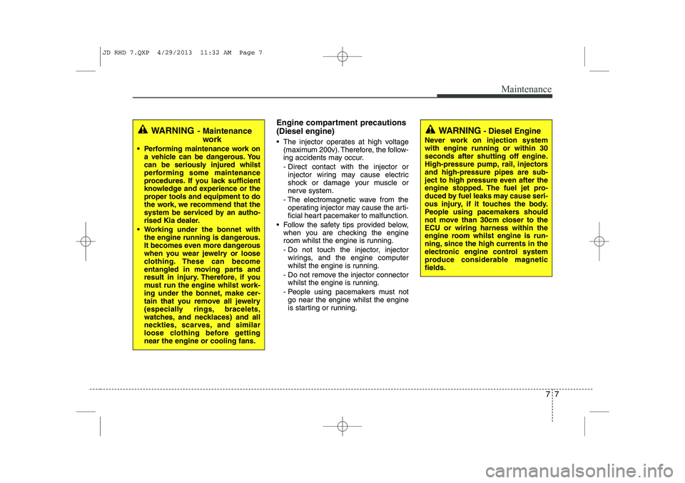
Engine compartment precautions (Diesel engine)
• The injector operates at high voltage(maximum 200v). Therefore, the follow-
ing accidents may occur.
- Direct contact with the injector or
injector wiring may cause electric
shock or damage your muscle or
nerve system.
- The electromagnetic wave from the operating injector may cause the arti-
ficial heart pacemaker to malfunction.
Follow the safety tips provided below, when you are checking the engine
room whilst the engine is running.
- Do not touch the injector, injector
wirings, and the engine computer
whilst the engine is running.
- Do not remove the injector connector whilst the engine is running.
- People using pacemakers must not go near the engine whilst the engine
is starting or running.
WARNING - Maintenance
work
Performing maintenance work on a vehicle can be dangerous. You
can be seriously injured whilst
performing some maintenance
procedures. If you lack sufficient
knowledge and experience or the
proper tools and equipment to do
the work, we recommend that the
system be serviced by an autho-
rised Kia dealer.
Working under the bonnet with the engine running is dangerous.
It becomes even more dangerous
when you wear jewelry or loose
clothing. These can become
entangled in moving parts and
result in injury. Therefore, if you
must run the engine whilst work-
ing under the bonnet, make cer-
tain that you remove all jewelry
(especially rings, bracelets,
watches, and necklaces) and all
neckties, scarves, and similar
loose clothing before gettingnear the engine or cooling fans.WARNING - Diesel Engine
Never work on injection system with engine running or within 30
seconds after shutting off engine.
High-pressure pump, rail, injectorsand high-pressure pipes are sub-
ject to high pressure even after the
engine stopped. The fuel jet pro-
duced by fuel leaks may cause seri-
ous injury, if it touches the body.
People using pacemakers should
not move than 30cm closer to theECU or wiring harness within the
engine room whilst engine is run-
ning, since the high currents in the
electronic engine control system
produce considerable magneticfields.
JD RHD 7.QXP 4/29/2013 11:32 AM Page 7
Page 1095 of 1206
Maintenance
34
7
EXPLANATION OF SCHEDULED MAINTENANCE ITEMS
Engine oil and filter The engine oil and filter should be
changed at the intervals specified in the
maintenance schedule. If the car is being
driven in severe conditions, more fre-quent oil and filter changes are required. Drive belts
Inspect all drive belts for evidence of cuts,
cracks, excessive wear or oil saturation
and replace if necessary. Drive belts
should be checked periodically for proper
tension and adjusted as necessary.
Fuel filter (cartridge) A clogged filter can limit the speed at
which the vehicle may be driven, damage
the emission system and cause multiple
issues such as hard starting. If an exces-
sive amount of foreign matter accumu-
lates in the fuel tank, the filter may
require replacement more frequently.
After installing a new filter, run the engine
for several minutes, and check for leaks
at the connections. We recommend that
the fuel filter be replaced by an autho-
rised Kia dealer. Fuel lines, fuel hoses and con- nections
Check the fuel lines, fuel hoses and con-
nections for leakage and damage. We
recommend that the fuel lines, fuel hoses
and connections be replaced by an
authorised Kia dealer.
Vapour hose and fuel filler cap
The vapour hose and fuel filler cap
should be inspected at those intervals
specified in the maintenance schedule.
Make sure that a new vapour hose or fuelfiller cap is correctly replaced.
Vacuum crankcase ventilation hoses (if equipped)
Inspect the surface of hoses for evidence
of heat and/or mechanical damage. Hard
and brittle rubber, cracking, tears, cuts,
abrasions, and excessive swelling indi-
cate deterioration. Particular attention
should be paid to examine those hose
surfaces nearest to high heat sources,
such as the exhaust manifold. Inspect the hose routing to assure that the hoses do not come in contact with
any heat source, sharp edges or movingcomponent which might cause heat dam-
age or mechanical wear. Inspect all hose
connections, such as clamps and cou-
plings, to make sure they are secure, and
that no leaks are present. Hoses should
be replaced immediately if there is any
evidence of deterioration or damage.
WARNING -
Diesel only
Never work on injection system with engine running or within 30
seconds after shutting off engine.
High pressure pump, rail, injectorsand high pressure pipes are sub-
ject to high pressure even after the
engine stopped. The fuel jet pro-
duced by fuel leaks may cause seri-
ous injury, if it touch the body.
People using pacemakers should
not move more than 30cm closer tothe ECU or wiring harness within
the engine room whilst engine is
running, since the high currents in
the Common Rail system produce
considerable magnetic fields.
JD RHD 7.QXP 4/29/2013 11:32 AM Page 34
Page 1134 of 1206

773
Maintenance
No.Fuse ratingSymbolFuse NameProtected component
147.5AA/CONCluster Ionizer, A/C Control Module, Blower Relay, PTC Relay
157.5AIG2IG2ICM Relay Box (Head Lamp Washer Relay), Rain Sensor, BCM, Electro Chromic Mirror,
Panorama Sunroof, Smart, Key Control Module, Passenger Seat Warmer Module,
Driver Seat Warmer Module
1610AHTD MIRRDriver/Passenger Outside Mirror, ECU, A/C Control Module
177.5AINTERIORLAMPGlove Box Lamp, Luggage Lamp, Vanity Lamp LH/RH, Room Lamp,
Overhead Console Lamp
187.5A2PDM 2Smart Key Control Module, Start/Stop Button Switch
197.5AB/HORNICM Relay Box (Burglar Alarm Horn Relay)
2020ASUNROOFPanorama Sunroof
2110AMODULE 2MODULE 2
Electric Parking Brake Module, DC-DC Convertor (With ISG),
Head Lamp Levelling Device Switch, A/C Control Module, Rear Parking Assist Sensor,
Smart Parking Assist Control Module, Head Lamp LH/RH, ATM Shift Lever IND.,
Centre Facia Switch, Crash Pad Lower Switch, Driver/Passenger Seat Warmer Module,
Driver IMS Module
2215AHTD STRGSteering Wheel Heater
2320AIG1IG1E/R Fuse & Relay Box (ECU4, B/UP LAMP, ABS3, TCU2 FUSE)
2425AFRTWIPERWiper Relay , ICM Relay Box (Rain Sensor Relay), Front Wiper Motor
JD RHD 7.QXP 4/29/2013 11:34 AM Page 73
Page 1135 of 1206

Maintenance
74
7
No.Fuse ratingSymbolFuse NameProtected component
257.5AMEMORY2MEMORY 2Immobiliser Module (W/O Smart Key)
267.5AMEMORY1MEMORY 1
Driver/Passenger Outside Mirror (Folding), Driver/Passenger Smart Key Outside Handle, Driver IMS Module, Centre Facia Switch, Instrument Cluster, T yre Pressure Monitoring
Module, BCM, A/C Control Module, ICM Relay Box (Outside Mirror Folding/Unfolding Relay),
Ignition Key ILL. & Door Warning Switch, Rear Parking Assist Switch,
Data Link Connector, Buzzer
2710ABRAKE
SWITCHBRAKE
SWITCHSmart Key Control Module, Stop Lamp Switch
287.5ACLUSTERCLUSTERInstrument Cluster, Digital Clock
297.5A1POWER
STEERINGEPS Unit
307.5ASPARESPARE-
317.5ASTARTStart Relay, ECU, Ignition Lock Switch, Transaxle Range Switch,
TCU, Smart Key Control Module
3215AMULTI
MEDIAMULTI MEDIAA/V & Navigation Head Unit (W/O ISG), Audio (W/O ISG),
DC-DC Convertor (With ISG), Digital Clock
3310ASPARESPARE-
3425A1PDM 1Smart Key Control Module
3515APOWER
OUTLET1P/OUTLET 1Front Power Outlet
JD RHD 7.QXP 4/29/2013 11:35 AM Page 74
Page 1146 of 1206

785
Maintenance
FuseFuse ratingSymbolFuse NameProtected component
MULTIFUSE
80A1POWER
STEERINGEPS Unit
60AB+1B+1Inner Fuse Panel, IPS1 (H/LAMP HI LH,H/LAMP LOW LH, FRT TURN LH, POSITION LAMP LH),
IPS2 (STATIC BENDING LAMP LH/RH, DRL LH/RH)
40A1ABS1ESC Control Module, ABS Control Module
40A2ABS2ESC Control Module, ABS Control Module, Multipurpose Check Connector
40AIG2IG2W/O Smart Key : Ignition Switch, START RELAYWith Smart Key : IG2 RELAY, START RELAY, INNER FUSE PANEL (Fuse No. - 14/24/22/15/10)
60AB+2B+2Inner Fuse Panel, IPS3 (H/LAMP HI RH,H/LAMP LOW RH, FRT TURN RH,
POSITION LAMP RH), IPS4 (FRT FOG LAMP LH/RH, REAR TURN LH/RH),
IPS5 (REAR FOG LAMP, INT TAIL LAMP)
FUSE
40ARR
HTDRR HTDRR HTD RELAY , RR HTD
40AIG1IG1W/O Smart Key : Ignition Switch
With Smart Key : IG1 RELAY, ACC RELAY, INNER FUSE PANEL ( Fuse No. - 38/36/21/37/
23/29/28, Fuse No. - 13/8/35)
30A1EPB1Electric Parking Brake Module
30A2EPB2Electric Parking Brake Module
50AC/FANC/FAN LO RELAY, C/FAN HI RELAY
15ADEICERICM Relay Box (Front Deicer Relay)
15ASTOP
LAMPSTOP LAMPStop Signal Electronic Relay, HAC RELAY
Engine compartment main fuse panel (for diesel engine)
JD RHD 7.QXP 4/29/2013 11:35 AM Page 85
Page 1148 of 1206

787
Maintenance
SymbolRelay NameType
LOCOOLING FAN LOW RELAYPLUG MICRO
HICOOLING FAN HIGH RELAYPLUG MICRO
ESSESS RELAYPLUG MICRO
BLOWER RELAYPLUG MICRO
RR
HTDREAR DEFOGGER RELAYPLUG MICRO
4 (IG2)IG2 RELAYPLUG MICRO
FRT WIPER RELAYPLUG MICRO
3 (IG1)IG1 RELAYPLUG MICRO
1START RELAYPLUG MICRO
2 (ACC)ACC RELAYPLUG MICRO
FUEL HEATER RELAYPLUG MINI
HACHAC RELAYPLUG MICRO
Fuse ratingSymbolFuse NameRelay Name
15ASPARESPARE-
15AHORNHORN RELAY
10A2ECU2Oil Level Sensor, Fuel
Pressure Control Valve
20ASPARESPARE-
10A9SENSOR2
E/R Fuse & Relay Box
(COOLING FAN LOW RELAY),Lambda Sensor (D4FB), Stop Lamp Switch
20A1ECU1ECU
10A8SENSOR1
DSL Box (PTC1 RELAY,
GLOW RELAY),
VGT Control Sensor,
Camshaft Position Sensor,
Electrical EGR Valve
JD RHD 7.QXP 4/29/2013 11:35 AM Page 87