KIA CERATO 2006 Owners Manual
Manufacturer: KIA, Model Year: 2006,
Model line: CERATO,
Model: KIA CERATO 2006
Pages: 315, PDF Size: 11.29 MB
KIA CERATO 2006 Owners Manual
CERATO 2006
KIA
KIA
https://www.carmanualsonline.info/img/2/57949/w960_57949-0.png
KIA CERATO 2006 Owners Manual
Trending: remove seats, remote start, maintenance reset, wheel torque, reset, service, climate control
Page 161 of 315
449
1 23456789
Driving your vehicle
Lane change signals ( )
To signal a lane change, move the
turn signal lever slightly and hold it in
position. The lever will return to theOFF position when released.
If an indicator stays on and does not
flash or if it flashes abnormally, one
of the turn signal bulbs may be
burned out and will require replace-ment.
✽✽
NOTICE
If an indicator flash is abnormally
quick or slow, bulb may be burned
out or have a poor electrical con-
nection in the circuit.Front fog light (if equipped)
Fog lights are used to provide
improved visibility and avoid acci-dents when visibility is poor due to
fog, rain or snow etc. The fog lights
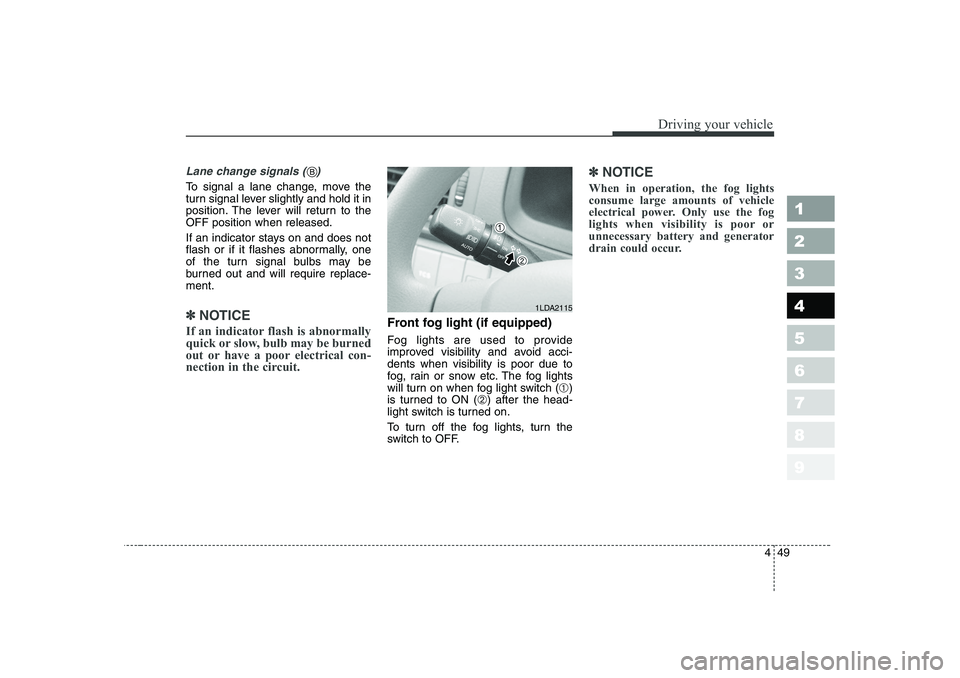
will turn on when fog light switch ( ➀)
is turned to ON ( ➁) after the head-
light switch is turned on.
To turn off the fog lights, turn the
switch to OFF.
✽✽
NOTICE
When in operation, the fog lights consume large amounts of vehicle
electrical power. Only use the fog
lights when visibility is poor orunnecessary battery and generator
drain could occur.
1LDA2115
B
Page 162 of 315
Driving your vehicle
50
4
1 23456789
Daytime running light (if equipped)
Daytime Running Lights (DRL) can
make it easier for others to see the
front of your vehicle during the day.
DRL can be helpful in many different
driving conditions, and it is especial-
ly helpful after dawn and before sun-set.
The DRL system will make your low-
beam headlights turn OFF when:
1. The headlight switch is ON.
2. The parklight switch is ON.
3. Engine stops. Headlight leveling device (if equipped)
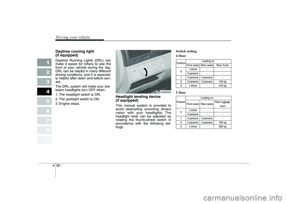
This manual system is provided to
avoid obstructing oncoming drivers
vision with your headlights. The
headlight level can be adjusted by
rotating the thumb-wheel switch in
accordance with the following set-
tings.Switch setting: 4 Door 5 Door
Position
Loading on
Front seats Rear seats Rear Trunk
0 1 driver - -
2 persons - -
1 2 persons 3 persons -
2 2 persons 3 persons 140 kg
3 1 driver - 410 kg
Loading on
Position Front seats Rear seats Rear luggage
room
0 1 driver - -
2 persons - -
1 2 persons 3 persons -
2 2 persons 3 persons 120 kg
3 1 driver - 380 kg
1LDE2201
Page 163 of 315
451
1 23456789
Driving your vehicle
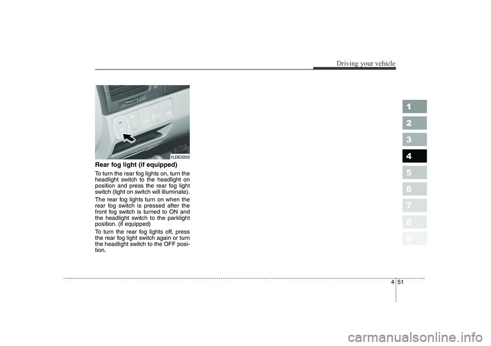
Rear fog light (if equipped)
To turn the rear fog lights on, turn the
headlight switch to the headlight on
position and press the rear fog light
switch (light on switch will illuminate).
The rear fog lights turn on when the
rear fog switch is pressed after the
front fog switch is turned to ON and
the headlight switch to the parklight
position. (if equipped)
To turn the rear fog lights off, press
the rear fog light switch again or turn
the headlight switch to the OFF posi-tion.
1LDE2202
Page 164 of 315
Driving your vehicle
52
4
1 23456789
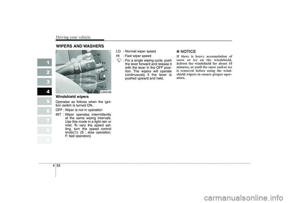
Windshield wipers
Operates as follows when the igni-
tion switch is turned ON.
OFF : Wiper is not in operation
INT : Wiper operates intermittently
at the same wiping intervals.
Use this mode in a light rain or
mist. To vary the speed set-
ting, turn the speed controlknob(➀). (S : slow operation,
F: fast operation) LO : Normal wiper speed
HI : Fast wiper speed
: For a single wiping cycle, pushthe lever forward and release it
with the lever in the OFF posi-
tion. The wipers will operate
continuously if the lever is
pushed upward and held.
✽✽ NOTICE
If there is heavy accumulation of
snow or ice on the windshield,
defrost the windshield for about 10
minutes, or until the snow and/or ice
is removed before using the wind-
shield wipers to ensure proper oper-ation.
WIPERS AND WASHERS
1LDA2108
Page 165 of 315
453
1 23456789
Driving your vehicle
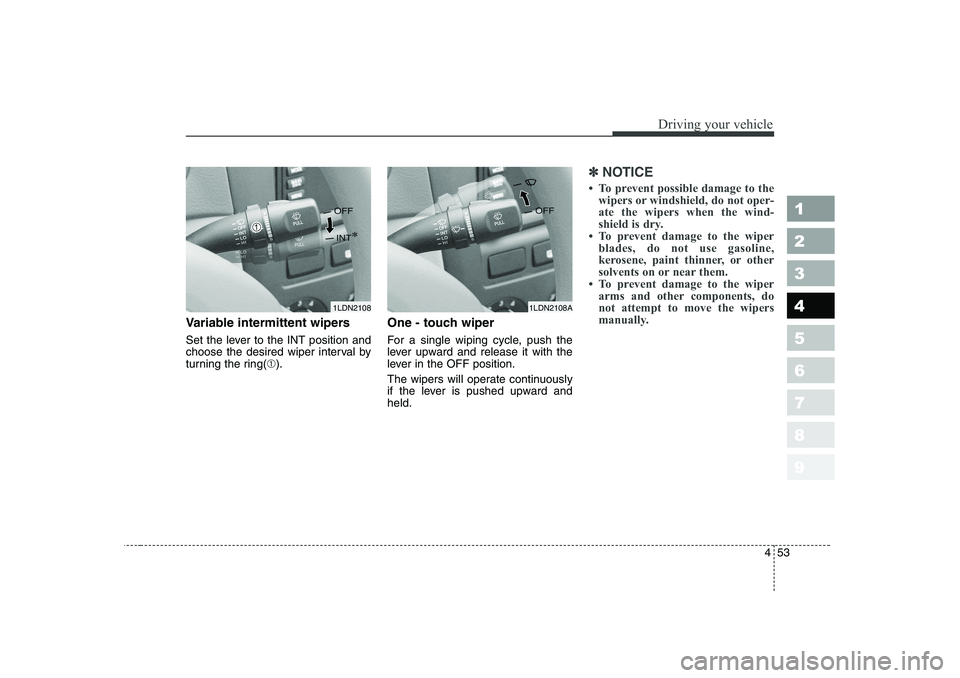
Variable intermittent wipers
Set the lever to the INT position and
choose the desired wiper interval by
turning the ring(➀). One - touch wiper
For a single wiping cycle, push the
lever upward and release it with the
lever in the OFF position.
The wipers will operate continuously
if the lever is pushed upward andheld.
✽✽
NOTICE
Page 166 of 315
Driving your vehicle
54
4
1 23456789
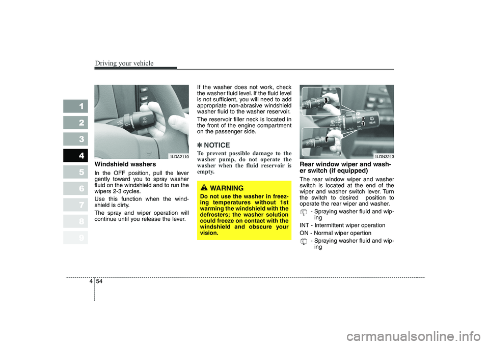
Windshield washers
In the OFF position, pull the lever
gently toward you to spray washer
fluid on the windshield and to run the
wipers 2-3 cycles. Use this function when the wind-
shield is dirty.
The spray and wiper operation will
continue until you release the lever. If the washer does not work, check
the washer fluid level. If the fluid level
is not sufficient, you will need to add
appropriate non-abrasive windshield
washer fluid to the washer reservoir.
The reservoir filler neck is located in
the front of the engine compartment
on the passenger side.
✽✽
NOTICE
To prevent possible damage to the
washer pump, do not operate the
washer when the fluid reservoir is
empty.
Rear window wiper and wash-
er switch (if equipped)
The rear window wiper and washer
switch is located at the end of the
wiper and washer switch lever. Turn
the switch to desired position to
operate the rear wiper and washer. - Spraying washer fluid and wip-ing
INT - Intermittent wiper operation
ON - Normal wiper opertion - Spraying washer fluid and wip-ing
1LDN32131LDA2110
WARNING
Do not use the washer in freez- ing temperatures without 1stwarming the windshield with the
defrosters; the washer solution
could freeze on contact with the
windshield and obscure yourvision.
Page 167 of 315
455
1 23456789
Driving your vehicle
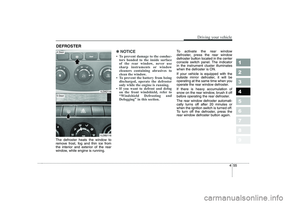
The defroster heats the window to
remove frost, fog and thin ice from
the interior and exterior of the rear
window, while engine is running.
✽✽NOTICE
Page 168 of 315
Driving your vehicle
56
4
1 23456789
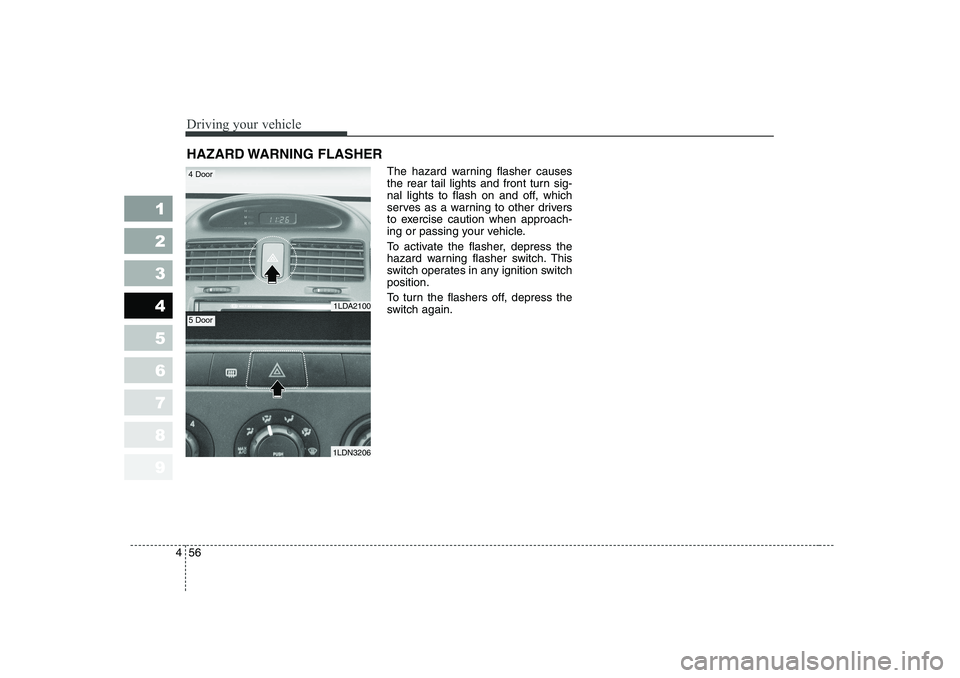
The hazard warning flasher causes
the rear tail lights and front turn sig-
nal lights to flash on and off, which
serves as a warning to other drivers
to exercise caution when approach-
ing or passing your vehicle.
To activate the flasher, depress the
hazard warning flasher switch. This
switch operates in any ignition switchposition.
To turn the flashers off, depress the
switch again.
HAZARD WARNING FLASHER
1LDA2100
1LDN3206
4 Door
5 Door
Page 169 of 315
457
1 23456789
Driving your vehicle
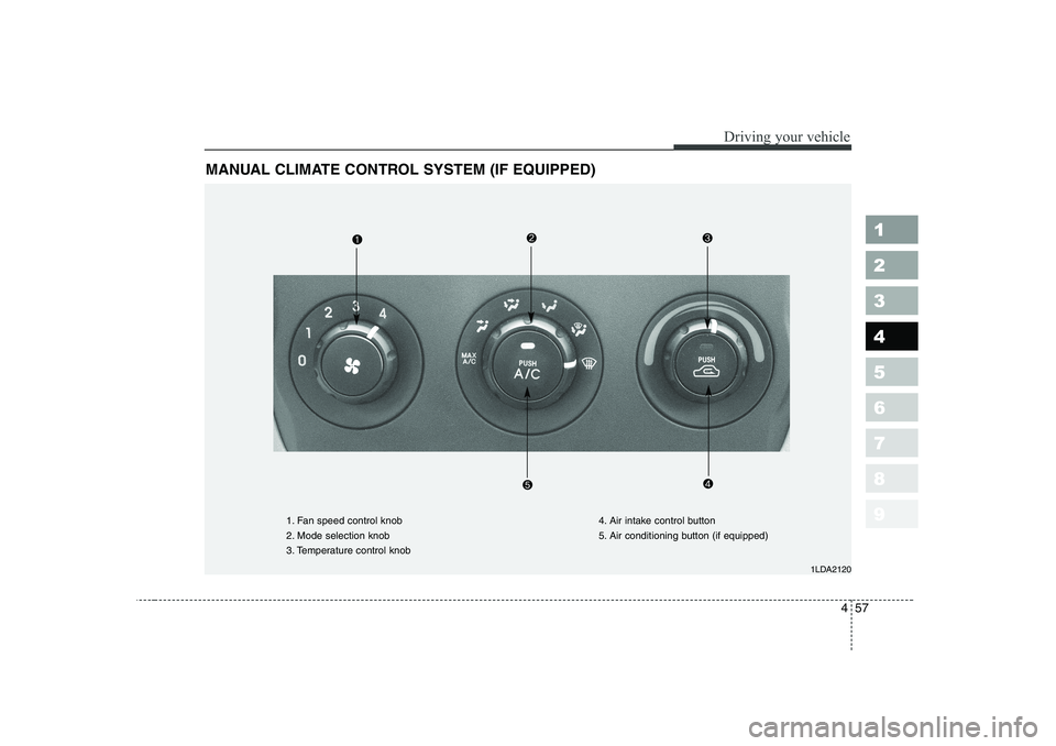
MANUAL CLIMATE CONTROL SYSTEM (IF EQUIPPED)
1LDA2120
1. Fan speed control knob
2. Mode selection knob
3. Temperature control knob4. Air intake control button
5. Air conditioning button (if equipped)
Page 170 of 315
Driving your vehicle
58
4
1 23456789
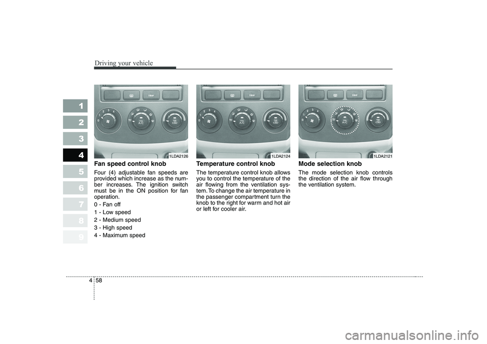
Fan speed control knob
Four (4) adjustable fan speeds are
provided which increase as the num-
ber increases. The ignition switch
must be in the ON position for fan
operation.
0 - Fan off
1 - Low speed2 - Medium speed3 - High speed
4 - Maximum speed Temperature control knob
The temperature control knob allows
you to control the temperature of the
air flowing from the ventilation sys-
tem. To change the air temperature in
the passenger compartment turn the
knob to the right for warm and hot air
or left for cooler air.
Mode selection knob The mode selection knob controls
the direction of the air flow through
the ventilation system.
1LDA21261LDA21241LDA2121
Trending: maintenance reset, battery capacity, heating, fuses, mirror, oil type, brake fluid


