ABS KIA CERATO 2008 Owners Manual
[x] Cancel search | Manufacturer: KIA, Model Year: 2008, Model line: CERATO, Model: KIA CERATO 2008Pages: 327, PDF Size: 42.19 MB
Page 62 of 327
Knowing your vehicle
52
3
1 23456789
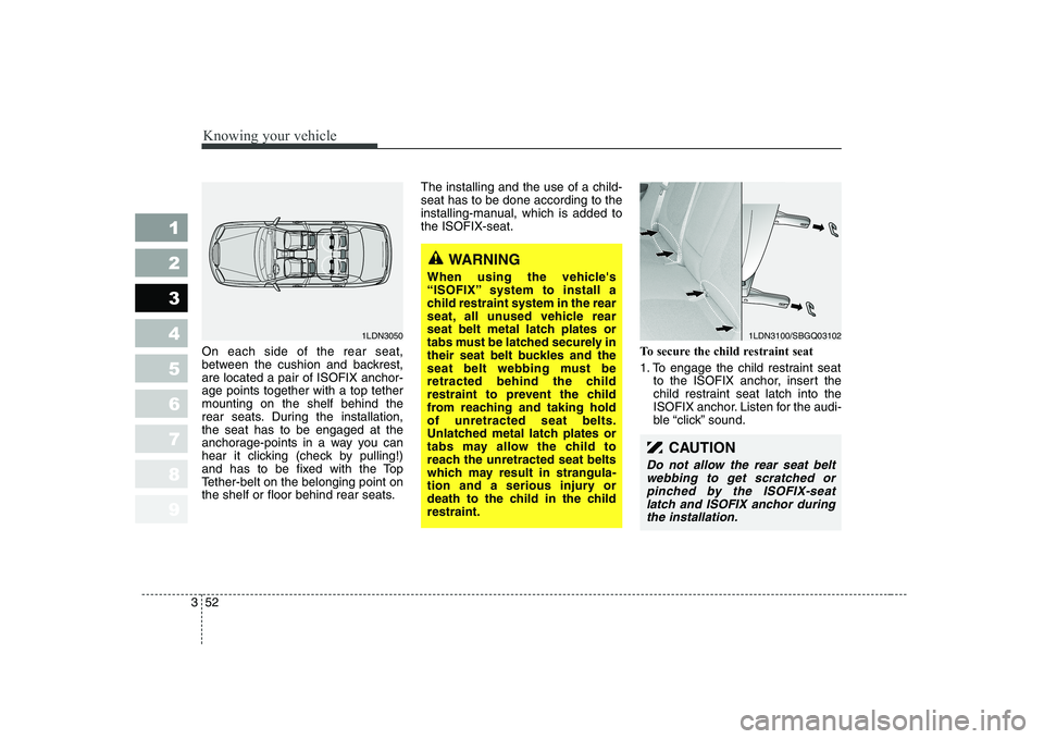
On each side of the rear seat,
between the cushion and backrest,are located a pair of ISOFIX anchor-age points together with a top tethermounting on the shelf behind the
rear seats. During the installation,the seat has to be engaged at the
anchorage-points in a way you can
hear it clicking (check by pulling!)
and has to be fixed with the Top
Tether-belt on the belonging point on
the shelf or floor behind rear seats. The installing and the use of a child-seat has to be done according to the
installing-manual, which is added tothe ISOFIX-seat.
To secure the child restraint seat
1. To engage the child restraint seatto the ISOFIX anchor, insert the
child restraint seat latch into the
ISOFIX anchor. Listen for the audi-
ble “click” sound.
1LDN3100/SBGQ03102
WARNING
When using the vehicle's
“ISOFIX” system to install a
child restraint system in the rear
seat, all unused vehicle rear
seat belt metal latch plates or
tabs must be latched securely in
their seat belt buckles and the
seat belt webbing must be
retracted behind the child
restraint to prevent the child
from reaching and taking holdof unretracted seat belts.
Unlatched metal latch plates or
tabs may allow the child to
reach the unretracted seat belts
which may result in strangula-
tion and a serious injury or
death to the child in the childrestraint.
1LDN3050
CAUTION
Do not allow the rear seat belt webbing to get scratched orpinched by the ISOFIX-seatlatch and ISOFIX anchor during the installation.
Page 75 of 327
365
1 23456789
Knowing your vehicle
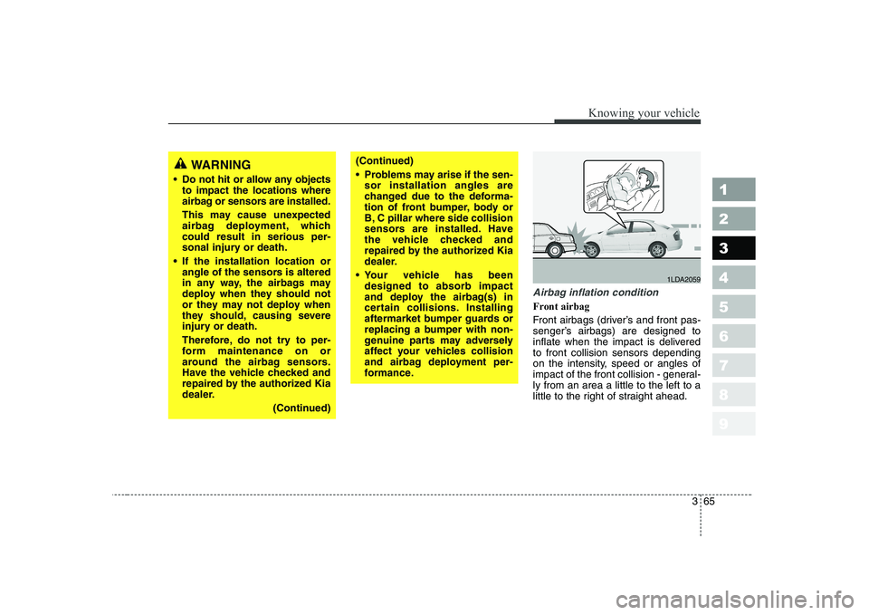
Airbag inflation condition
Front airbag
Front airbags (driver’s and front pas-
senger’s airbags) are designed to
inflate when the impact is deliveredto front collision sensors depending
on the intensity, speed or angles of
impact of the front collision - general-ly from an area a little to the left to a
little to the right of straight ahead.
WARNING
Do not hit or allow any objects to impact the locations where
airbag or sensors are installed.
This may cause unexpected
airbag deployment, whichcould result in serious per-
sonal injury or death.
If the installation location or angle of the sensors is altered
in any way, the airbags may
deploy when they should not
or they may not deploy when
they should, causing severe
injury or death.
Therefore, do not try to per-
form maintenance on or
around the airbag sensors.
Have the vehicle checked and
repaired by the authorized Kia
dealer.
(Continued)(Continued)
Problems may arise if the sen-sor installation angles are
changed due to the deforma-
tion of front bumper, body or
B, C pillar where side collision
sensors are installed. Have
the vehicle checked and
repaired by the authorized Kia
dealer.
Your vehicle has been designed to absorb impact
and deploy the airbag(s) in
certain collisions. Installing
aftermarket bumper guards or
replacing a bumper with non-
genuine parts may adversely
affect your vehicles collision
and airbag deployment per-
formance.
1LDA2059
Page 153 of 327
Driving your vehicle
18
4
1 23456789
Anti-lock brake system (ABS) (if equipped) The ABS system continuously sens-
es the speed of the wheels. If the
wheels are going to lock, the ABSsystem repeatedly modulates the
hydraulic brake pressure to the
wheels.
When you apply your brakes under
conditions which may lock the
wheels, you may hear a “tik-tik’’
sound from the brakes, or feel a cor-
responding sensation in the brake
pedal. This is normal and it means
your ABS system is active.
In order to obtain the maximum ben-
efit from your ABS system in anemergency situation, do not attempt
to modulate your brake pressure and
do not try to pump your brakes.
Press your brake pedal as hard as
possible or as hard as the situation
warrants and allow the ABS system
to control the force being delivered to
the brakes.
WARNING
- ABS Brakes
Your ABS is not a substitute for
good driving judgement. You
can still have an accident. In
fact, your ABS system will prob-
ably not be able to prevent an
accident in the following drivingconditions:
Dangerous driving, such as neglecting safety precautions,
speeding, or driving too close
to the vehicle in front of you.
Driving at high speed in situa- tions providing considerably
less traction, such as wet con-
ditions where hydroplaning
could occur.
(Continued)
(Continued)
Driving too fast on poor roadsurfaces. The ABS is
designed to improve maxi-
mum braking effectiveness on
typical highways and roads in
good condition. On poor roadsurfaces in poor condition,
the ABS may actually reduce
braking effectiveness.
Page 172 of 327
437
1 23456789
Driving your vehicle
Warning lights / audible indi-
cators
Checking operation
All warning lights are checked by
turning the ignition switch ON (do not
start the engine). Any light that does
not illuminate should be checked by
an Authorized Kia Dealer.
After starting the engine, check to
make sure that all warning lights are
off. If any are still on, this indicates a
situation that needs attention. When
releasing the parking brake, the
brake system warning light should go
off. The fuel warning light will stay on
if the fuel level is low.Anti-lock brake sys- tem (ABS) warninglight (if equipped)
This light illuminates if the key is
turned to ON and goes off in approx-imately 3 seconds if the system is
operating normally.
If the light stays on, you may have a
problem with your ABS system.
Contact an authorized Kia dealer as
soon as possible.
Electronic brake force
distribution (EBD)system warning light (if equipped)
If two warning lights illumi- nate at the same time
while driving, your vehicle
has a problem with ABSand EBD system.In this case, your ABS system and
regular brake system may not work
normally. Have the vehicle checked
by an Authorized Kia Dealer as soon
as possible.
WARNINGS AND INDICATORS
ABS
ABS
WARNING
If the both ABS and Brake warn-
ing lights are ON and stay ON,
your vehicle’s brake system will
not work normally. So you may
experience an unexpected and
dangerous situation during sud-
den braking. In this case, avoidhigh speed driving and abrupt
braking. Have your vehicle
checked by Authorized Kia
Dealer as soon as possible.
Page 222 of 327
Driving tips
8
5
1 23456789
SPECIAL DRIVING CONDITIONS
Hazardous driving conditions
When hazardous driving conditions
are encountered such as water,
snow, ice, mud, sand, or similar haz-
ards, follow these suggestions:
Drive cautiously and allow extra distance for braking.
Avoid sudden movements in brak- ing or steering.
When braking, pump the brake pedal with a light up-and-down
motion until the vehicle is stopped.
✽✽ NOTICE
Do not pump the brake pedal on a
vehicle equipped with ABS.
If stalled in snow, mud, or sand, use second gear. Accelerate slow-
ly to avoid spinning the drive
wheels.
Use sand, rock salt, tire chains, or other non-slip material under the
drive wheels to provide traction
when stalled in ice, snow, or mud. Rocking the vehicle
If it is necessary to rock the vehicle
to free it from snow, sand, or mud,
first turn the steering wheel right and
left to clear the area around your
front wheels. Then, shift back and
forth between 1 (First) and R
(Reverse) in vehicles equipped with
a manual transaxle or R (Reverse)
and any forward gear in vehiclesequipped with an automatic
transaxle. Do not race the engine,and spin the wheels as little as pos-
sible. If you are still stuck after a few
tries, have the vehicle pulled out by a
tow vehicle to avoid engine overheat-
ing and possible damage to the
transaxle.
✽✽
NOTICE
Prolonged rocking may cause engine
over-heating, transaxle damage or
failure, and tire damage.
WARNING - Downshifting
Downshifting with an automatic
transaxle, while driving on slip-
pery surfaces can cause an
accident. The sudden change intire speed could cause the tires
to skid. Be careful when down-
shifting on slippery surfaces.
Page 231 of 327
517
Driving tips
1 23456789
Safety chains
You should always attach chains
between your vehicle and your trail-
er. Cross the safety chains under the
tongue of the trailer so that thetongue will not drop to the road if it
becomes separated from the hitch.
Instructions about safety chains may
be provided by the hitch manufactur-
er or by the trailer manufacturer.
Follow the manufacturer’s recom-
mendation for attaching safety
chains. Always leave just enough
slack so you can turn with your trail-
er. And, never allow safety chains to
drag on the ground.
Trailer brakes
If your trailer weighs more than the
maximum trailer weight without trailer
brakes loaded, then it needs its own
brakes and they must be adequate.
Be sure to read and follow the
instructions for the trailer brakes so
you’ll be able to install, adjust and
maintain them properly.
Don’t tap into your vehicle's brake system.
Driving with a trailer
Towing a trailer requires a certain
amount of experience. Before setting
out for the open road, you must get
to know your trailer. Acquaint your-
self with the feel of handling and
braking with the added weight of the
trailer. And always keep in mind that
the vehicle you are driving is now a
good deal longer and not nearly so
responsive as your vehicle is by
itself.
Before you start, check the trailer
hitch and platform, safety chains,
electrical connector(s), lights, tires
and mirror adjustment. If the trailer
has electric brakes, start your vehicle
and trailer moving and then apply the
trailer brake controller by hand to be
sure the brakes are working. This lets
you check your electrical connection
at the same time.
During your trip, check occasionally
to be sure that the load is secure,
and that the lights and any trailer
brakes are still working.
WARNING
Do not use a trailer with its own
brakes unless you are absolute-
ly certain that you have properly
set up the brake system. This is
not a task for amateurs. Use an
experienced, competent trailer
shop for this work.
Page 234 of 327
Driving tips
20
5
1 23456789
Parking on hills
Generally, you should not park your
vehicle, with a trailer attached, on a
hill. People can be seriously or fatal-
ly injured, and both your vehicle and
the trailer can be damaged if they
begin a downhill trajectory. However, if you ever have to park
your trailer on a hill, here’s how to doit:
1. Apply your brakes, but don’t shift
into gear.
2. Have someone place chocks under the trailer wheels.
3. When the wheel chocks are in place, release the brakes until the
chocks absorb the load.
4. Reapply the brakes. Apply your parking brake, and then shift to R
(Reverse) for a manual transaxle
or P (Park) for an automatic
transaxle.
5. Release the brakes.
When you are ready to leave after parking on a hill
1. With the manual transaxle in Neutral or automatic transaxle in P
(Park), apply your brakes and hold
the brake pedal down while you:
and
2. Slowly remove your foot from the brake pedal.
3. Drive slowly until the trailer is clear of the chocks.
4. Stop and have someone pick up and store the chocks.
WARNING - Parking brake
It can be dangerous to get out of
your vehicle if the parking brake
is not firmly set.
If you have left the engine run-
ning, the vehicle can move sud-
denly. You or others could be
seriously or fatally injured.
WARNING - Parking on a
hill
Parking your vehicle on a hill
with a trailer attached could
cause serious injury or death,
should the trailer break lose.
Page 248 of 327
611
In case of an emergency
1 23456789
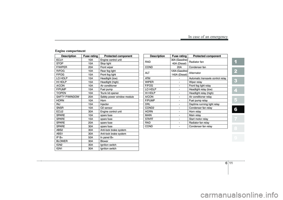
Description Fuse rating Protected component
ECU1 10A Engine control unit
STOP 15A Stop light
F/WIPER 20A Front wiper
R/FOG 10A Rear fog light
F/FOG 15A Front fog light
LO HDLP 15A Headlight (low)
HI HDLP 15A Headlight (high)
A/CON 10A Air conditioner
F/PUMP 15A Fuel pump
T/OPEN 10A Trunk lid opener
SAFTY P/WINDOW 20A Safety power window module
HORN 10A Horn
INJ 15A Injector
SNSR 10A O2 sensor
ECU2 30A Engine control unit
SPARE 10A spare fuse
SPARE 15A spare fuse
SPARE 20A spare fuse
SPARE 30A spare fuse
ABS2 30A Anti-lock brake system
ABS1 30A Anti-lock brake system
IP B+ 50A In panel B+
BLOWER 30A Blower
IGN2 30A Ignition switch
IGN1 30A Ignition switchDescription Fuse rating Protected component
RAD
30A (Gasoline)Radiator fan
40A (Diesel)
COND 20A Condenser fan
ALT
120A (Gasoline)Alternator
140A (Diesel)
ATM - Automatic transaxle control relay
WIPER - Wiper relay
F/FOG - Front fog light relay
LO HDLP - Headlight relay (low)
HI HDLP - Headlight relay (high)
A/CON - Air conditioner relay
F/PUMP - Fuel pump relay
DRL - Daytime running light relay
COND2 - Condenser fan relay
HORN - Horn relay
MAIN - Main relay
START - Start motor relay
RAD - Radiator fan relay
COND - Condenser fan relay
Engine compartment
Page 249 of 327
In case of an emergency
12
6
1 23456789
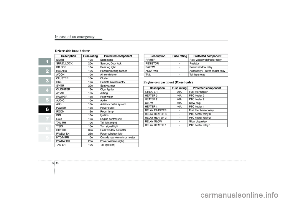
Driver-side knee bolster
Description Fuse rating Protected component
START 10A Start motor
SRF/D_LOCK 20A Sunroof, Door lock
RR FOG 10A Rear fog light
HAZARD 10A Hazard warning flasher
A/CON 10A Air conditioner
CLUSTER 10A Cluster
RKE 10A Remote keyless entry
S/HTR 20A Seat warmer
C/LIGHTER 15A Cigar lighter
A/BAG 15A Airbag
R/WIPER 15A Rear wiper
AUDIO 10A Audio
ABS 10A Anti-lock brake system
POWER 15A Power outlet
ROOM 15A Room lamp
IGN 10A Ignition
ECU 10A Engine control unit
TAIL RH 10A Tail light (right)
T/SIG 10A Turn signal light
RR/HTR 30A Rear window defroster
P/WDW LH 25A Power window (left)
HTD/MIRR 10A Outside rearview mirror heater
P/WDW RH 25A Power window (right)
TAIL LH 10A Tail light (left)Description Fuse rating Protected component
RR/HTR - Rear window defroster relay
RESISTOR - Resistor
P/WDW - Power window relay
ACC/PWR - Accessory / Power socket relay
TAIL - Tail light relay
Description Fuse rating Protected component
F/HEATER 30A Fuel filter heater
HEATER 3 40A PTC heater 3
HEATER 2 40A PTC heater 2
GLOW 60A Glow plug
HEATER 1 40A PTC heater 1
RELAY F/HEATER - Fuel filter heater relay
RELAY HEATER 3 - PTC heater relay 3
RELAY HEATER 2 - PTC heater relay 2
RELAY GLOW - Glow plug relay
RELAY HEATER 1 - PTC heater relay 1
Engine compartment (Diesel only)
Page 260 of 327
623
In case of an emergency
1 23456789
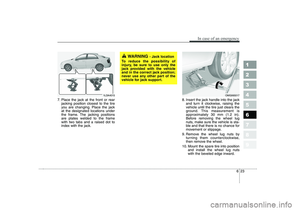
7. Place the jack at the front or rearjacking position closest to the tire
you are changing. Place the jackat the designated locations under
the frame. The jacking positions
are plates welded to the frame
with two tabs and a raised dot to
index with the jack. 8. Insert the jack handle into the jack
and turn it clockwise, raising the
vehicle until the tire just clears the
ground. This measurement is
approximately 30 mm (1.2 in).
Before removing the wheel lug
nuts, make sure the vehicle is sta-
ble and that there is no chance for
movement or slippage.
9. Remove the wheel lug nuts by turning them counterclockwise,
then remove the wheel.
10. Mount the spare tire into position and install the wheel lug nuts
with the beveled edge inward.
WARNING - Jack location
To reduce the possibility of
injury, be sure to use only the
jack provided with the vehicle
and in the correct jack position;
never use any other part of the
vehicle for jack support.
OMG0650171LDA4015