height KIA CERATO 2008 Owners Manual
[x] Cancel search | Manufacturer: KIA, Model Year: 2008, Model line: CERATO, Model: KIA CERATO 2008Pages: 327, PDF Size: 42.19 MB
Page 26 of 327
Knowing your vehicle
16
3
1 23456789
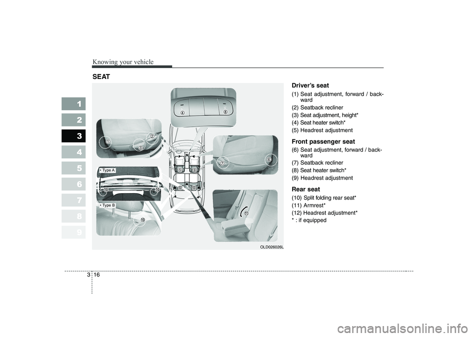
Driver’s seat
(1) Seat adjustment, forward / back-
ward
(2) Seatback recliner
(3) Seat adjustment, height*
(4) Seat heater switch*(5) Headrest adjustment
Front passenger seat
(6) Seat adjustment, forward / back- ward
(7) Seatback recliner (8)
Seat heater switch*
(9) Headrest adjustment Rear seat (10) Split folding rear seat*
(11) Armrest*
(12) Headrest adjustment*
* : if equipped
SEAT
OLD026026L
Page 28 of 327
Knowing your vehicle
18
3
1 23456789
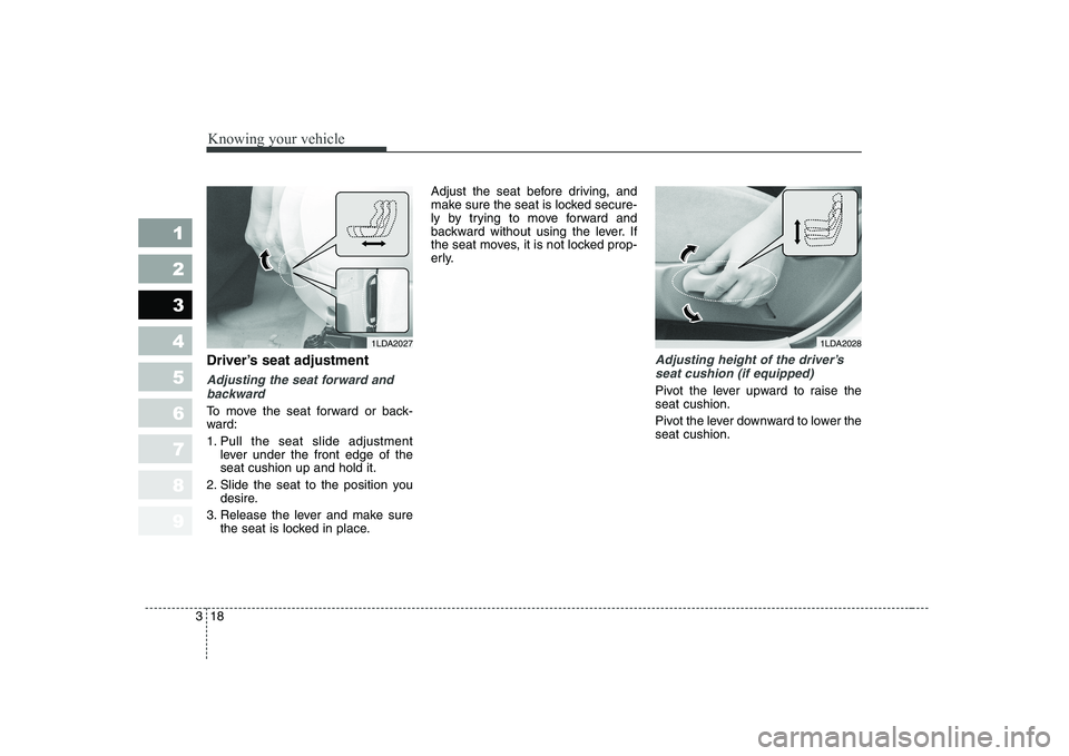
Driver’s seat adjustment
Adjusting the seat forward and
backward
To move the seat forward or back-
ward:
1. Pull the seat slide adjustment lever under the front edge of the seat cushion up and hold it.
2. Slide the seat to the position you desire.
3. Release the lever and make sure the seat is locked in place. Adjust the seat before driving, and
make sure the seat is locked secure-
ly by trying to move forward and
backward without using the lever. If
the seat moves, it is not locked prop-
erly.
Adjusting height of the driver’s
seat cushion (if equipped)
Pivot the lever upward to raise the seat cushion.
Pivot the lever downward to lower the seat cushion.
1LDA20271LDA2028
Page 31 of 327
321
1 23456789
Knowing your vehicle
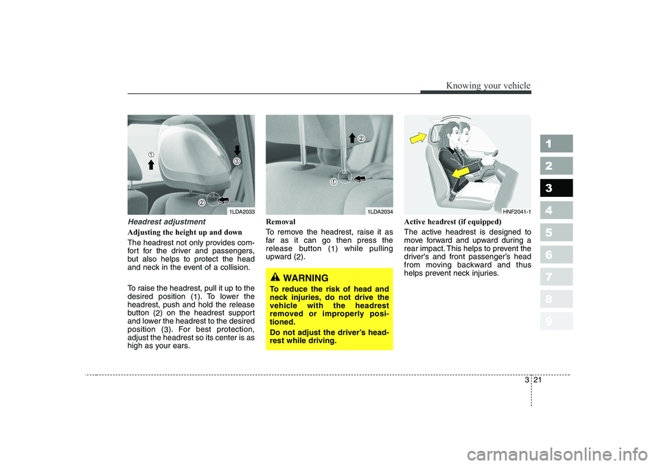
Headrest adjustment
Adjusting the height up and down
The headrest not only provides com-
fort for the driver and passengers,
but also helps to protect the head
and neck in the event of a collision.
To raise the headrest, pull it up to the desired position (1). To lower the
headrest, push and hold the release
button ( 2) on the headrest support
and lower the headrest to the desiredposition ( 3). For best protection,
adjust the headrest so its center is as
high as your ears. Removal
To remove the headrest, raise it as
far as it can go then press the
release button (
1) while pulling
upward ( 2). Active headrest (if equipped)
The active headrest is designed to
move forward and upward during a
rear impact. This helps to prevent the
driver's and front passenger’s head
from moving backward and thus
helps prevent neck injuries.
1LDA20331LDA2034
WARNING
To reduce the risk of head and
neck injuries, do not drive the
vehicle with the headrest
removed or improperly posi-tioned.
Do not adjust the driver’s head- rest while driving.
HNF2041-1
Page 35 of 327
325
1 23456789
Knowing your vehicle
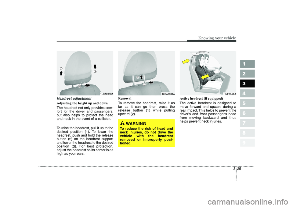
Headrest adjustment
Adjusting the height up and down
The headrest not only provides com-
fort for the driver and passengers,
but also helps to protect the head
and neck in the event of a collision.
To raise the headrest, pull it up to the desired position (1). To lower the
headrest, push and hold the release
button ( 2) on the headrest support
and lower the headrest to the desiredposition ( 3). For best protection,
adjust the headrest so its center is as
high as your ears. Removal
To remove the headrest, raise it as
far as it can go then press the
release button (
1) while pulling
upward ( 2). Active headrest (if equipped)
The active headrest is designed to
move forward and upward during a
rear impact. This helps to prevent the
driver's and front passenger’s head
from moving backward and thus
helps prevent neck injuries.
1LDA2033A1LDA2034A
WARNING
To reduce the risk of head and
neck injuries, do not drive the
vehicle with the headrest
removed or improperly posi-tioned.
HNF2041-1
Page 39 of 327
329
1 23456789
Knowing your vehicle
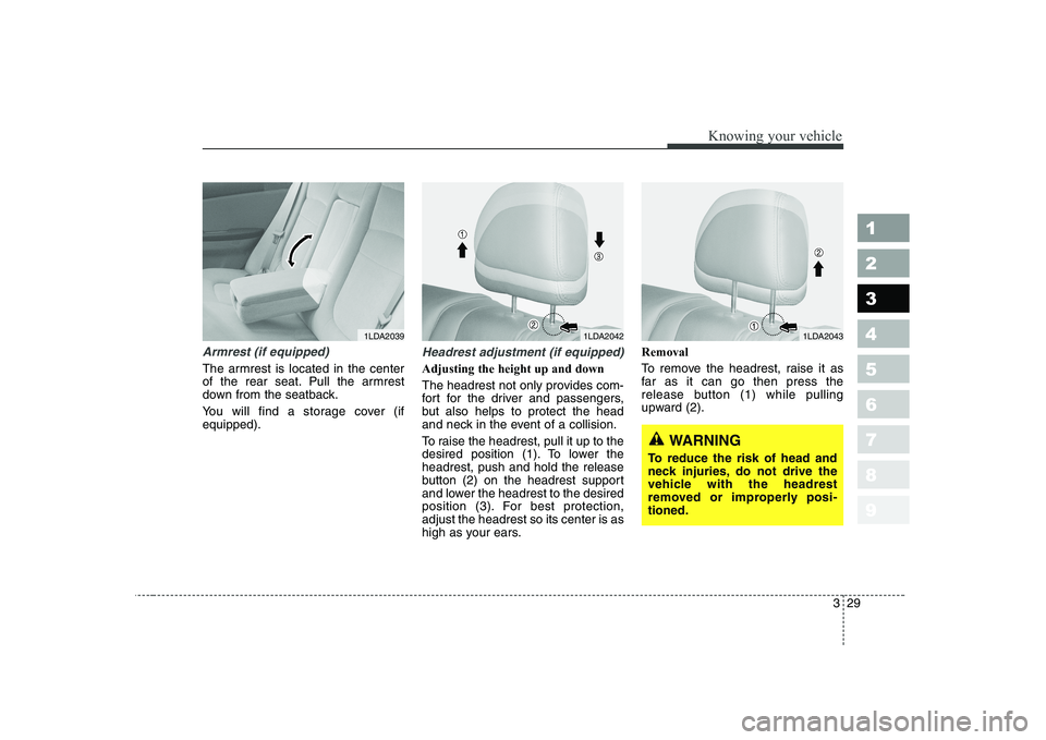
Armrest (if equipped)
The armrest is located in the center
of the rear seat. Pull the armrest
down from the seatback.
You will find a storage cover (if equipped).
Headrest adjustment (if equipped)
Adjusting the height up and down
The headrest not only provides com-
fort for the driver and passengers,
but also helps to protect the head
and neck in the event of a collision.
To raise the headrest, pull it up to the
desired position (1). To lower theheadrest, push and hold the release
button (2) on the headrest support
and lower the headrest to the desired
position (3). For best protection,adjust the headrest so its center is as
high as your ears.Removal
To remove the headrest, raise it as
far as it can go then press the
release button (1) while pulling
upward (2).
1LDA2042
WARNING
To reduce the risk of head and
neck injuries, do not drive the
vehicle with the headrest
removed or improperly posi-tioned.
1LDA20431LDA2039
Page 57 of 327
347
1 23456789
Knowing your vehicle
Installation on the rear seats(Continued)
Always make sure that theshoulder belt portion of the
outboard lap/shoulder belt is
positioned midway over the
shoulder, never across the
neck or behind the back.
Moving the child closer to the
center of the vehicle may help
provide a good shoulder belt
fit. The lap belt portion of thelap/shoulder belt or the center
seat lap belt must always be
positioned as low as possible
on the child's hips and as
snug as possible.
If the seat belt will not proper- ly fit the child, we recommend
the use of an approved boost-
er seat in the rear seat in order
to raise the child's seatingheight so that the seat belt will
properly fit the child.
(Continued)(Continued)
Never allow a child to stand upor kneel on the seat.
Never use an infant carrier or child safety seat that "hooks"
over a seatback; it may not
provide adequate security inan accident.
Never allow a child to be held in a person's arms while they
are in a moving vehicle, asthis could result in serious
injury to the child in the event
of an accident or a sudden
stop. Holding a child in a mov-
ing vehicle does not provide
the child with any means of
protection during an accident,
even if the person holding the
child is wearing a seat belt.
WARNING
Before installing the child restraint system, read the
instructions supplied by the
child restraint system manu-
facturer.
Failure to observe this manual instructions regarding childrestraint system and the
instructions provided with the
child restraint system could
increase the chance and/or
severity of injury in an acci-dent.
Page 88 of 327
Knowing your vehicle
78
3
1 23456789
Closing the hood
1. Before closing the hood, check the
following:
ment must be correctly installed.
bustible material must be
removed from the engine com-
partment.
2. Secure the support rod in its clip.
3. Lower the hood to about 30 cm (12 inches) height and then let it
drop to properly lock in place.
Make sure the hood is properly
locked before driving.WARNING
Before closing the hood, make sure that all engine parts and
tools have been removed fromthe engine area and that no
one’s hands are near the hoodopening.
Do not leave gloves, rags or any other combustible materi-
al in the engine compartment.
Doing so may cause a heat-
induced fire.
Page 111 of 327
3 101
1 23456789
Knowing your vehicle
Manual antenna (if equipped)
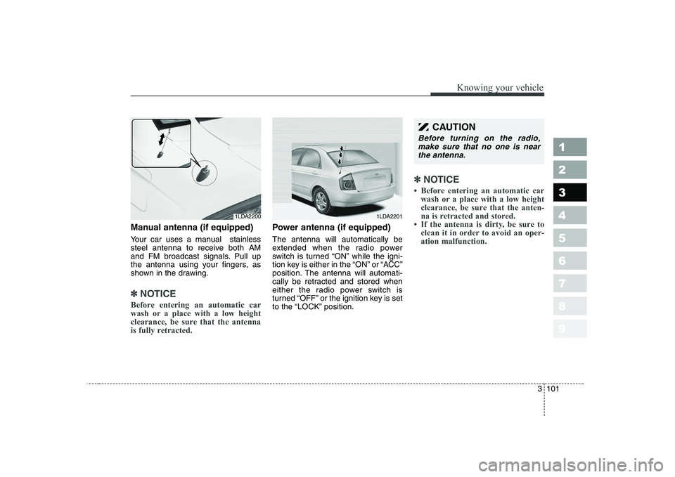
Your car uses a manual stainless
steel antenna to receive both AM
and FM broadcast signals. Pull up
the antenna using your fingers, as
shown in the drawing.
✽✽NOTICE
Before entering an automatic car
wash or a place with a low height
clearance, be sure that the antenna
is fully retracted.
Power antenna (if equipped) The antenna will automatically be
extended when the radio power
switch is turned “ON” while the igni-
tion key is either in the “ON” or “ACC”
position. The antenna will automati-
cally be retracted and stored when
either the radio power switch is
turned “OFF” or the ignition key is set
to the “LOCK” position.
✽✽ NOTICE
Page 303 of 327
Maintenance
40
7
1 23456789
Wheel replacement
When replacing the metal wheels for
any reason, make sure the new
wheels are equivalent to the original
factory units in diameter, rim widthand offset.WARNING
When replacing tires, never mix radial, bias-belted, and
bias-type tires. All four tires
should be of the same size,
design and construction. Use
only the tire sizes listed on the
Tire Label found below the
door striker on the driver’s
side. Make sure that all tires
and wheels are the same size
and have the same load-carry-
ing capacity. Use only tire andwheel combinations recom-
mended on the Tire Label or
by an Authorized Kia Dealer.
Failure to follow these precau-
tions can adversely affect the
safety and handling of your
vehicle.
(Continued)(Continued)
The use of any other tire sizeor type may seriously affect
ride, handling, ground clear-
ance, tire clearance, andspeedometer calibration.
Driving on worn-out tires is very hazardous and will
reduce braking effectiveness,
steering accuracy, and trac-tion.
It is best to replace all four tires at the same time. If that is
not possible, or necessary,
then replace the two front or
two rear tires as a pair.Replacing just one tire can
seriously affect your vehicle’shandling.
WARNING
A wheel that is not the correct
size may adversely affect wheel
and bearing life, braking and
stopping abilities, handling
characteristics, ground clear-
ance, body-to-tire clearance,
snow chain clearance,
speedometer calibration, head-
light aim and bumper height.
Page 304 of 327
741
Maintenance
1 23456789
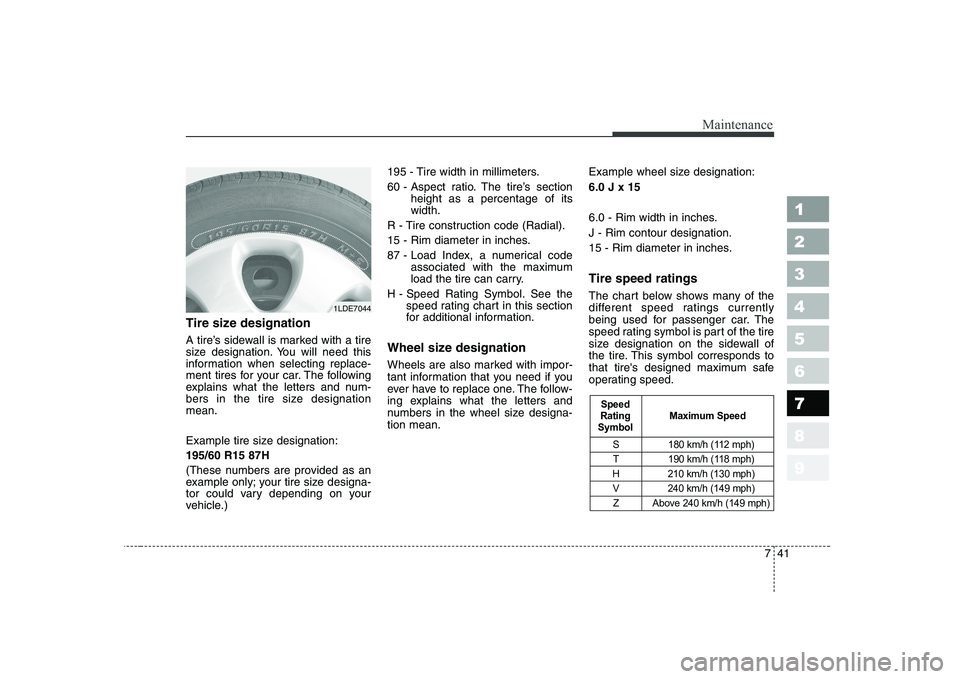
Tire size designation
A tire’s sidewall is marked with a tire
size designation. You will need this
information when selecting replace-
ment tires for your car. The following
explains what the letters and num-
bers in the tire size designationmean.
Example tire size designation: 195/60 R15 87H
(These numbers are provided as an
example only; your tire size designa-
tor could vary depending on your
vehicle.)195 - Tire width in millimeters.
60 - Aspect ratio. The tire’s section
height as a percentage of its width.
R - Tire construction code (Radial).
15 - Rim diameter in inches.
87 - Load Index, a numerical code associated with the maximum
load the tire can carry.
H - Speed Rating Symbol. See the speed rating chart in this section
for additional information.
Wheel size designation
Wheels are also marked with impor-
tant information that you need if you
ever have to replace one. The follow-
ing explains what the letters and
numbers in the wheel size designa-tion mean. Example wheel size designation: 6.0 J x 15
6.0 - Rim width in inches. J - Rim contour designation.
15 - Rim diameter in inches. Tire speed ratings
The chart below shows many of the
different speed ratings currently
being used for passenger car. The
speed rating symbol is part of the tire
size designation on the sidewall of
the tire. This symbol corresponds to
that tire's designed maximum safe
operating speed.
S 180 km/h (112 mph)
T 190 km/h (118 mph)
H 210 km/h (130 mph) V 240 km/h (149 mph)
Z Above 240 km/h (149 mph)
Maximum Speed
Speed
Rating
Symbol
1LDE7044