Button KIA Cerato 2014 2.G Owner's Manual
[x] Cancel search | Manufacturer: KIA, Model Year: 2014, Model line: Cerato, Model: KIA Cerato 2014 2.GPages: 446, PDF Size: 7.32 MB
Page 333 of 446

What to do in an emergency
10
6
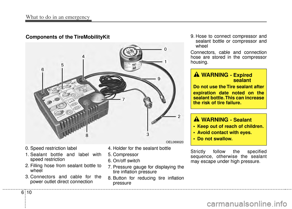
0. Speed restriction label
1. Sealant bottle and label with
speed restriction
2. Filling hose from sealant bottle to wheel
3. Connectors and cable for the power outlet direct connection 4. Holder for the sealant bottle
5. Compressor
6. On/off switch
7. Pressure gauge for displaying the
tire inflation pressure
8. Button for reducing tire inflation pressure 9. Hose to connect compressor and
sealant bottle or compressor and
wheel
Connectors, cable and connection
hose are stored in the compressor
housing.
Strictly follow the specified
sequence, otherwise the sealant
may escape under high pressure.
Components of the TireMobilityKit
OEL069020
WARNING - Expired sealant
Do not use the Tire sealant after
expiration date noted on the
sealant bottle. This can increase
the risk of tire failure.
WARNING - Sealant
• Keep out of reach of children.
Avoid contact with eyes.
Do not swallow.
Page 334 of 446

611
What to do in an emergency
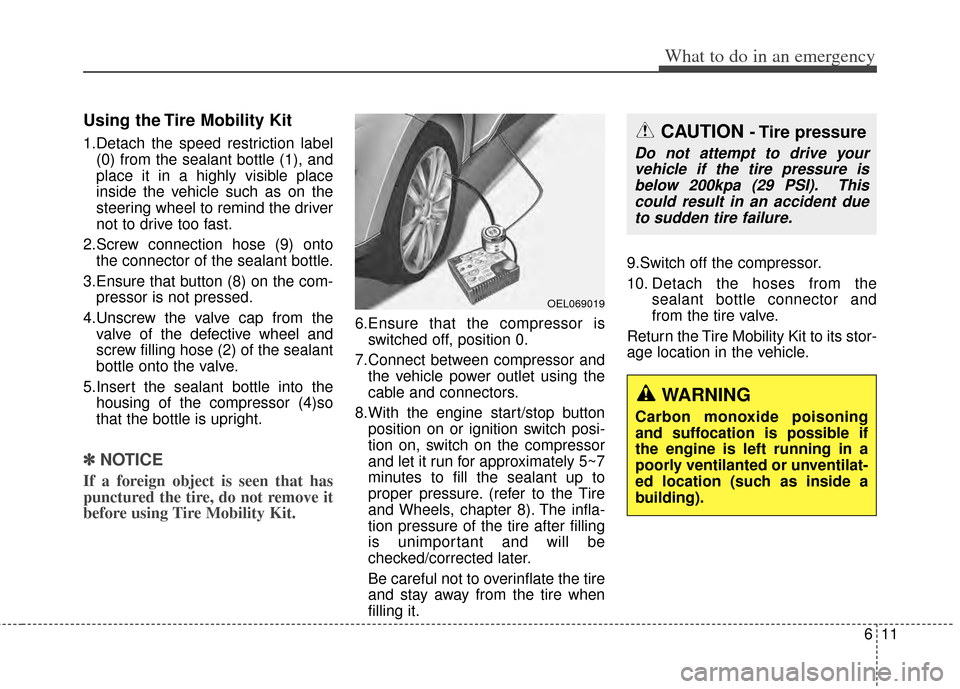
Using the Tire Mobility Kit
1.Detach the speed restriction label(0) from the sealant bottle (1), and
place it in a highly visible place
inside the vehicle such as on the
steering wheel to remind the driver
not to drive too fast.
2.Screw connection hose (9) onto the connector of the sealant bottle.
3.Ensure that button (8) on the com- pressor is not pressed.
4.Unscrew the valve cap from the valve of the defective wheel and
screw filling hose (2) of the sealant
bottle onto the valve.
5.Insert the sealant bottle into the housing of the compressor (4)so
that the bottle is upright.
✽ ✽ NOTICE
If a foreign object is seen that has
punctured the tire, do not remove it
before using Tire Mobility Kit.
6.Ensure that the compressor is
switched off, position 0.
7.Connect between compressor and the vehicle power outlet using the
cable and connectors.
8.With the engine start/stop button position on or ignition switch posi-
tion on, switch on the compressor
and let it run for approximately 5~7
minutes to fill the sealant up to
proper pressure. (refer to the Tire
and Wheels, chapter 8). The infla-
tion pressure of the tire after filling
is unimportant and will be
checked/corrected later.
Be careful not to overinflate the tire
and stay away from the tire when
filling it. 9.Switch off the compressor.
10. Detach the hoses from the
sealant bottle connector and
from the tire valve.
Return the Tire Mobility Kit to its stor-
age location in the vehicle.
OEL069019
CAUTION - Tire pressure
Do not attempt to drive your vehicle if the tire pressure isbelow 200kpa (29 PSI). Thiscould result in an accident dueto sudden tire failure.
WARNING
Carbon monoxide poisoning
and suffocation is possible if
the engine is left running in a
poorly ventilanted or unventilat-
ed location (such as inside a
building).
Page 335 of 446

What to do in an emergency
12
6
Distributing the sealant
11. Immediately drive approximately
7~10km (4~6miles or, about
10min) to evenly distribute the
sealant in the tire.
Do not exceed a speed of 80 km/h
(50 mph). If possible, do not fall
below a speed of 20 km/h (12 mph).
While driving, if you experience any
unusual vibration, ride disturbance or
noise, reduce your speed and drive
with caution until you can safely pull
off of the side of the road.
Call for road side service or towing.
When you use the Tire Mobility Kit,
the tire pressure sensor valve stem
and wheel may be stained by
sealant. After use wipe off sealant
residue and inspect. Consult you Kia
dealership if necessary.
Checking the tire inflation
pressure
1.After driving approximately 7 ~ 10 km (4 ~ 6 miles or about 10 min),
stop at a safe location.
2.Connect connection hose (9) of the compressor directly to the tire
valve.
3.Plug the compressor power cord into the vehicle power outlet.
4.Adjust the tire inflation pressure to the recomended tire inflation.
With the ignition switch on, pro-
ceed as follows.
- To increase the inflation pres-sure : Switch on the compressor,
position I. To check the current
inflation pressure setting, briefly
switch off the compressor.
✽ ✽ NOTICE
The pressure gauge may show high-
er than actual reading when the
compressor is running. To get an
accurate tire reading, the compres-
sor needs to be turned off.
- To reduce the inflation pres-
sure: Press the button 8 on the
compressor.
Page 441 of 446

I3
Index
Climate control air filter . . . . . . . . . . . . . . . . . . . . . . . . 7-37Filter inspection . . . . . . . . . . . . . . . . . . . . . . . . . . . . 7-37
Cruise control system . . . . . . . . . . . . . . . . . . . . . . . . . . 5-35
Defroster . . . . . . . . . . . . . . . . . . . . . . . . . . . . . . . . . . . 4-\
106 Front wiper deicer . . . . . . . . . . . . . . . . . . . . . . . . . 4-106
Rear window defroster . . . . . . . . . . . . . . . . . . . . . . 4-106
Dimensions . . . . . . . . . . . . . . . . . . . . . . . . . . . . . . . . . . . 8-\
2
Door locks. . . . . . . . . . . . . . . . . . . . . . . . . . . . . . . . . . . 4-\
18 Auto door lock/unlock feature . . . . . . . . . . . . . . . . . 4-20
Child-protector rear door lock . . . . . . . . . . . . . . . . . 4-21
From inside. . . . . . . . . . . . . . . . . . . . . . . . . . . . . . . . 4-18
From outside. . . . . . . . . . . . . . . . . . . . . . . . . . . . . . . 4-18
Impact sensing door unlock system . . . . . . . . . . . . . 4-20
Speed sensing door lock system . . . . . . . . . . . . . . . 4-21
Economical operation . . . . . . . . . . . . . . . . . . . . . . . . . . 5-41
Emergency starting . . . . . . . . . . . . . . . . . . . . . . . . . . . . . 6-5 If the engine overheats . . . . . . . . . . . . . . . . . . . . . . . . 6-7
Jump starting . . . . . . . . . . . . . . . . . . . . . . . . . . . . . . . 6-5
Push-starting . . . . . . . . . . . . . . . . . . . . . . . . . . . . . . . . 6-6
Emission control system . . . . . . . . . . . . . . . . . . . . . . . . 7-78 Crankcase emission control system . . . . . . . . . . . . . 7-78 Evaporative emission control
(including ORVR: Onboard Refueling Vapor
Recovery) system . . . . . . . . . . . . . . . . . . . . . . . . . 7-78
Exhaust emission control system . . . . . . . . . . . . . . . 7-79
Engine . . . . . . . . . . . . . . . . . . . . . . . . . . . . . . . . . . . . \
. . . 8-2
Engine compartment . . . . . . . . . . . . . . . . . . . . . . . . 2-6, 7-3
Engine coolant . . . . . . . . . . . . . . . . . . . . . . . . . . . . . . . 7-31 Changing the coolant . . . . . . . . . . . . . . . . . . . . . . . . 7-33
Checking the coolant level . . . . . . . . . . . . . . . . . . . . 7-31
Engine number . . . . . . . . . . . . . . . . . . . . . . . . . . . . . . . 8-10
Engine oil . . . . . . . . . . . . . . . . . . . . . . . . . . . . . . . . . . . 7-\
29 Changing the engine oil and filter . . . . . . . . . . . . . . 7-30
Checking the engine oil level . . . . . . . . . . . . . . . . . 7-29
Engine start/stop button . . . . . . . . . . . . . . . . . . . . . . . . . 5-7 ENGINE START/STOP button position . . . . . . . . . . 5-7
Illuminated ENGINE START/STOP button . . . . . . . 5-7
Explanation of scheduled maintenance items . . . . . . . 7-25
Exterior overview . . . . . . . . . . . . . . . . . . . . . . . . . . . . . . 2-2
Fuel filler lid . . . . . . . . . . . . . . . . . . . . . . . . . . . . . . . . . 4-31 Closing the fuel filler lid . . . . . . . . . . . . . . . . . . . . . 4-31
Opening the fuel filler lid. . . . . . . . . . . . . . . . . . . . . 4-31
Fuel requirements . . . . . . . . . . . . . . . . . . . . . . . . . . . . . . 1-3 Do not use methanol . . . . . . . . . . . . . . . . . . . . . . . . . 1-4
Fuel Additives . . . . . . . . . . . . . . . . . . . . . . . . . . . . . . 1-4
Gasoline containing alcohol and methanol . . . . . . . . 1-3
D
E
F