tow KIA Cerato 2015 2.G User Guide
[x] Cancel search | Manufacturer: KIA, Model Year: 2015, Model line: Cerato, Model: KIA Cerato 2015 2.GPages: 452, PDF Size: 7.85 MB
Page 129 of 452
Features of your vehicle
58
4
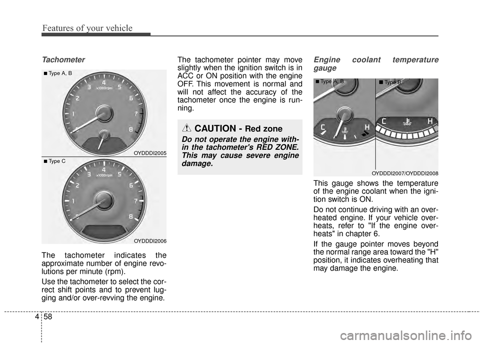
Tachometer
The tachometer indicates the
approximate number of engine revo-
lutions per minute (rpm).
Use the tachometer to select the cor-
rect shift points and to prevent lug-
ging and/or over-revving the engine. The tachometer pointer may move
slightly when the ignition switch is in
ACC or ON position with the engine
OFF. This movement is normal and
will not affect the accuracy of the
tachometer once the engine is run-
ning.
Engine coolant temperature
gauge
This gauge shows the temperature
of the engine coolant when the igni-
tion switch is ON.
Do not continue driving with an over-
heated engine. If your vehicle over-
heats, refer to "If the engine over-
heats" in chapter 6.
If the gauge pointer moves beyond
the normal range area toward the "H"
position, it indicates overheating that
may damage the engine.
OYDDDI2005
OYDDDI2006
■Type A, B
■ Type C
CAUTION - Red zone
Do not operate the engine with-in the tachometer's RED ZONE.This may cause severe enginedamage.
OYDDDI2007/OYDDDI2008
■Type A, B ■Type B
Page 150 of 452
479
Features of your vehicle
Parking Brake & BrakeFluid Warning Light
This warning light illuminates:
Once you set the ignition switch or Engine Start/Stop Button to the ON
position.
- It illuminates for approximately 3seconds
- It remains on if the parking brake is applied.
When the parking brake is applied.
When the brake fluid level in the reservoir is low.
- If the warning light illuminateswith the parking brake released, it
indicates the brake fluid level in
reservoir is low. If the brake fluid level in the reservoir
is low:
1.Drive carefully to the nearest safe
location and stop your vehicle.
2.With the engine stopped, check the brake fluid level immediately and
add fluid as required (For more
details, refer to "Brake Fluid" in
chapter 7).
Then check all brake components
for fluid leaks. If any leak on the
brake system is still found, the
warning light remains on, or the
brakes do not operate properly, do
not drive the vehicle.
In this case, have your vehicle
towed to an authorized Kia dealer
and inspected. Dual-diagonal braking system
Your vehicle is equipped with dual-
diagonal braking systems. This
means you still have braking on two
wheels even if one of the dual sys-
tems should fail.
With only one of the dual systems
working, more than normal pedal
travel and greater pedal pressure are
required to stop the vehicle.
Also, the vehicle will not stop in as
short a distance with only a portion
of the brake system working.
If the brakes fail while you are driv-
ing, shift to a lower gear for addition-
al engine braking and stop the vehi-
cle as soon as it is safe to do so.
Page 170 of 452
499
Features of your vehicle
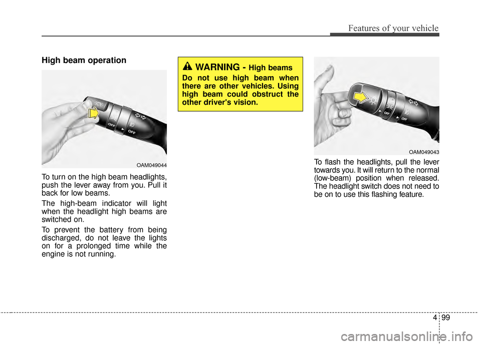
High beam operation
To turn on the high beam headlights,
push the lever away from you. Pull it
back for low beams.
The high-beam indicator will light
when the headlight high beams are
switched on.
To prevent the battery from being
discharged, do not leave the lights
on for a prolonged time while the
engine is not running.To flash the headlights, pull the lever
towards you. It will return to the normal
(low-beam) position when released.
The headlight switch does not need to
be on to use this flashing feature.
OAM049044
WARNING - High beams
Do not use high beam when
there are other vehicles. Using
high beam could obstruct the
other driver's vision.
OAM049043
Page 173 of 452
Features of your vehicle
102
4
Windshield wipers
Operates as follows when the igni-
tion switch is turned ON.
MIST : For a single wiping cycle,
push the lever upward and
release it. The wipers will
operate continuously if the
lever is held in this position.
OFF : Wiper is not in operation
INT : Wiper operates intermittently at the same wiping intervals. Use
this mode in a light rain or mist.
To vary the speed setting, turn
the speed control knob.
LO : Normal wiper speed
HI : Fast wiper speed
If there is a heavy accumulation of
snow or ice on the windshield, defrost
the windshield for about 10 minutes,
or until the snow and/or ice is
removed before using the windshield
wipers to ensure proper operation.
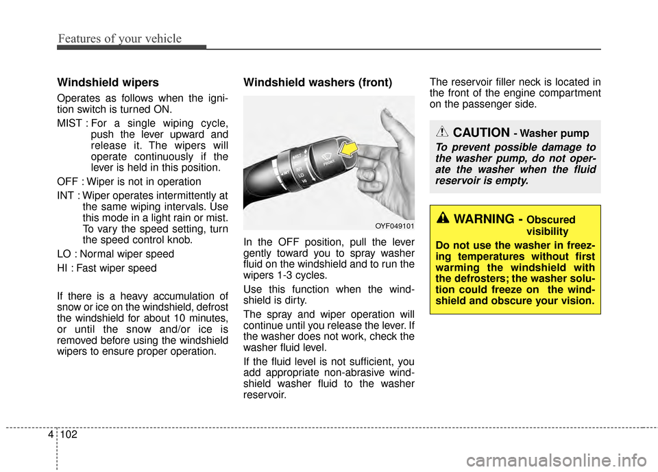
Windshield washers (front)
In the OFF position, pull the lever
gently toward you to spray washer
fluid on the windshield and to run the
wipers 1-3 cycles.
Use this function when the wind-
shield is dirty.
The spray and wiper operation will
continue until you release the lever. If
the washer does not work, check the
washer fluid level.
If the fluid level is not sufficient, you
add appropriate non-abrasive wind-
shield washer fluid to the washer
reservoir. The reservoir filler neck is located in
the front of the engine compartment
on the passenger side.
OYF049101
CAUTION - Washer pump
To prevent possible damage to
the washer pump, do not oper-ate the washer when the fluidreservoir is empty.
WARNING - Obscured
visibility
Do not use the washer in freez-
ing temperatures without first
warming the windshield with
the defrosters; the washer solu-
tion could freeze on the wind-
shield and obscure your vision.
Page 183 of 452
Features of your vehicle
112
4
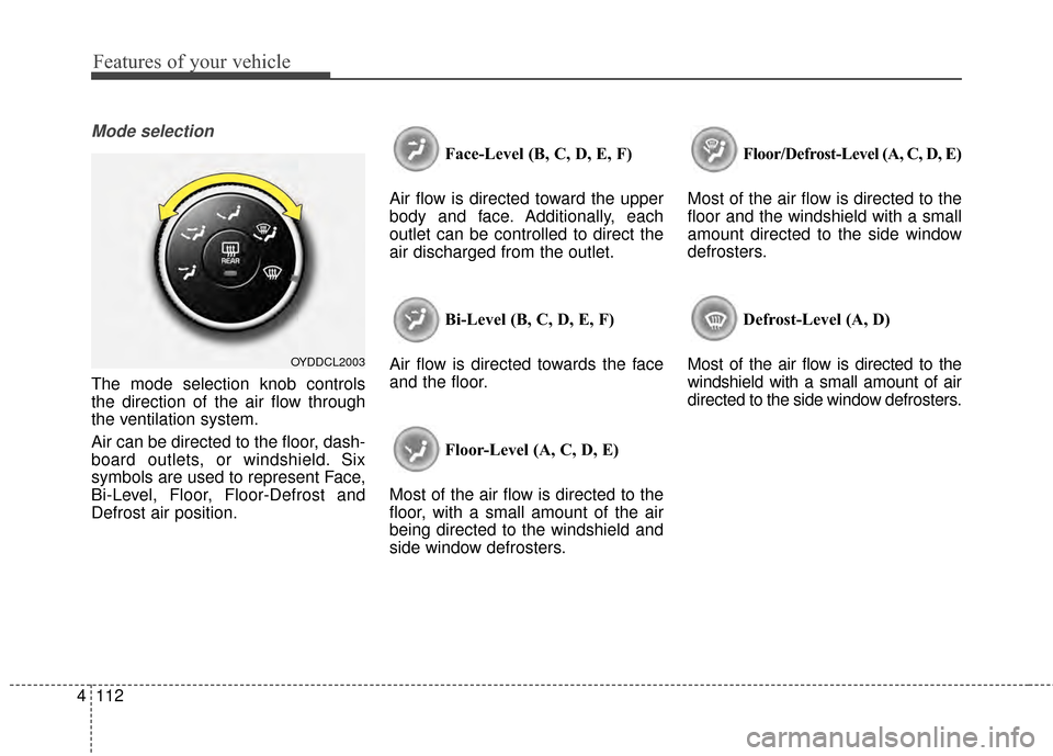
Mode selection
The mode selection knob controls
the direction of the air flow through
the ventilation system.
Air can be directed to the floor, dash-
board outlets, or windshield. Six
symbols are used to represent Face,
Bi-Level, Floor, Floor-Defrost and
Defrost air position. Face-Level (B, C, D, E, F)
Air flow is directed toward the upper
body and face. Additionally, each
outlet can be controlled to direct the
air discharged from the outlet.
Bi-Level (B, C, D, E, F)
Air flow is directed towards the face
and the floor.
Floor-Level (A, C, D, E)
Most of the air flow is directed to the
floor, with a small amount of the air
being directed to the windshield and
side window defrosters. Floor/Defrost-Level (A, C, D, E)
Most of the air flow is directed to the
floor and the windshield with a small
amount directed to the side window
defrosters.
Defrost-Level (A, D)
Most of the air flow is directed to the
windshield with a small amount of air
directed to the side window defrosters.
OYDDCL2003
Page 184 of 452
4113
Features of your vehicle
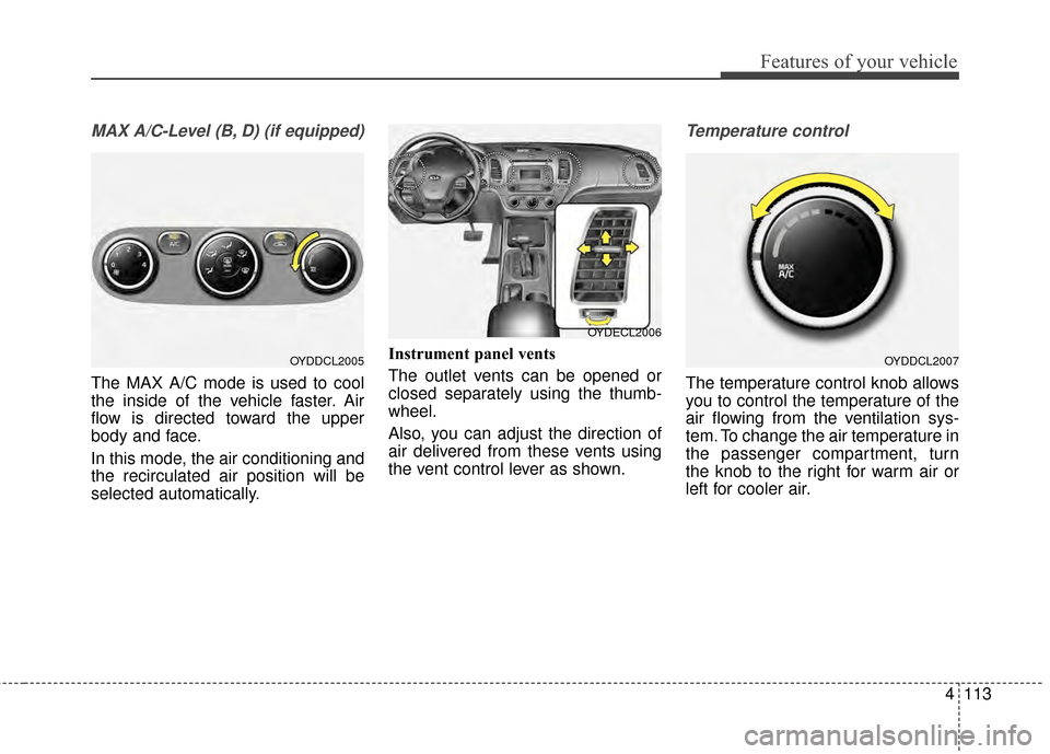
MAX A/C-Level (B, D) (if equipped)
The MAX A/C mode is used to cool
the inside of the vehicle faster. Air
flow is directed toward the upper
body and face.
In this mode, the air conditioning and
the recirculated air position will be
selected automatically.Instrument panel vents
The outlet vents can be opened or
closed separately using the thumb-
wheel.
Also, you can adjust the direction of
air delivered from these vents using
the vent control lever as shown.
Temperature control
The temperature control knob allows
you to control the temperature of the
air flowing from the ventilation sys-
tem. To change the air temperature in
the passenger compartment, turn
the knob to the right for warm air or
left for cooler air.
OYDDCL2005OYDDCL2007
OYDECL2006
Page 194 of 452
4123
Features of your vehicle
Face-Level (B, C, D, E, F)
Air flow is directed toward the upper
body and face. Additionally, each
outlet can be controlled to direct the
air discharged from the outlet.
Bi-Level (B, C, D, E, F)
Air flow is discharged towards the
face and floor. Floor-Level (C, A, D, E)
Most of the air flow is directed to the
floor, with a small amount of the air
being directed to the windshield and
side window defroster.
Floor/Defrost-Level (A, C, D, E)
Most of the air flow is directed to the
floor and the windshield with a small
amount directed to the side window
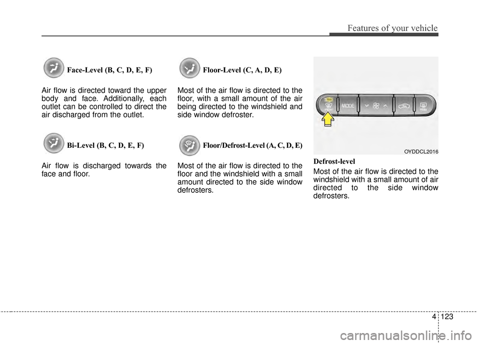
defrosters. Defrost-level
Most of the air flow is directed to the
windshield with a small amount of air
directed to the side window
defrosters.
OYDDCL2016
Page 204 of 452
4133
Features of your vehicle
If the battery has been discharged or
disconnected, it resets to the defog
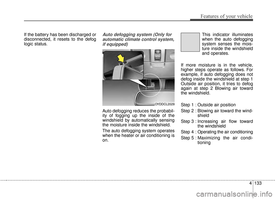
logic status.Auto defogging system (Only forautomatic climate control system,if equipped)
Auto defogging reduces the probabil-
ity of fogging up the inside of the
windshield by automatically sensing
the moisture inside the windshield.
The auto defogging system operates
when the heater or air conditioning is
on. This indicator illuminates
when the auto defogging
system senses the mois-
ture inside the windshield
and operates.
If more moisture is in the vehicle,
higher steps operate as follows. For
example, if auto defogging does not
defog inside the windshield at step 1
Outside air position, it tries to defog
again at step 2 Blowing air toward
the windshield.
Step 1 : Outside air position
Step 2 : Blowing air toward the wind- shield
Step 3 : Increasing air flow toward the windshield
Step 4 : Operating the air conditioning
Step 5 : Maxim izing the air condi-
tioning
OYDDCL2029
Page 221 of 452
Features of your vehicle
150
4
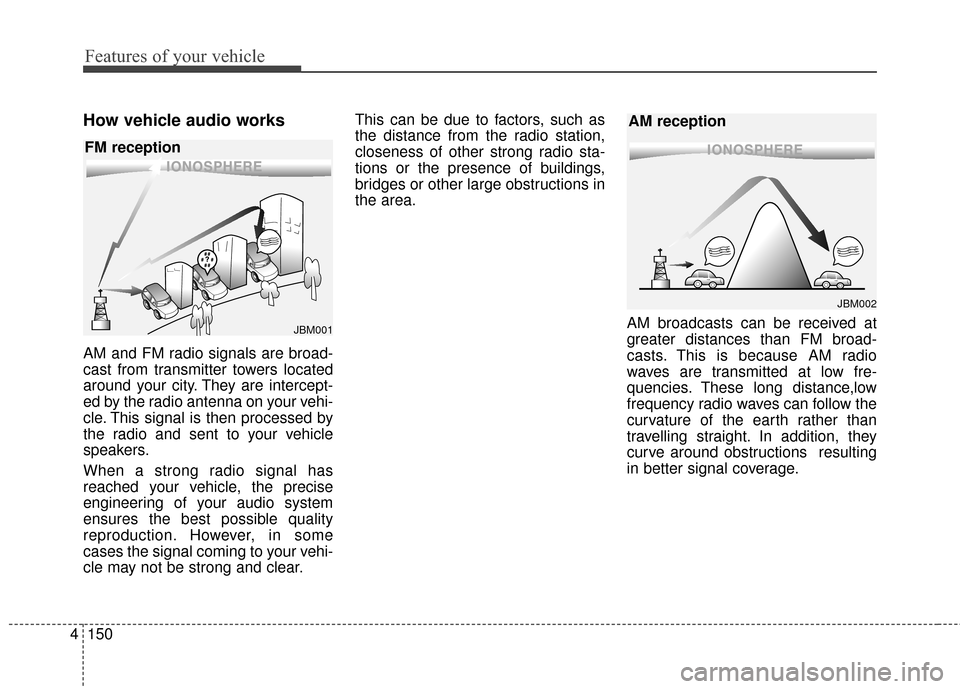
How vehicle audio works
AM and FM radio signals are broad-
cast from transmitter towers located
around your city. They are intercept-
ed by the radio antenna on your vehi-
cle. This signal is then processed by
the radio and sent to your vehicle
speakers.
When a strong radio signal has
reached your vehicle, the precise
engineering of your audio system
ensures the best possible quality
reproduction. However, in some
cases the signal coming to your vehi-
cle may not be strong and clear. This can be due to factors, such as
the distance from the radio station,
closeness of other strong radio sta-
tions or the presence of buildings,
bridges or other large obstructions in
the area.
AM broadcasts can be received at
greater distances than FM broad-
casts. This is because AM radio
waves are transmitted at low fre-
quencies. These long distance,low
frequency radio waves can follow the
curvature of the earth rather than
travelling straight. In addition, they
curve around obstructions resulting
in better signal coverage.
¢¢¢¢¢¢
JBM002
AM reception
¢¢¢
JBM001
FM reception
Page 274 of 452
Driving your vehicle
Before driving . . . . . . . . . . . . . . . . . . . . . . . . . . . . . . 5-3
Key positions . . . . . . . . . . . . . . . . . . . . . . . . . . . . . . . 5-5
Engine start/stop button . . . . . . . . . . . . . . . . . . . . . 5-7
• Illuminated ENGINE START/STOP button . . . . . . . 5-7
. . . . . . . . . . . 5-7
Starting the engine . . . . . . . . . . . . . . . . . . . . . . . . . 5-10
Manual transaxle . . . . . . . . . . . . . . . . . . . . . . . . . . 5-13
. . . . . . . . . . . . . . . . . . . . 5-13
Automatic transaxle . . . . . . . . . . . . . . . . . . . . . . . . 5-16
. . . . . . . . . . . . . . . . . . 5-16
Brake system . . . . . . . . . . . . . . . . . . . . . . . . . . . . . . 5-22
. . . . . . . . . . . . . . . . . . . . . . . . . . . . . . . . 5-22
. . . . . . . . . . . . . . . . . . . . . . . . . . . . . . . 5-23
. . . . . . . . . . . . . . . . . . 5-25
. . . . . . . . . . . . . . . 5-27
. . . . . . . . . . . . . . . . . . 5-31
. . . . . . . . . . . . 5-31
Cruise control system. . . . . . . . . . . . . . . . . . . . . . . 5-35
Active eco system . . . . . . . . . . . . . . . . . . . . . . . . . . 5-40
Economical operation . . . . . . . . . . . . . . . . . . . . . . 5-41Special driving conditions . . . . . . . . . . . . . . . . . . . 5-43
. . . . . . . . . . . . . . . . . . 5-43
. . . . . . . . . . . . . . . . . . . . . . . . . . . 5-43
. . . . . . . . . . . . . . . . . . . . . . . . . . . . 5-44
. . . . . . . . . . . . . . . . . . . . . . . . . . . . . . 5-44
. . . . . . . . . . . . . . . . . . . . . . . . . . . . 5-45
. . . . . . . . . . . . . . . . . . . . . . . 5-45
. . . . . . . . . . . . . . . . . . . . . . . . . . . . . . 5-46
. . . . . . . . . . . . . . . . . . . . . . . . . . . . . 5-46
Winter driving . . . . . . . . . . . . . . . . . . . . . . . . . . . . 5-47
Trailer towing . . . . . . . . . . . . . . . . . . . . . . . . . . . . . 5-49
Vehicle load limit . . . . . . . . . . . . . . . . . . . . . . . . . . 5-50
. . . . . . . . . . . . . . 5-50
. . . . . . . . . . . . . . . . . . . . . . . . . . . . 5-53
Vehicle weight . . . . . . . . . . . . . . . . . . . . . . . . . . . . . 5-55
. . . . . . . . . . . . . . . . . . . . . . . . . . . . . 5-55
. . . . . . . . . . . . . . . . . . . . . . . . . . . 5-55
. . . . . . . . . . . . . . . . . . . . . . . . . . . . . . . . 5-55
. . . . . . . . . . . . . . . . . . . . . . 5-55
. . . . . . . . . . . . . . . 5-55
. . . . . . . . . . . . . . . . . . . 5-55
. . . . . . . . . . . . 5-55
5