clock KIA K900 2019 Owners Manual
[x] Cancel search | Manufacturer: KIA, Model Year: 2019, Model line: K900, Model: KIA K900 2019Pages: 580, PDF Size: 15.11 MB
Page 16 of 580
25
Your vehicle at a glance
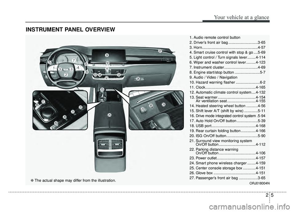
INSTRUMENT PANEL OVERVIEW
1. Audio remote control button
2. Driver’s front air bag ............................3-65
3. Horn.....................................................4-57
4. Smart cruise control with stop & go ....5-69
5. Light control / Turn signals lever ........4-114
6. Wiper and washer control lever .........4-123
7. Instrument cluster ................................4-69
8. Engine start/stop button ........................5-7
9. Audio / Video / Navigation
10. Hazard warning flasher .......................6-2
11. Clock................................................4-165
12. Automatic climate control system ....4-132
13. Seat warmer ....................................4-154Air ventilation seat ...........................4-155
14. Heated steering wheel button ...........4-56
15. Shift lever A/T (shift by wire) .............5-11
16. Drive mode integrated control system .5-94
17. Auto Hold On/Off button ....................5-39
18. USB port..........................................4-168
19. Rear curtain folding button ..............4-166
20. ISG On/Off button..............................5-90
21. Surround view monitoring system On/Off button ...................................4-112
22. Parking distance warning On/Off button ...................................4-106
23. Power outlet.....................................4-157
24. Smart phone wireless charger ........4-159
25. Center console storage box ............4-151
26. Glove box ........................................4-151
27. Passenger’s front air bag ..................3-65
ORJ018004N❈ The actual shape may differ from the illustration.
Page 29 of 580
Safety features of your vehicle
12
3
Seat back bolster control
(For driver seat, if equipped)
1. Turn the adjustment switch clock- wise, the right/left seatback bol-
sters will be adjusted inward. Turn
the switch counterclockwise, the
seatback bolster will be adjusted
outward. 2. To adjust the bolster height to its
maximum in the default state,
operate the switch for 8 seconds.
After that, release the switch
because there is no change in
height even if you continue to
operate the switch.
3. Once adjustment is done, leave the switch in place.
Walk-in Seat (for front passenger
seat, if equipped)
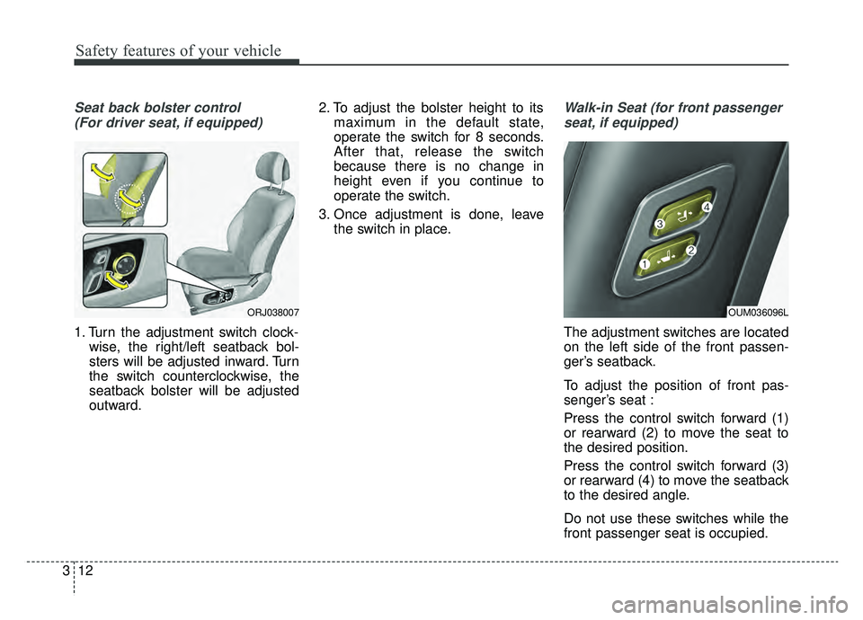
The adjustment switches are located
on the left side of the front passen-
ger’s seatback.
To adjust the position of front pas-
senger’s seat :
Press the control switch forward (1)
or rearward (2) to move the seat to
the desired position.
Press the control switch forward (3)
or rearward (4) to move the seatback
to the desired angle.
Do not use these switches while the
front passenger seat is occupied.
ORJ038007OUM036096L
Page 96 of 580
Welcome system . . . . . . . . . . . . . . . . . . . . . . . . . . 4-130
• Headlight (Headlamp) escort function . . . . . . . . . . 4-130
• Interior light. . . . . . . . . . . . . . . . . . . . . . . . . . . . . . . . 4-130
• Pocket lamp . . . . . . . . . . . . . . . . . . . . . . . . . . . . . . . . 4-130
Defroster . . . . . . . . . . . . . . . . . . . . . . . . . . . . . . . . 4-131
• Rear window defroster . . . . . . . . . . . . . . . . . . . . . . . 4-131
Automatic climate control system . . . . . . . . . . . 4-132
• Automatic heating and air conditioning . . . . . . . . . 4-133
• Manual heating and air conditioning . . . . . . . . . . . 4-135
• System operation . . . . . . . . . . . . . . . . . . . . . . . . . . . . 4-142
• Climate control air filter . . . . . . . . . . . . . . . . . . . . . . 4-144
• Checking the amount of air conditionerrefrigerant and compressor lubricant . . . . . . . . . . 4-144
• Air Conditioning refrigerant label. . . . . . . . . . . . . . 4-145
Windshield defrosting and defogging . . . . . . . . . 4-146
• Automatic climate control system . . . . . . . . . . . . . . 4-146
• Defogging logic. . . . . . . . . . . . . . . . . . . . . . . . . . . . . . 4-147
• Automatic ventilation . . . . . . . . . . . . . . . . . . . . . . . . 4-149
• Smart ventilation . . . . . . . . . . . . . . . . . . . . . . . . . . . . 4-150
Storage compartments . . . . . . . . . . . . . . . . . . . . . 4-151
• Center console storage . . . . . . . . . . . . . . . . . . . . . . . 4-151
• Glove box . . . . . . . . . . . . . . . . . . . . . . . . . . . . . . . . . . 4-15\
1
• Sunglass holder . . . . . . . . . . . . . . . . . . . . . . . . . . . . . 4-152
Interior features . . . . . . . . . . . . . . . . . . . . . . . . . . 4-153
• Cup holder . . . . . . . . . . . . . . . . . . . . . . . . . . . . . . . . . 4-153
• Seat warmer . . . . . . . . . . . . . . . . . . . . . . . . . . . . . . . . 4-154
• Air ventilation seat . . . . . . . . . . . . . . . . . . . . . . . . . . 4-155
• Sunvisor . . . . . . . . . . . . . . . . . . . . . . . . . . . . . . . . . . . 4-\
156
• Power outlet . . . . . . . . . . . . . . . . . . . . . . . . . . . . . . . . 4-157
• USB charger . . . . . . . . . . . . . . . . . . . . . . . . . . . . . . . . 4-158
• Wireless smart phone charging system . . . . . . . . . . 4-159
• Coat hook . . . . . . . . . . . . . . . . . . . . . . . . . . . . . . . . . . 4-16\
2
• Floor mat anchor (s) . . . . . . . . . . . . . . . . . . . . . . . . . 4-163
• Luggage net (holder) . . . . . . . . . . . . . . . . . . . . . . . . . 4-164
• Clock . . . . . . . . . . . . . . . . . . . . . . . . . . . . . . . . . . . . \
. . 4-165
• Bag hanger . . . . . . . . . . . . . . . . . . . . . . . . . . . . . . . . . 4-165
• Side curtain . . . . . . . . . . . . . . . . . . . . . . . . . . . . . . . . 4-165
• Rear curtain . . . . . . . . . . . . . . . . . . . . . . . . . . . . . . . . 4-166
Audio system . . . . . . . . . . . . . . . . . . . . . . . . . . . . . 4-167
• USB port . . . . . . . . . . . . . . . . . . . . . . . . . . . . . . . . . . . 4-\
168
• How vehicle radio works . . . . . . . . . . . . . . . . . . . . . 4-168
Declaration of Conformity . . . . . . . . . . . . . . . . . 4-171
• FCC . . . . . . . . . . . . . . . . . . . . . . . . . . . . . . . . . . . . \
. . . 4-171
4
Page 110 of 580
417
Features of your vehicle
DOOR LOCKS
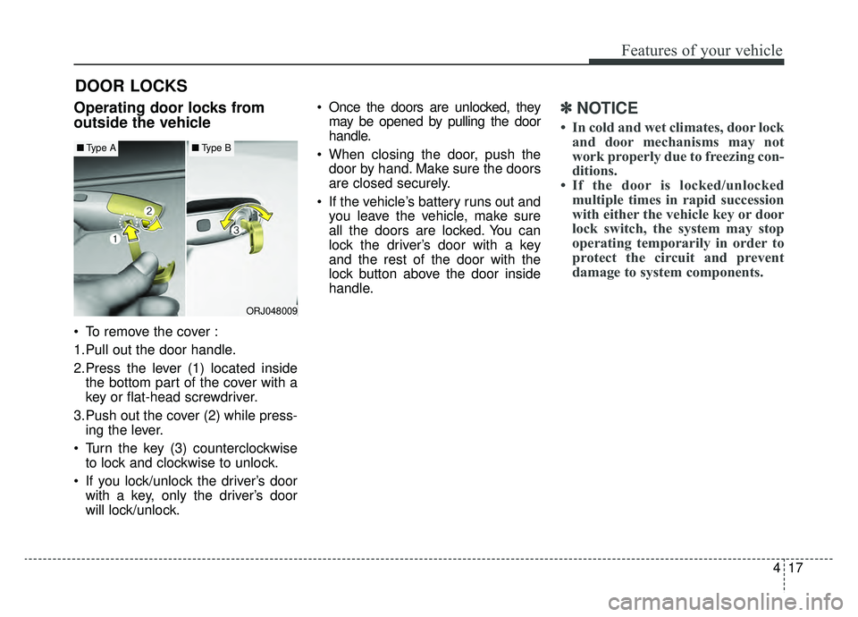
Operating door locks from
outside the vehicle
To remove the cover :
1.Pull out the door handle.
2.Press the lever (1) located insidethe bottom part of the cover with a
key or flat-head screwdriver.
3.Push out the cover (2) while press- ing the lever.
Turn the key (3) counterclockwise to lock and clockwise to unlock.
If you lock/unlock the driver’s door with a key, only the driver’s door
will lock/unlock. Once the doors are unlocked, they
may be opened by pulling the door
handle.
When closing the door, push the door by hand. Make sure the doors
are closed securely.
If the vehicle’s battery runs out and you leave the vehicle, make sure
all the doors are locked. You can
lock the driver’s door with a key
and the rest of the door with the
lock button above the door inside
handle.
✽ ✽ NOTICE
• In cold and wet climates, door lock
and door mechanisms may not
work properly due to freezing con-
ditions.
• If the door is locked/unlocked multiple times in rapid succession
with either the vehicle key or door
lock switch, the system may stop
operating temporarily in order to
protect the circuit and prevent
damage to system components.
ORJ048009
■ Type A■Type B
Page 137 of 580
Features of your vehicle
44
4
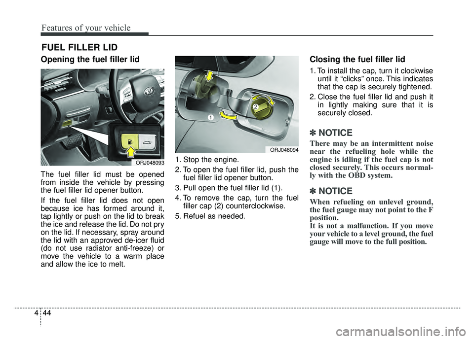
Opening the fuel filler lid
The fuel filler lid must be opened
from inside the vehicle by pressing
the fuel filler lid opener button.
If the fuel filler lid does not open
because ice has formed around it,
tap lightly or push on the lid to break
the ice and release the lid. Do not pry
on the lid. If necessary, spray around
the lid with an approved de-icer fluid
(do not use radiator anti-freeze) or
move the vehicle to a warm place
and allow the ice to melt. 1. Stop the engine.
2. To open the fuel filler lid, push the
fuel filler lid opener button.
3. Pull open the fuel filler lid (1).
4. To remove the cap, turn the fuel filler cap (2) counterclockwise.
5. Refuel as needed.
Closing the fuel filler lid
1. To install the cap, turn it clockwise until it “clicks” once. This indicates
that the cap is securely tightened.
2. Close the fuel filler lid and push it in lightly making sure that it is
securely closed.
✽ ✽NOTICE
There may be an intermittent noise
near the refueling hole while the
engine is idling if the fuel cap is not
closed securely. This occurs normal-
ly with the OBD system.
✽ ✽NOTICE
When refueling on unlevel ground,
the fuel gauge may not point to the F
position.
It is not a malfunction. If you move
your vehicle to a level ground, the fuel
gauge will move to the full position.
FUEL FILLER LID
ORJ048093
ORJ048094
Page 258 of 580
4165
Features of your vehicle
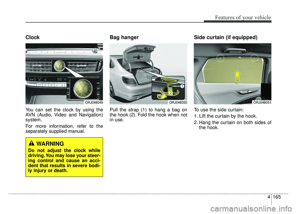
Clock
You can set the clock by using the
AVN (Audio, Video and Navigation)
system.
For more information, refer to the
separately supplied manual.
Bag hanger
Pull the strap (1) to hang a bag on
the hook (2). Fold the hook when not
in use.
Side curtain (if equipped)
To use the side curtain:
1. Lift the curtain by the hook.
2. Hang the curtain on both sides ofthe hook.
ORJ048050ORJ048051ORJ048049
WARNING
Do not adjust the clock while
driving. You may lose your steer-
ing control and cause an acci-
dent that results in severe bodi-
ly injury or death.
Page 369 of 580
Driving your vehicle
104
5
- If the number of lanes increases
or decreases, or if the lanes inter-
sect with each other more
intensely (tollgate entry section,
road section / joining section,
etc.)
- When there are two or more lane markings such as a construction
section, a designated lane, etc.
- When the lane is crowded such as the construction section or the
lane is replaced by some struc-
tures
- If there is a road marking such as a zigzag lane, crosswalk mark, or
road surface milestone
- When a lane suddenly becomes invisible or disappears from an
intersection
• The external environment affecting the system
- If the outside brightness of the vehi- cle suddenly changes, such as
when entering or exiting the tunnel
or passing under the bridge - If the vehicle's headlights are not
used at night or in the tunnel, or the
brightness of the headlights is too
weak
- If there are boundary structures such as tollgate booths and side-
walk blocks
- If it is difficult to distinguish lanes due to the reflection on the wet road
made by sunlight, streetlight, and
oncoming traffic.
- When the backlight is strongly reflect- ed in the direction of the vehicle
- When Driving to the left or right lane by bus lane or on the bus lane
- If there is not enough distance between the front car or if the lane
is covered by the car ahead of me
- When the lane change is large, such as a steep curve or a continu-
ous curve
- When passing through speed bump, sudden up / down or left /
right slope
- If the vehicle is severely shaken
- When the temperature around the rearview mirror is very high due to
direct sunlight • If the front camera clock is of poor
quality
- If the windshield of the vehicle and the front part of the lens of
the product are covered with
dust, fingerprints, or tinting
- If the clock doesn¡¯t work proper- ly due to bad weather such as
fog, heavy rain or heavy snow.
- If moisture is not completely removed from the windscreen.
- When placing an object on the dashboard, etc.
Page 441 of 580
615
What to do in an emergency
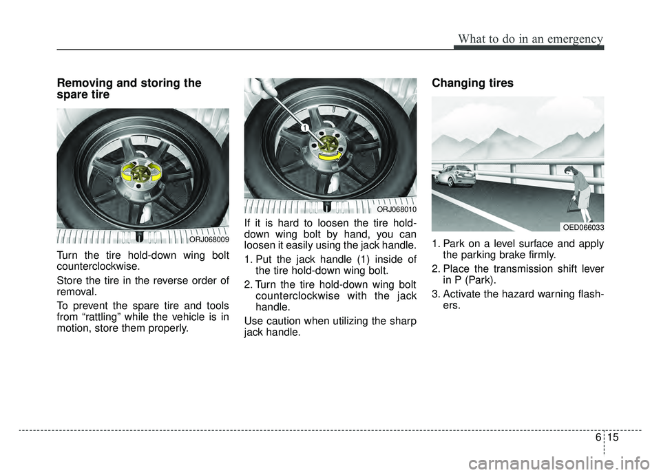
Removing and storing the
spare tire
Turn the tire hold-down wing bolt
counterclockwise.
Store the tire in the reverse order of
removal.
To prevent the spare tire and tools
from “rattling” while the vehicle is in
motion, store them properly.If it is hard to loosen the tire hold-
down wing bolt by hand, you can
loosen it easily using the jack handle.
1. Put the jack handle (1) inside of
the tire hold-down wing bolt.
2. Turn the tire hold-down wing bolt counterclockwise with the jack
handle.
Use caution when utilizing the sharp
jack handle.
Changing tires
1. Park on a level surface and apply the parking brake firmly.
2. Place the transmission shift lever in P (Park).
3. Activate the hazard warning flash- ers.ORJ068009
ORJ068010
OED066033
Page 443 of 580
617
What to do in an emergency
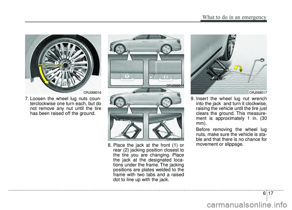
7. Loosen the wheel lug nuts coun-terclockwise one turn each, but do
not remove any nut until the tire
has been raised off the ground.
8. Place the jack at the front (1) orrear (2) jacking position closest to
the tire you are changing. Place
the jack at the designated loca-
tions under the frame. The jacking
positions are plates welded to the
frame with two tabs and a raised
dot to line up with the jack. 9. Insert the wheel lug nut wrench
into the jack and turn it clockwise,
raising the vehicle until the tire just
clears the ground. This measure-
ment is approximately 1 in. (30
mm).
Before removing the wheel lug
nuts, make sure the vehicle is sta-
ble and that there is no chance for
movement or slippage.
ORJ068017ORJ068016
ORJ068014
ORJ068015
Page 444 of 580
What to do in an emergency
18
6
9. Loosen the wheel nuts and
remove them with your fingers.
Slide the wheel off the studs and
lay it flat so it cannot roll away. To
put the wheel on the hub, pick up
the spare tire, line up the holes
with the studs and slide the wheel
onto them. If this is difficult, tip the
wheel slightly and get the top hole
in the wheel lined up with the top
stud. Jiggle the wheel back and
forth until the wheel can slide over
the other studs. Wheels may have sharp edges.
Handle them carefully to avoid possi-
ble severe injury. Before putting the
wheel into place, be sure that there
is nothing on the hub or wheel (such
as mud, tar, gravel, etc.) that pre-
vents the wheel from fitting solidly
against the hub.
10. To install the wheel, hold it on the
studs, put the wheel nuts on the
studs and tighten them finger
tight. Jiggle the tire to be sure it is
completely seated, then tighten
the nuts as much as possible
with your fingers again.
11. Insert the wrench into the jack and lower the vehicle to the
ground by turning the wheel nut
wrench counterclockwise.
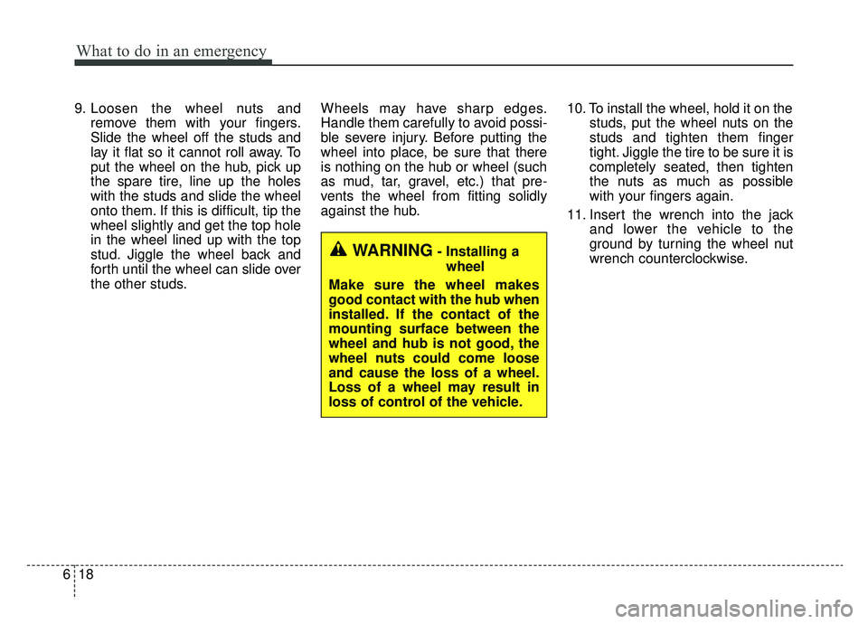
WARNING- Installing a
wheel
Make sure the wheel makes
good contact with the hub when
installed. If the contact of the
mounting surface between the
wheel and hub is not good, the
wheel nuts could come loose
and cause the loss of a wheel.
Loss of a wheel may result in
loss of control of the vehicle.