power outlet KIA NIRO 2021 Owners Manual
[x] Cancel search | Manufacturer: KIA, Model Year: 2021, Model line: NIRO, Model: KIA NIRO 2021Pages: 710, PDF Size: 14.77 MB
Page 9 of 710
H4
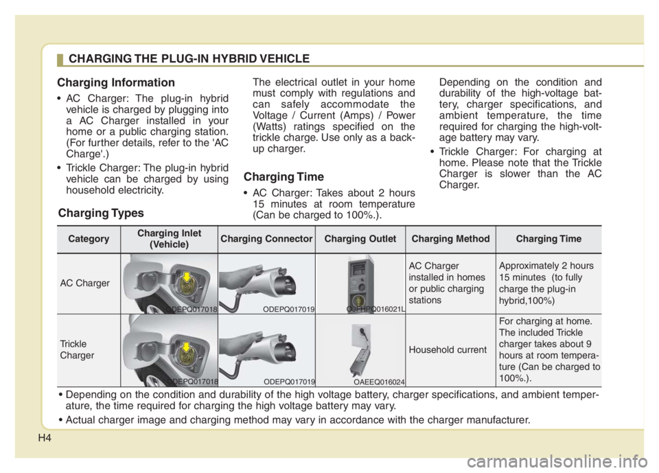
Charging Information
• AC Charger: The plug-in hybrid
vehicle is charged by plugging into
a AC Charger installed in your
home or a public charging station.
(For further details, refer to the 'AC
Charge'.)
Trickle Charger: The plug-in hybrid
vehicle can be charged by using
household electricity.The electrical outlet in your home
must comply with regulations and
can safely accommodate the
Voltage / Current (Amps) / Power
(Watts) ratings specified on the
trickle charge. Use only as a back-
up charger.
Charging Time
AC Charger: Takes about 2 hours
15 minutes at room temperature
(Can be charged to 100%.).Depending on the condition and
durability of the high-voltage bat-
tery, charger specifications, and
ambient temperature, the time
required for charging the high-volt-
age battery may vary.
Trickle Charger: For charging at
home. Please note that the Trickle
Charger is slower than the AC
Charger.
CHARGING THE PLUG-IN HYBRID VEHICLE
Charging Types
ature, the time required for charging the high voltage battery may vary.
CategoryCharging Inlet
(Vehicle)Charging ConnectorCharging OutletCharging Method Charging Time
AC Charger
AC Charger
installed in homes
or public charging
stations Approximately 2 hours
15 minutes (to fully
charge the plug-in
hybrid,100%)
Trickle
ChargerHousehold current
For charging at home.
The included Trickle
charger takes about 9
hours at room tempera-
ture (Can be charged to
100%.).
ODEPQ017018
ODEPQ017019
ODEPQ017019
OAEEQ016024 OJFHPQ016021L
ODEPQ017018
Page 23 of 710
H18
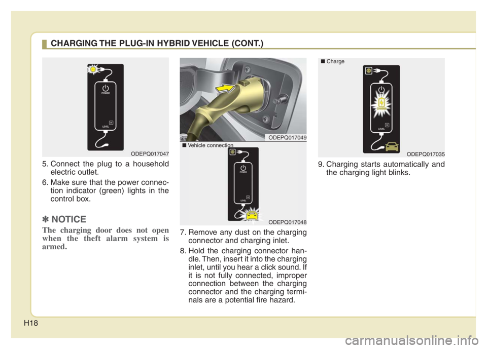
5. Connect the plug to a household
electric outlet.
6. Make sure that the power connec-
tion indicator (green) lights in the
control box.
✽ ✽
NOTICE
The charging door does not open
when the theft alarm system is
armed.7. Remove any dust on the charging
connector and charging inlet.
8. Hold the charging connector han-
dle. Then, insert it into the charging
inlet, until you hear a click sound. If
it is not fully connected, improper
connection between the charging
connector and the charging termi-
nals are a potential fire hazard.9. Charging starts automatically and
the charging light blinks.
ODEPQ017047
CHARGING THE PLUG-IN HYBRID VEHICLE (CONT.)
ODEPQ017049
ODEPQ017048
■Vehicle connection
ODEPQ017035 ■Charge
Page 66 of 710
25
Your vehicle at a glance
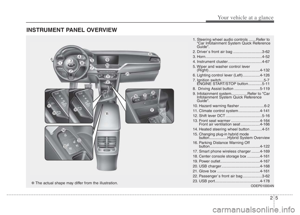
INSTRUMENT PANEL OVERVIEW
1. Steering wheel audio controls .......Refer to
"Car Infotainment System Quick Reference
Guide".
2. Driver`s front air bag ...........................3-62
3. Horn.....................................................4-52
4. Instrument cluster ................................4-67
5. Wiper and washer control lever
(Right) ................................................4-132
6. Lighting control lever (Left) ................4-126
7. Ignition switch........................................5-7
ENGINE START/STOP button .............5-11
8. Driving Assist button ........................5-119
9. Infotainment system...............Refer to "Car
Infotainment System Quick Reference
Guide".
10. Hazard warning flasher .......................6-2
11. Climate control system ....................4-141
12. Shift lever DCT ..................................5-16
13. Front seat warmer ...........................4-164
Front air ventilation seat ..................4-166
14. Heated steering wheel button ...........4-51
15. Changing plug-in hybrid mode
button..................Hybrid System Overview
16. Parking Distance Warning Off
button...............................................4-122
17. Smart phone wireless charger ........4-169
18. Center console storage box ............4-161
19. Power outlet.....................................4-167
20. USB charger ....................................4-168
21. Glove box ........................................4-161
22. Passenger`s front air bag ..................3-62
23. USB port..........................................4-178
ODEP010004N❈The actual shape may differ from the illustration.
Page 307 of 710
4167
Features of your vehicle
Sun visor
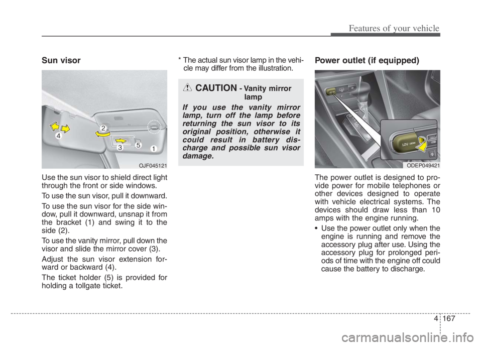
Use the sun visor to shield direct light
through the front or side windows.
To use the sun visor, pull it downward.
To use the sun visor for the side win-
dow, pull it downward, unsnap it from
the bracket (1) and swing it to the
side (2).
To use the vanity mirror, pull down the
visor and slide the mirror cover (3).
Adjust the sun visor extension for-
ward or backward (4).
The ticket holder (5) is provided for
holding a tollgate ticket.* The actual sun visor lamp in the vehi-
cle may differ from the illustration.
Power outlet (if equipped)
The power outlet is designed to pro-
vide power for mobile telephones or
other devices designed to operate
with vehicle electrical systems. The
devices should draw less than 10
amps with the engine running.
Use the power outlet only when the engine is running and remove the
accessory plug after use. Using the
accessory plug for prolonged peri-
ods of time with the engine off could
cause the battery to discharge.
CAUTION- Vanity mirror
lamp
If you use the vanity mirrorlamp, turn off the lamp beforereturning the sun visor to itsoriginal position, otherwise itcould result in battery dis-charge and possible sun visordamage.
ODEP049421 OJF045121
Page 308 of 710

Features of your vehicle
168 4
Only use 12V electric accessories
which are less than 10A in electric
capacity.
Adjust the air-conditioner or heater
to the lowest operating level when
using the power outlet.
Close the cover when not in use.
Some electronic devices can cause
electronic interference when
plugged into a vehicle’s power out-
let. These devices may cause
excessive audio static and malfunc-
tions in other electronic systems or
devices used in your vehicle.
Push the plug in as far as it will go.
If good contact is not made, the
plug may overheat and the fuse
may open.
Plug in battery equipped electronic
devices with reverse current pro-
tection. The current from the bat-
tery may flow into the vehicle’s
electri cal/electronic system and
cause system malfunction.USB charger (if equipped)
The USB charger is designed to
recharge batteries of small size elec-
trical devices using a USB cable. The
electrical devices can be recharged
when the Engine Start/Stop button is
in ACC/ON/START position.
The battery charging state may be
monitored on the electrical device.
Disconnect the USB cable from the
USB port after use.
Some devices are not supported
for fast charging but will be
charged with normal speed.
WARNING - Electric shock
Do not put a finger or a foreign
object (pen, etc.) into a power
outlet and do not touch with a
wet hand. You may receive an
electric shock.
ODEP049532
Page 552 of 710
What to do in an emergency
32 6
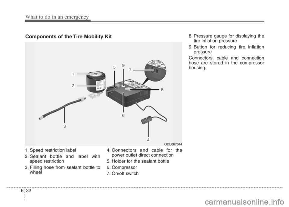
1. Speed restriction label
2. Sealant bottle and label with
speed restriction
3. Filling hose from sealant bottle to
wheel4. Connectors and cable for the
power outlet direct connection
5. Holder for the sealant bottle
6. Compressor
7. On/off switch8. Pressure gauge for displaying the
tire inflation pressure
9. Button for reducing tire inflation
pressure
Connectors, cable and connection
hose are stored in the compressor
housing.
Components of the Tire Mobility Kit
ODE067044
Page 555 of 710

635
What to do in an emergency
6. Ensure that the compressor is
switched off, position 0.
7. Connect between compressor and
the vehicle power outlet using the
cable and connectors (4).
8. With the engine start/stop button
position on or ignition switch posi-
tion on, switch on the compressor
and let it run for approximately 5 ~
7 minutes to fill the sealant up to
cold tire recommended pressure.
(Refer to “Tires and wheels” in
chapter 8.). Be careful not to over-
inflate the tire and stay away from
the tire when filling it. When the tire
and wheel are damaged, do not
use Tire Mobility Kit for your safety.9. Switch off the compressor.
10. Detach the hoses from the
sealant bottle connector and
from the tire valve.
Return the Tire Mobility Kit to its stor-
age location in the vehicle.
Distributing the sealant
11. Immediately drive approximately
4 ~ 6 miles (7 ~ 10 km or, about
10 min) to evenly distribute the
sealant in the tire.
Do not exceed a speed of 50 mph
(80 km/h). If possible, do not fall
below a speed of 12 mph (20 km/h).
While driving, if you experience any
unusual vibration, ride disturbance or
noise, reduce your speed and drive
with caution until you can safely pull
off of the side of the road.
ODEP069008
WARNING - Carbon
monoxide
Carbon monoxide poisoning
and suffocation is possible if
the engine is left running in a
poorly ventilated or unventilat-
ed location (such as inside a
building).
ODE066040N
WARNING - Tire pressure
Do not attempt to drive your
vehicle if the tire pressure is
below 29 psi (200 kPa). This
could result in an accident due
to sudden tire failure.
Page 556 of 710

What to do in an emergency
36 6
Checking the tire inflation
pressure
1. After driving approximately 4 ~ 6
miles (7 ~ 10 km or about 10 min),
stop at a safe location.
2. Connect the filling hose (3) of the
compressor (clip mounted side)
directly and then connect the fill
ing hose (3) (opposite side) to the
tire valve.
3. Connect between compressor and
the vehicle power outlet using the
cable and connectors.
4. Adjust the tire inflation pressure to
the cold tire recommended pres-
sure as indicated on the vehicle’s
placard or tire inflation pressure
label located on the driver’s side
center pillar outer panel. (Refer to
“Tires and wheels” in chapter 8.)
- To increase the inflation pres-
sure :Switch on the compres-
sor, position I. To check the cur-
rent inflation pressure setting,
briefly switch off the compressor.
✽ ✽
NOTICE
The pressure gauge may show high-
er than actual reading when the
compressor is running. To get an
accurate tire reading, the compres-
sor needs to be turned off.CAUTION
When you use the Tire Mobility
Kit, the tire pressure sensors
and wheel may be stained by
sealant. Therefore, remove the
tire pressure sensors and wheel
stained by sealant and have
your vehicle inspected by an
authorized Kia dealer.
WARNING
Do not let the compressor run
for more than 10 minutes; other-
wise, the device may overheat
and be damaged.
Page 624 of 710
Maintenance
60 7
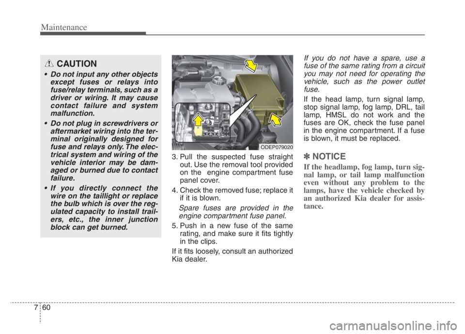
3. Pull the suspected fuse straight
out. Use the removal tool provided
on the engine compartment fuse
panel cover.
4. Check the removed fuse; replace it
if it is blown.
Spare fuses are provided in the
engine compartment fuse panel.
5. Push in a new fuse of the same
rating, and make sure it fits tightly
in the clips.
If it fits loosely, consult an authorized
Kia dealer.
If you do not have a spare, use a
fuse of the same rating from a circuit
you may not need for operating the
vehicle, such as the power outlet
fuse.
If the head lamp, turn signal lamp,
stop signal lamp, fog lamp, DRL, tail
lamp, HMSL do not work and the
fuses are OK, check the fuse panel
in the engine compartment. If a fuse
is blown, it must be replaced.
✽ ✽
NOTICE
If the headlamp, fog lamp, turn sig-
nal lamp, or tail lamp malfunction
even without any problem to the
lamps, have the vehicle checked by
an authorized Kia dealer for assis-
tance.
ODEP079020
CAUTION
Do not input any other objects
except fuses or relays into
fuse/relay terminals, such as a
driver or wiring. It may cause
contact failure and system
malfunction.
Do not plug in screwdrivers or
aftermarket wiring into the ter-
minal originally designed for
fuse and relays only. The elec-
trical system and wiring of the
vehicle interior may be dam-
aged or burned due to contact
failure.
If you directly connect the
wire on the taillight or replace
the bulb which is over the reg-
ulated capacity to install trail-
ers, etc., the inner junction
block can get burned.
Page 631 of 710
767
Maintenance
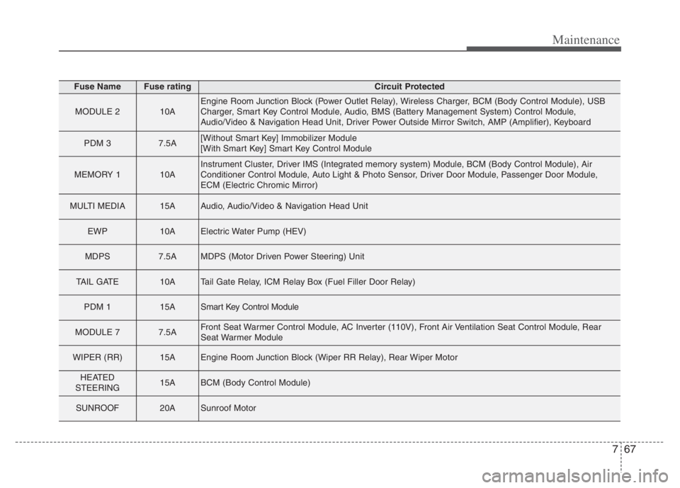
Fuse NameFuse ratingCircuit Protected
MODULE 210AEngine Room Junction Block (Power Outlet Relay), Wireless Charger, BCM (Body Control Module), USB
Charger, Smart Key Control Module, Audio, BMS (Battery Management System) Control Module,
Audio/Video & Navigation Head Unit, Driver Power Outside Mirror Switch, AMP (Amplifier), Keyboard
PDM 37.5A[Without Smart Key] Immobilizer Module
[With Smart Key] Smart Key Control Module
MEMORY 110AInstrument Cluster, Driver IMS (Integrated memory system) Module, BCM (Body Control Module), Air
Conditioner Control Module, Auto Light & Photo Sensor, Driver Door Module, Passenger Door Module,
ECM (Electric Chromic Mirror)
MULTI MEDIA15AAudio, Audio/Video & Navigation Head Unit
EWP10AElectric Water Pump (HEV)
MDPS7.5AMDPS (Motor Driven Power Steering) Unit
TAIL GATE10ATail Gate Relay, ICM Relay Box (Fuel Filler Door Relay)
PDM 115ASmart Key Control Module
MODULE 77.5AFront Seat Warmer Control Module, AC Inverter (110V), Front Air Ventilation Seat Control Module, Rear
Seat Warmer Module
WIPER (RR)15AEngine Room Junction Block (Wiper RR Relay), Rear Wiper Motor
HEATED
STEERING15ABCM (Body Control Module)
SUNROOF20ASunroof Motor