engine KIA NIRO PHEV 2021 Owners Manual
[x] Cancel search | Manufacturer: KIA, Model Year: 2021, Model line: NIRO PHEV, Model: KIA NIRO PHEV 2021Pages: 710, PDF Size: 14.77 MB
Page 641 of 710
777
Maintenance
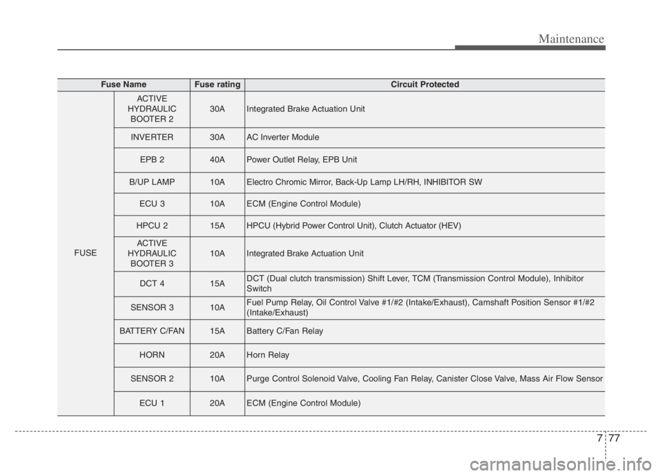
Fuse NameFuse ratingCircuit Protected
FUSE
ACTIVE
HYDRAULIC
BOOTER 230AIntegrated Brake Actuation Unit
INVERTER30AAC Inverter Module
EPB 240APower Outlet Relay, EPB Unit
B/UP LAMP10AElectro Chromic Mirror, Back-Up Lamp LH/RH, INHIBITOR SW
ECU 310AECM (Engine Control Module)
HPCU 215AHPCU (Hybrid Power Control Unit), Clutch Actuator (HEV)
ACTIVE
HYDRAULIC
BOOTER 310AIntegrated Brake Actuation Unit
DCT 415ADCT (Dual clutch transmission) Shift Lever, TCM (Transmission Control Module), Inhibitor
Switch
SENSOR 310AFuel Pump Relay, Oil Control Valve #1/#2 (Intake/Exhaust), Camshaft Position Sensor #1/#2
(Intake/Exhaust)
BATTERY C/FAN15ABattery C/Fan Relay
HORN20AHorn Relay
SENSOR 210APurge Control Solenoid Valve, Cooling Fan Relay, Canister Close Valve, Mass Air Flow Sensor
ECU 120AECM (Engine Control Module)
Page 642 of 710
Maintenance
78 7
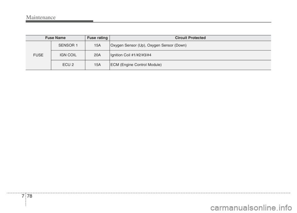
Fuse NameFuse ratingCircuit Protected
FUSE
SENSOR 115AOxygen Sensor (Up), Oxygen Sensor (Down)
IGN COIL20AIgnition Coil #1/#2/#3/#4
ECU 215AECM (Engine Control Module)
Page 643 of 710
779
Maintenance
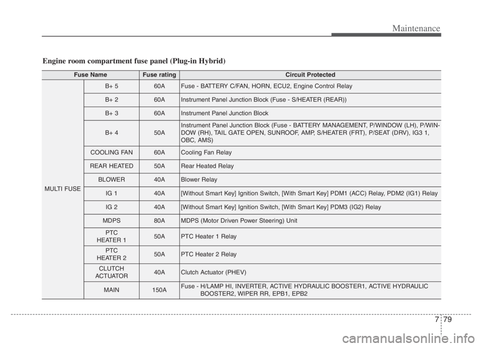
Engine room compartment fuse panel (Plug-in Hybrid)
Fuse NameFuse ratingCircuit Protected
MULTI FUSE
B+ 560AFuse - BATTERY C/FAN, HORN, ECU2, Engine Control Relay
B+ 260AInstrument Panel Junction Block (Fuse - S/HEATER (REAR))
B+ 360AInstrument Panel Junction Block
B+ 450AInstrument Panel Junction Block (Fuse - BATTERY MANAGEMENT, P/WINDOW (LH), P/WIN-
DOW (RH), TAIL GATE OPEN, SUNROOF, AMP, S/HEATER (FRT), P/SEAT (DRV), IG3 1,
OBC, AMS)
COOLING FAN60ACooling Fan Relay
REAR HEATED50ARear Heated Relay
BLOWER40ABlower Relay
IG 140A[Without Smart Key] Ignition Switch, [With Smart Key] PDM1 (ACC) Relay, PDM2 (IG1) Relay
IG 240A[Without Smart Key] Ignition Switch, [With Smart Key] PDM3 (IG2) Relay
MDPS80AMDPS (Motor Driven Power Steering) Unit
PTC
HEATER 150APTC Heater 1 Relay
PTC
HEATER 250APTC Heater 2 Relay
CLUTCH
ACTUATOR40AClutch Actuator (PHEV)
MAIN150AFuse - H/LAMP HI, INVERTER, ACTIVE HYDRAULIC BOOSTER1, ACTIVE HYDRAULIC
BOOSTER2, WIPER RR, EPB1, EPB2
Page 644 of 710
Maintenance
80 7
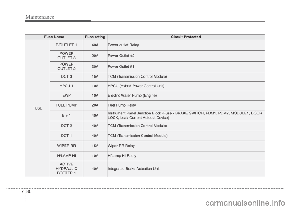
Fuse NameFuse ratingCircuit Protected
FUSE
P/OUTLET 140APower outlet Relay
POWER
OUTLET 320APower Outlet #2
POWER
OUTLET 220APower Outlet #1
DCT 315ATCM (Transmission Control Module)
HPCU 110AHPCU (Hybrid Power Control Unit)
EWP10AElectric Water Pump (Engine)
FUEL PUMP20AFuel Pump Relay
B + 140AInstrument Panel Junction Block (Fuse - BRAKE SWITCH, PDM1, PDM2, MODULE1, DOOR
LOCK, Leak Current Autocut Device)
DCT 240ATCM (Transmission Control Module)
DCT 140ATCM (Transmission Control Module)
WIPER RR15AWiper RR Relay
H/LAMP HI10AH/Lamp HI Relay
ACTIVE
HYDRAULIC
BOOTER 140AIntegrated Brake Actuation Unit
Page 645 of 710
781
Maintenance
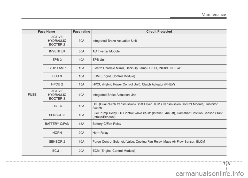
Fuse NameFuse ratingCircuit Protected
FUSE
ACTIVE
HYDRAULIC
BOOTER 230AIntegrated Brake Actuation Unit
INVERTER30AAC Inverter Module
EPB 240AEPB Unit
B/UP LAMP10AElectro Chromic Mirror, Back-Up Lamp LH/RH, INHIBITOR SW
ECU 310AECM (Engine Control Module)
HPCU 215AHPCU (Hybrid Power Control Unit), Clutch Actuator (PHEV)
ACTIVE
HYDRAULIC
BOOTER 310AIntegrated Brake Actuation Unit
DCT 415ADCT(Dual clutch transmission) Shift Lever, TCM (Transmission Control Module), Inhibitor
Switch
SENSOR 310AFuel Pump Relay, Oil Control Valve #1/#2 (Intake/Exhaust), Camshaft Position Sensor #1/#2
(Intake/Exhaust)
BATTERY C/FAN15ABattery C/Fan Relay
HORN20AHorn Relay
SENSOR 210APurge Control Solenoid Valve, Cooling Fan Relay, Mass Air Flow Sensor, ELCM
ECU 120AECM (Engine Control Module)
Page 646 of 710
Maintenance
82 7
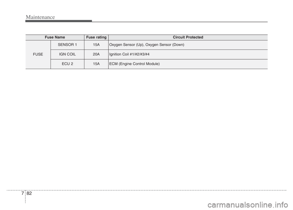
Fuse NameFuse ratingCircuit Protected
FUSE
SENSOR 115AOxygen Sensor (Up), Oxygen Sensor (Down)
IGN COIL20AIgnition Coil #1/#2/#3/#4
ECU 215AECM (Engine Control Module)
Page 650 of 710
Maintenance
86 7
LIGHT BULBS
Bulb replacement precaution
Please keep extra bulbs on hand
with appropriate wattage ratings in
case of emergencies.
Refer to “Bulb Wattage” in chapter 8.
When changing lamps, first turn off
the engine at a safe place, firmly
apply the parking brake and detach
the battery’s negative (-) terminal.
Use only bulbs of the specified
wattage.✽ ✽
NOTICE
• If the light bulb or lamp connector
is removed while the lamp is still
on, the fuse box's electronic sys-
tem may log it as a malfunction.
Therefore, a lamp malfunction
incident may be recorded as a
Diagnostic Trouble Code (DTC) in
the fuse box.
• It is normal for an operating lamp
to flicker momentarily. This is due
to a stabilization function of the
vehicle’s electronic control device.
If the lamp lights up normally
after momentarily blinking, then
it is functioning as normal.
However, if the lamp continues to
flicker several times or turns off
completely, there may be an error
in the vehicle’s electronic control
device. Please have the vehicle
checked by an authorized Kia
dealer immediately.
✽ ✽
NOTICE
We recommend that the headlight
aiming be adjusted by an authorized
Kia dealer after an accident or after
the headlight assembly is reinstalled.
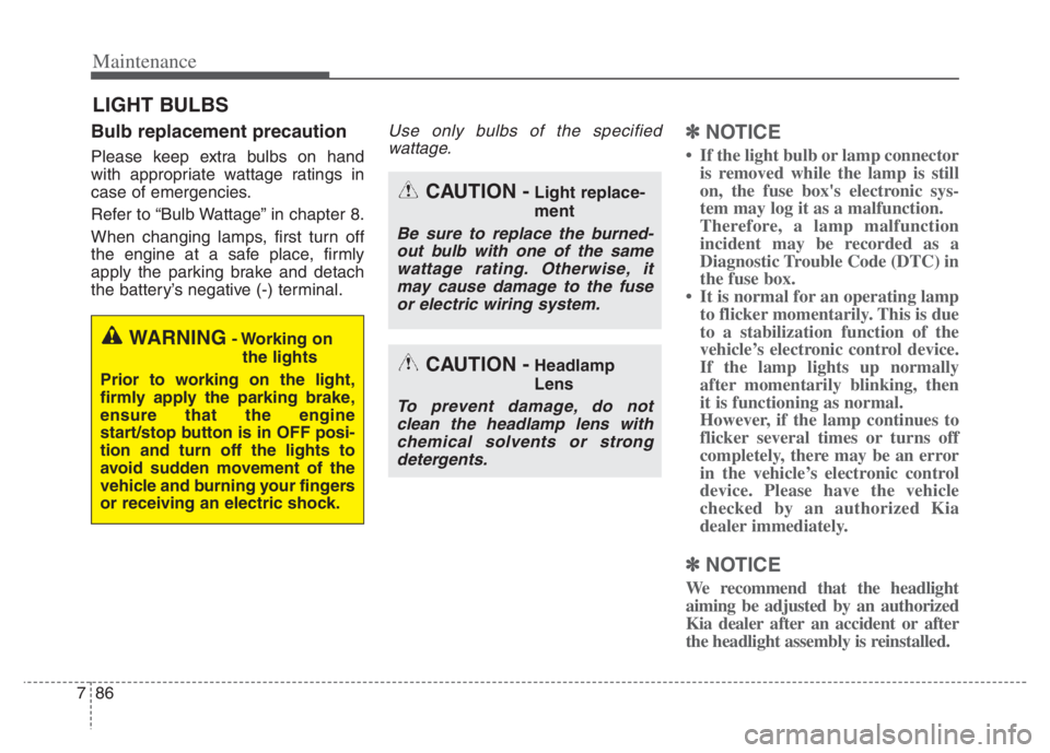
WARNING- Working on
the lights
Prior to working on the light,
firmly apply the parking brake,
ensure that the engine
start/stop button is in OFF posi-
tion and turn off the lights to
avoid sudden movement of the
vehicle and burning your fingers
or receiving an electric shock.
CAUTION -Light replace-
ment
Be sure to replace the burned-
out bulb with one of the same
wattage rating. Otherwise, it
may cause damage to the fuse
or electric wiring system.
CAUTION -Headlamp
Lens
To prevent damage, do not
clean the headlamp lens with
chemical solvents or strong
detergents.
Page 669 of 710
7105
Maintenance
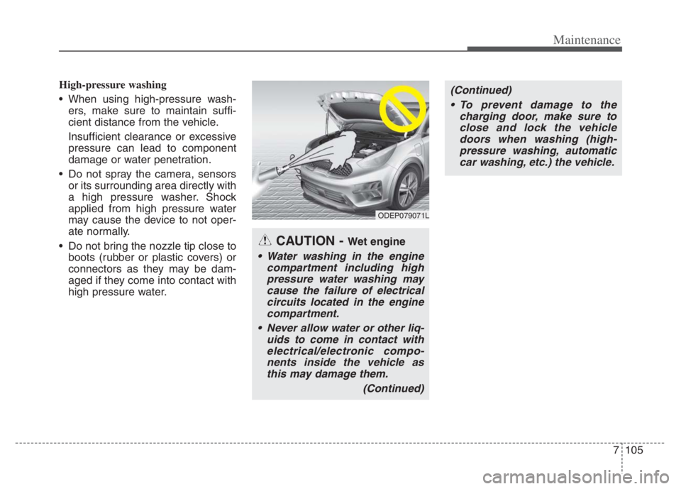
High-pressure washing
When using high-pressure wash-
ers, make sure to maintain suffi-
cient distance from the vehicle.
Insufficient clearance or excessive
pressure can lead to component
damage or water penetration.
Do not spray the camera, sensors
or its surrounding area directly with
a high pressure washer. Shock
applied from high pressure water
may cause the device to not oper-
ate normally.
Do not bring the nozzle tip close to
boots (rubber or plastic covers) or
connectors as they may be dam-
aged if they come into contact with
high pressure water.
ODEP079071L
CAUTION - Wet engine
Water washing in the engine
compartment including high
pressure water washing may
cause the failure of electrical
circuits located in the engine
compartment.
Never allow water or other liq-
uids to come in contact with
electrical/electronic compo-
nents inside the vehicle as
this may damage them.
(Continued)
(Continued)
To prevent damage to the
charging door, make sure to
close and lock the vehicle
doors when washing (high-
pressure washing, automatic
car washing, etc.) the vehicle.
Page 679 of 710
7115
Maintenance
Canister
Fuel vapors generated inside the fuel
tank are absorbed and stored in the
onboard canister. When the engine is
running, the fuel vapors absorbed in
the canister are drawn into the surge
tank through the purge control sole-
noid valve.
Purge Control Solenoid Valve
(PCSV)
The purge control solenoid valve is
controlled by the Engine Control
Module (ECM); when the engine
coolant temperature is low during
idling, the PCSV closes so that evap-
orated fuel is not taken into the
engine. After the engine warms up
during ordinary driving, the PCSV
opens to introduce evaporated fuel to
the engine.
3. Exhaust emission control
system
The Exhaust Emission Control
System is a highly effective system
which controls exhaust emissions
while maintaining good vehicle per-
formance.
Engine exhaust gas precautions
(carbon monoxide)
Carbon monoxide can be present
with other exhaust fumes.
Therefore, if you smell exhaust
fumes of any kind inside your vehi-
cle, have it inspected and repaired
immediately. If you ever suspect
exhaust fumes are coming into
your vehicle, drive it only with all
the windows fully open. Have your
vehicle checked and repaired
immediately.
WARNING - Exhaust
Engine exhaust gases contain
carbon monoxide (CO). Though
colorless and odorless, it is
dangerous and could be lethal if
inhaled. Follow the instructions
on this page to avoid CO poi-
soning.
Page 680 of 710
Maintenance
116 7
Do not operate the engine in con-
fined or closed areas (such as
garages) any more than what is
necessary to move the vehicle in or
out of the area.
When the vehicle is stopped in an
open area for more than a short
time with the engine running,
adjust the ventilation system (as
needed) to draw outside air into the
vehicle.
Never sit in a parked or stopped
vehicle for any extended time with
the engine running.
When the engine stalls or fails to
start, excessive attempts to restart
the engine may cause damage to
the emission control system.Operating precautions for catalyt-
ic converters (if equipped)
WARNING- Catalytic
converter
Keep away from the catalytic
converter and exhaust system
while the vehicle is running or
immediately thereafter. The
exhaust and catalytic systems
are very hot and may burn you.
WARNING- Fire
Do not park, idle or drive the
vehicle over or near flamma-
ble objects, such as grass,
vegetation, paper, leaves, etc.
A hot exhaust system can
ignite flammable items under
your vehicle.
Also, do not remove the heat
sink around the exhaust sys-
tem, do not seal the bottom of
the vehicle and do not coat
the vehicle for corrosion con-
trol. It may present a fire risk
under certain conditions.