brake sensor KIA NIRO PHEV 2021 Owner's Manual
[x] Cancel search | Manufacturer: KIA, Model Year: 2021, Model line: NIRO PHEV, Model: KIA NIRO PHEV 2021Pages: 710, PDF Size: 14.77 MB
Page 538 of 710
What to do in an emergency
18 6
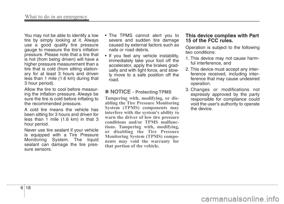
You may not be able to identify a low
tire by simply looking at it. Always
use a good quality tire pressure
gauge to measure the tire's inflation
pressure. Please note that a tire that
is hot (from being driven) will have a
higher pressure measurement than a
tire that is cold (from sitting station-
ary for at least 3 hours and driven
less than 1 mile (1.6 km) during that
3 hour period).
Allow the tire to cool before measur-
ing the inflation pressure. Always be
sure the tire is cold before inflating to
the recommended pressure.
A cold tire means the vehicle has
been sitting for 3 hours and driven for
less than 1 mile (1.6 km) in that 3
hour period.
Never use tire sealant if your vehicle
is equipped with a Tire Pressure
Monitoring System. The liquid
sealant can damage the tire pres-
sure sensors. The TPMS cannot alert you to
severe and sudden tire damage
caused by external factors such as
nails or road debris.
If you feel any vehicle instability,
immediately take your foot off the
accelerator, apply the brakes grad-
ually and with light force, and slow-
ly move to a safe position off the
road.
✽ ✽
NOTICE - Protecting TPMS
Tampering with, modifying, or dis-
abling the Tire Pressure Monitoring
System (TPMS) components may
interfere with the system's ability to
warn the driver of low tire pressure
conditions and/or TPMS malfunc-
tions. Tampering with, modifying,
or disabling the Tire Pressure
Monitoring System (TPMS) compo-
nents may void the warranty for
that portion of the vehicle.
This device complies with Part
15 of the FCC rules.
Operation is subject to the following
two conditions:
1. This device may not cause harm-
ful interference, and
2. This device must accept any inter-
ference received, including inter-
ference that may cause undesired
operation.
3. Changes or modifications not
expressly approved by the party
responsible for compliance could
void the user’s authority to operate
the device.
Page 550 of 710
What to do in an emergency
30 6
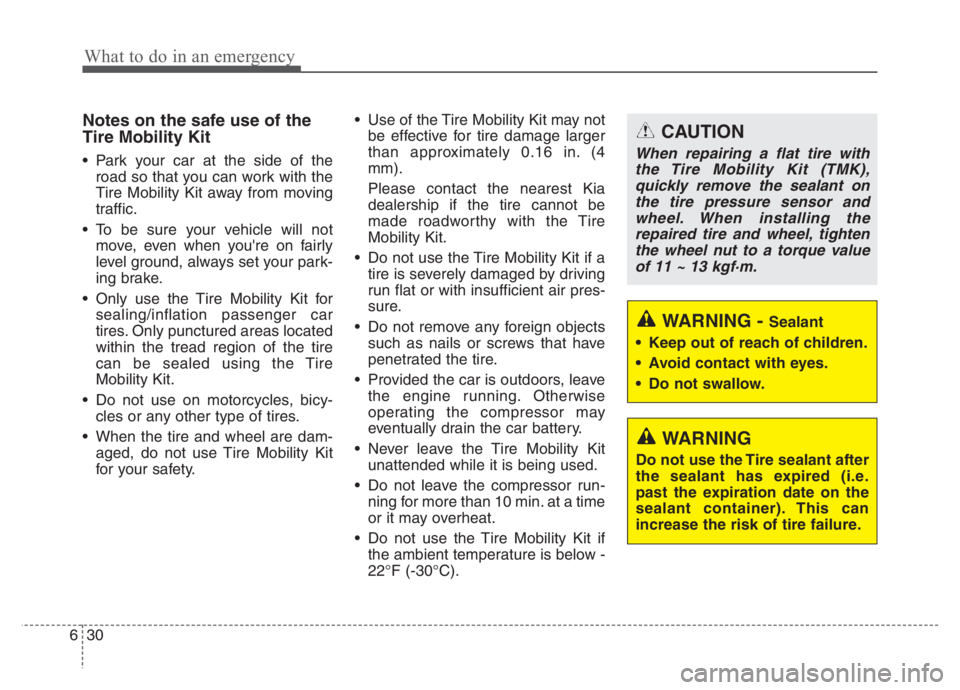
Notes on the safe use of the
Tire Mobility Kit
Park your car at the side of the
road so that you can work with the
Tire Mobility Kit away from moving
traffic.
To be sure your vehicle will not
move, even when you're on fairly
level ground, always set your park-
ing brake.
Only use the Tire Mobility Kit for
sealing/inflation passenger car
tires. Only punctured areas located
within the tread region of the tire
can be sealed using the Tire
Mobility Kit.
Do not use on motorcycles, bicy-
cles or any other type of tires.
When the tire and wheel are dam-
aged, do not use Tire Mobility Kit
for your safety. Use of the Tire Mobility Kit may not
be effective for tire damage larger
than approximately 0.16 in. (4
mm).
Please contact the nearest Kia
dealership if the tire cannot be
made roadworthy with the Tire
Mobility Kit.
Do not use the Tire Mobility Kit if a
tire is severely damaged by driving
run flat or with insufficient air pres-
sure.
Do not remove any foreign objects
such as nails or screws that have
penetrated the tire.
Provided the car is outdoors, leave
the engine running. Otherwise
operating the compressor may
eventually drain the car battery.
Never leave the Tire Mobility Kit
unattended while it is being used.
Do not leave the compressor run-
ning for more than 10 min. at a time
or it may overheat.
Do not use the Tire Mobility Kit if
the ambient temperature is below -
22°F (-30°C).
WARNING
Do not use the Tire sealant after
the sealant has expired (i.e.
past the expiration date on the
sealant container). This can
increase the risk of tire failure.
CAUTION
When repairing a flat tire with
the Tire Mobility Kit (TMK),
quickly remove the sealant on
the tire pressure sensor and
wheel. When installing the
repaired tire and wheel, tighten
the wheel nut to a torque value
of 11 ~ 13 kgf·m.
WARNING - Sealant
Keep out of reach of children.
Avoid contact with eyes.
Do not swallow.
Page 641 of 710
777
Maintenance
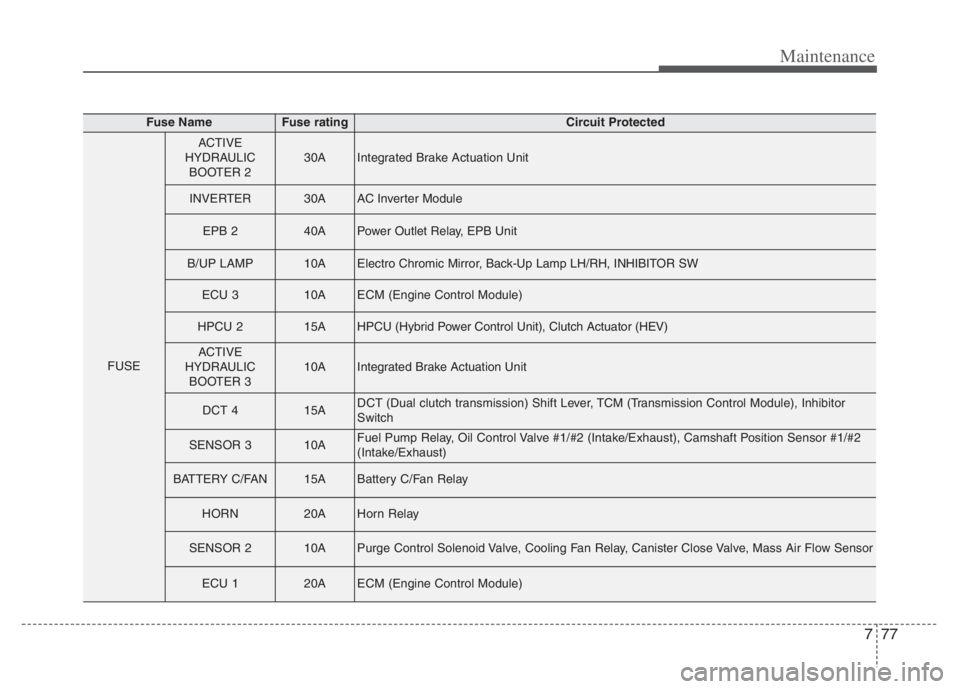
Fuse NameFuse ratingCircuit Protected
FUSE
ACTIVE
HYDRAULIC
BOOTER 230AIntegrated Brake Actuation Unit
INVERTER30AAC Inverter Module
EPB 240APower Outlet Relay, EPB Unit
B/UP LAMP10AElectro Chromic Mirror, Back-Up Lamp LH/RH, INHIBITOR SW
ECU 310AECM (Engine Control Module)
HPCU 215AHPCU (Hybrid Power Control Unit), Clutch Actuator (HEV)
ACTIVE
HYDRAULIC
BOOTER 310AIntegrated Brake Actuation Unit
DCT 415ADCT (Dual clutch transmission) Shift Lever, TCM (Transmission Control Module), Inhibitor
Switch
SENSOR 310AFuel Pump Relay, Oil Control Valve #1/#2 (Intake/Exhaust), Camshaft Position Sensor #1/#2
(Intake/Exhaust)
BATTERY C/FAN15ABattery C/Fan Relay
HORN20AHorn Relay
SENSOR 210APurge Control Solenoid Valve, Cooling Fan Relay, Canister Close Valve, Mass Air Flow Sensor
ECU 120AECM (Engine Control Module)
Page 645 of 710
781
Maintenance
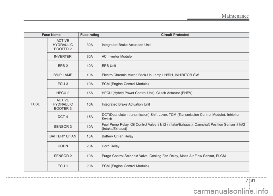
Fuse NameFuse ratingCircuit Protected
FUSE
ACTIVE
HYDRAULIC
BOOTER 230AIntegrated Brake Actuation Unit
INVERTER30AAC Inverter Module
EPB 240AEPB Unit
B/UP LAMP10AElectro Chromic Mirror, Back-Up Lamp LH/RH, INHIBITOR SW
ECU 310AECM (Engine Control Module)
HPCU 215AHPCU (Hybrid Power Control Unit), Clutch Actuator (PHEV)
ACTIVE
HYDRAULIC
BOOTER 310AIntegrated Brake Actuation Unit
DCT 415ADCT(Dual clutch transmission) Shift Lever, TCM (Transmission Control Module), Inhibitor
Switch
SENSOR 310AFuel Pump Relay, Oil Control Valve #1/#2 (Intake/Exhaust), Camshaft Position Sensor #1/#2
(Intake/Exhaust)
BATTERY C/FAN15ABattery C/Fan Relay
HORN20AHorn Relay
SENSOR 210APurge Control Solenoid Valve, Cooling Fan Relay, Mass Air Flow Sensor, ELCM
ECU 120AECM (Engine Control Module)
Page 702 of 710
Index
4I
Dual Clutch Transmission (DCT). . . . . . . . . . . . . . . . . 5-16
Dual clutch transmission operation . . . . . . . . . . . . . 5-16
Good driving practices . . . . . . . . . . . . . . . . . . . . . . . 5-26
Economical operation . . . . . . . . . . . . . . . . . . . . . . . . . 5-182
Electrical Equipment (U.S. only) . . . . . . . . . . . . . . . . . 8-16
Installation of a mobile two-way radio system . . . . 8-16
Emergency starting . . . . . . . . . . . . . . . . . . . . . . . . . . . . . 6-5
Before Jump Starting (For Hybrid) . . . . . . . . . . . . . . 6-5
Jump starting . . . . . . . . . . . . . . . . . . . . . . . . . . . . . . . 6-8
Method to disconnect the (-) cable for regular
maintenance (For Hybrid) . . . . . . . . . . . . . . . . . . . . 6-7
Push-starting . . . . . . . . . . . . . . . . . . . . . . . . . . . . . . . 6-10
Emission control system . . . . . . . . . . . . . . . . . . . . . . . 7-114
Crankcase emission control system . . . . . . . . . . . . 7-114
Evaporative emission control (including ORVR:
Onboard Refueling Vapor Recovery) system. . . . 7-114
Exhaust emission control system . . . . . . . . . . . . . . 7-115
Engine . . . . . . . . . . . . . . . . . . . . . . . . . . . . . . . . . . . . . . 8-2
Engine clutch actuator fluid . . . . . . . . . . . . . . . . . . . . . 7-28
Checking the engine clutch actuator fluid level. . . . 7-28
Engine compartment . . . . . . . . . . . . . . . . . . . . . . . . 2-6, 7-4
Engine number . . . . . . . . . . . . . . . . . . . . . . . . . . . . . . . 8-11
Engine oil . . . . . . . . . . . . . . . . . . . . . . . . . . . . . . . . . . . 7-19
Changing the engine oil and filter . . . . . . . . . . . . . . 7-20
Checking the engine oil level . . . . . . . . . . . . . . . . . . 7-19ENGINE START/STOP button . . . . . . . . . . . . . . . . . . 5-11
ENGINE START/STOP button position . . . . . . . . . 5-11
Illuminated ENGINE START/STOP button . . . . . . 5-11
Starting the hybrid system . . . . . . . . . . . . . . . . . . . . 5-13
Explanation of scheduled maintenance items . . . . . . . 7-15
Exterior features . . . . . . . . . . . . . . . . . . . . . . . . . . . . . 4-176
Roof rack . . . . . . . . . . . . . . . . . . . . . . . . . . . . . . . . 4-176
Exterior overview . . . . . . . . . . . . . . . . . . . . . . . . . . . . . . 2-2
Folding key . . . . . . . . . . . . . . . . . . . . . . . . . . . . . . . . . . . 4-4
Battery replacement . . . . . . . . . . . . . . . . . . . . . . . . . . 4-7
Immobilizer system . . . . . . . . . . . . . . . . . . . . . . . . . . 4-8
Key operations . . . . . . . . . . . . . . . . . . . . . . . . . . . . . . 4-4
Record your key number . . . . . . . . . . . . . . . . . . . . . . 4-4
Transmitter precautions . . . . . . . . . . . . . . . . . . . . . . . 4-6
Forward Collision-Avoidance Assist (FCA)
(Front view camera only) . . . . . . . . . . . . . . . . . . . . . 5-54
Brake operation . . . . . . . . . . . . . . . . . . . . . . . . . . . . 5-58
Detecting sensor (Front view camera) . . . . . . . . . . . 5-59
FCA warning message and function control . . . . . . 5-57
Function malfunction . . . . . . . . . . . . . . . . . . . . . . . . 5-61
Function setting and activation . . . . . . . . . . . . . . . . 5-54
Limitation of the function . . . . . . . . . . . . . . . . . . . . 5-63
Forward Collision-Avoidance Assist (FCA)
(Sensor fusion) . . . . . . . . . . . . . . . . . . . . . . . . . . . . . 5-70
Brake operation . . . . . . . . . . . . . . . . . . . . . . . . . . . . 5-75
E
F