display KIA NIRO PHEV 2021 Manual Online
[x] Cancel search | Manufacturer: KIA, Model Year: 2021, Model line: NIRO PHEV, Model: KIA NIRO PHEV 2021Pages: 710, PDF Size: 14.77 MB
Page 483 of 710
Driving your vehicle
160 5
The vehicle brakes suddenly.
Only one lane marker is detected.
The lane is very wide or narrow.
There are more than two lane
markers on the road (e.g. construc-
tion area).
Radius of a curve is too small.
The vehicle is driven on a steep
incline.
The steering wheel is turned sud-
denly.Automatic speed setting
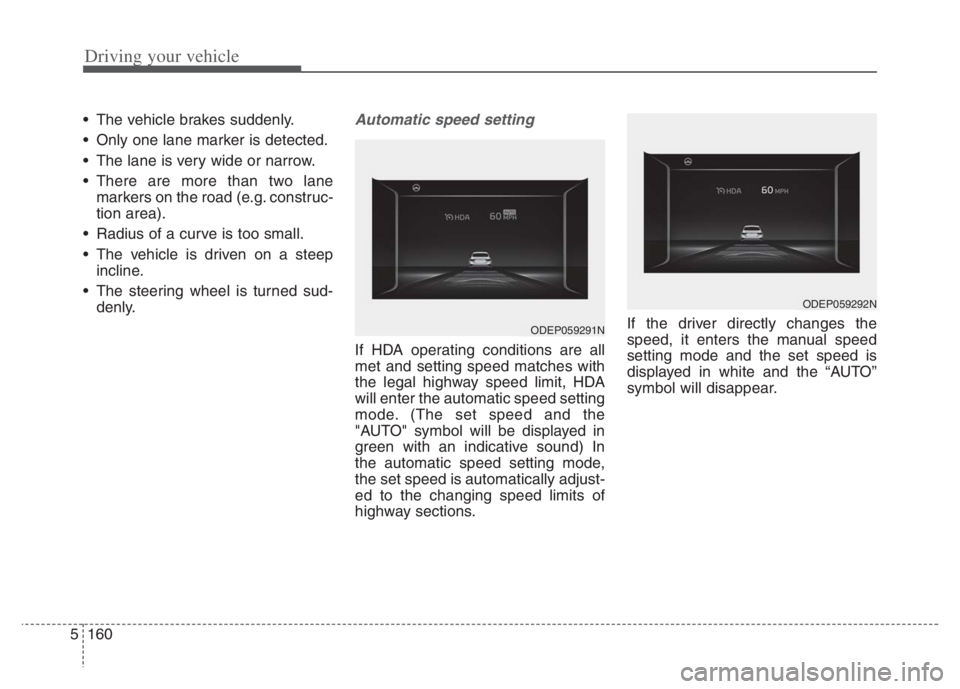
If HDA operating conditions are all
met and setting speed matches with
the legal highway speed limit, HDA
will enter the automatic speed setting
mode. (The set speed and the
"AUTO" symbol will be displayed in
green with an indicative sound) In
the automatic speed setting mode,
the set speed is automatically adjust-
ed to the changing speed limits of
highway sections.If the driver directly changes the
speed, it enters the manual speed
setting mode and the set speed is
displayed in white and the “AUTO”
symbol will disappear.
ODEP059291N
ODEP059292N
Page 489 of 710
Driving your vehicle
166
5
Warning message and func-
tion control
Rear Cross-Traffic Collision
Warning
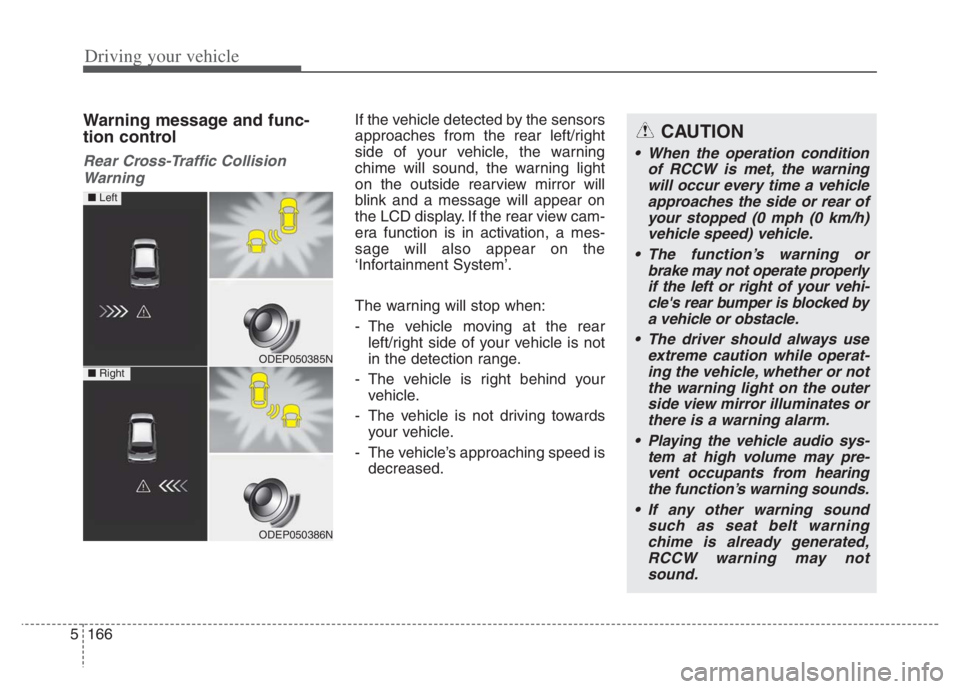
If the vehicle detected by the sensors
approaches from the rear left/right
side of your vehicle, the warning
chime will sound, the warning light
on the outside rearview mirror will
blink and a message will appear on
the LCD display. If the rear view cam-
era function is in activation, a mes-
sage will also appear on the
‘Infortainment System’.
The warning will stop when:
- The vehicle moving at the rear left/right side of your vehicle is not
in the detection range.
- The vehicle is right behind your vehicle.
- The vehicle is not driving towards your vehicle.
- The vehicle’s approaching speed is decreased.CAUTION
• When the operation condition of RCCW is met, the warningwill occur every time a vehicleapproaches the side or rear ofyour stopped (0 mph (0 km/h)vehicle speed) vehicle.
The function’s warning or brake may not operate properlyif the left or right of your vehi-cle's rear bumper is blocked bya vehicle or obstacle.
The driver should always use extreme caution while operat-ing the vehicle, whether or notthe warning light on the outerside view mirror illuminates orthere is a warning alarm.
Playing the vehicle audio sys- tem at high volume may pre-vent occupants from hearingthe function’s warning sounds.
If any other warning sound such as seat belt warningchime is already generated,RCCW warning may notsound.
ODEP050385N
ODEP050386N
■ Left
■ Right
Page 490 of 710
5167
Driving your vehicle
Detecting Sensor
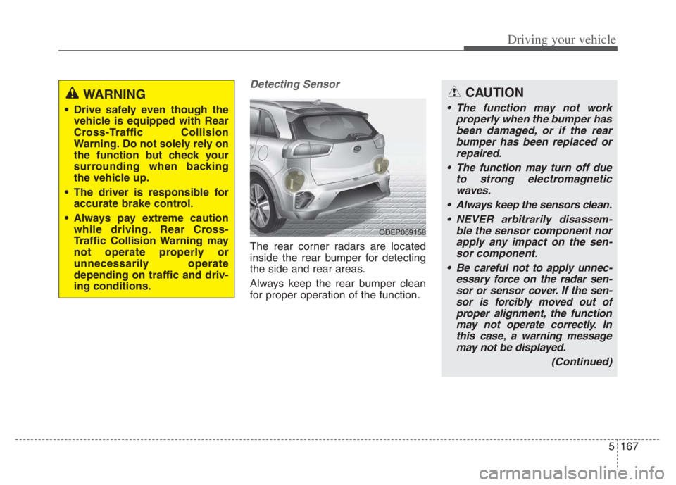
The rear corner radars are located
inside the rear bumper for detecting
the side and rear areas.
Always keep the rear bumper clean
for proper operation of the function.
ODEP059158
CAUTION
The function may not work
properly when the bumper has
been damaged, or if the rear
bumper has been replaced or
repaired.
The function may turn off due
to strong electromagnetic
waves.
Always keep the sensors clean.
NEVER arbitrarily disassem-
ble the sensor component nor
apply any impact on the sen-
sor component.
Be careful not to apply unnec-
essary force on the radar sen-
sor or sensor cover. If the sen-
sor is forcibly moved out of
proper alignment, the function
may not operate correctly. In
this case, a warning message
may not be displayed.
(Continued)
WARNING
Drive safely even though the
vehicle is equipped with Rear
Cross-Traffic Collision
Warning. Do not solely rely on
the function but check your
surrounding when backing
the vehicle up.
The driver is responsible for
accurate brake control.
Always pay extreme caution
while driving. Rear Cross-
Traffic Collision Warning may
not operate properly or
unnecessarily operate
depending on traffic and driv-
ing conditions.
Page 491 of 710
Driving your vehicle
168 5
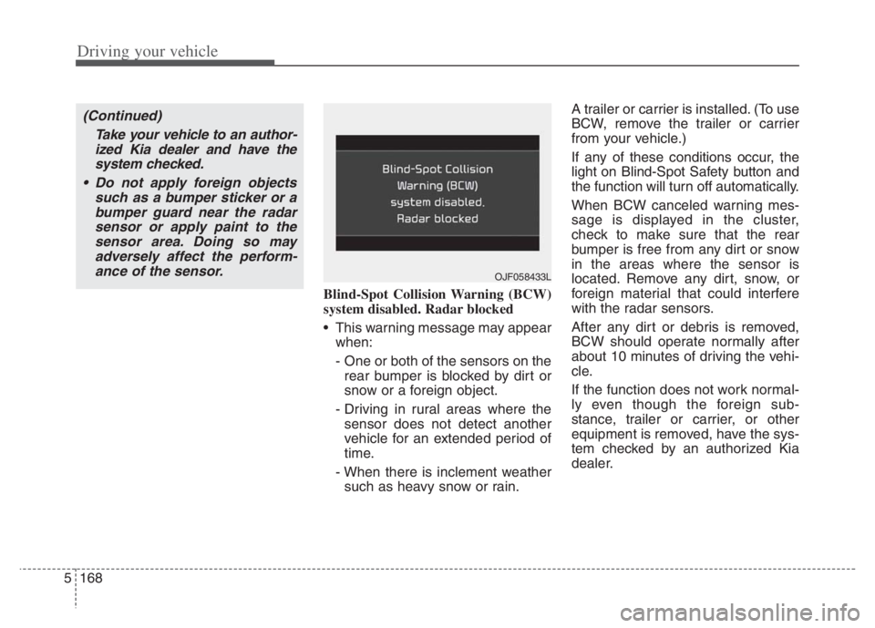
Blind-Spot Collision Warning (BCW)
system disabled. Radar blocked
This warning message may appear
when:
- One or both of the sensors on the
rear bumper is blocked by dirt or
snow or a foreign object.
- Driving in rural areas where the
sensor does not detect another
vehicle for an extended period of
time.
- When there is inclement weather
such as heavy snow or rain.A trailer or carrier is installed. (To use
BCW, remove the trailer or carrier
from your vehicle.)
If any of these conditions occur, the
light on Blind-Spot Safety button and
the function will turn off automatically.
When BCW canceled warning mes-
sage is displayed in the cluster,
check to make sure that the rear
bumper is free from any dirt or snow
in the areas where the sensor is
located. Remove any dirt, snow, or
foreign material that could interfere
with the radar sensors.
After any dirt or debris is removed,
BCW should operate normally after
about 10 minutes of driving the vehi-
cle.
If the function does not work normal-
ly even though the foreign sub-
stance, trailer or carrier, or other
equipment is removed, have the sys-
tem checked by an authorized Kia
dealer.
OJF058433L
(Continued)
Take your vehicle to an author-
ized Kia dealer and have the
system checked.
Do not apply foreign objects
such as a bumper sticker or a
bumper guard near the radar
sensor or apply paint to the
sensor area. Doing so may
adversely affect the perform-
ance of the sensor.
Page 533 of 710
613
What to do in an emergency
TIRE PRESSURE MONITORING SYSTEM (TPMS)
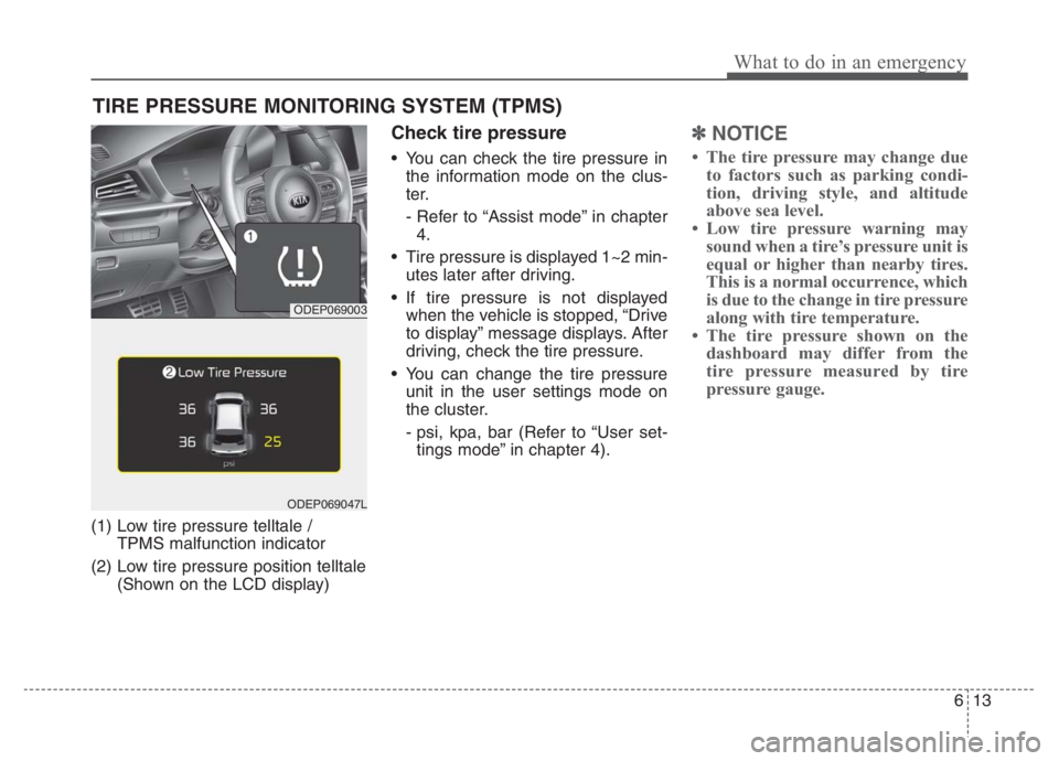
(1) Low tire pressure telltale /
TPMS malfunction indicator
(2) Low tire pressure position telltale
(Shown on the LCD display)
Check tire pressure
You can check the tire pressure in
the information mode on the clus-
ter.
- Refer to “Assist mode” in chapter
4.
Tire pressure is displayed 1~2 min-
utes later after driving.
If tire pressure is not displayed
when the vehicle is stopped, “Drive
to display” message displays. After
driving, check the tire pressure.
You can change the tire pressure
unit in the user settings mode on
the cluster.
- psi, kpa, bar (Refer to “User set-
tings mode” in chapter 4).
✽ ✽
NOTICE
• The tire pressure may change due
to factors such as parking condi-
tion, driving style, and altitude
above sea level.
• Low tire pressure warning may
sound when a tire’s pressure unit is
equal or higher than nearby tires.
This is a normal occurrence, which
is due to the change in tire pressure
along with tire temperature.
• The tire pressure shown on the
dashboard may differ from the
tire pressure measured by tire
pressure gauge.
ODEP069003
ODEP069047L
Page 552 of 710
What to do in an emergency
32 6
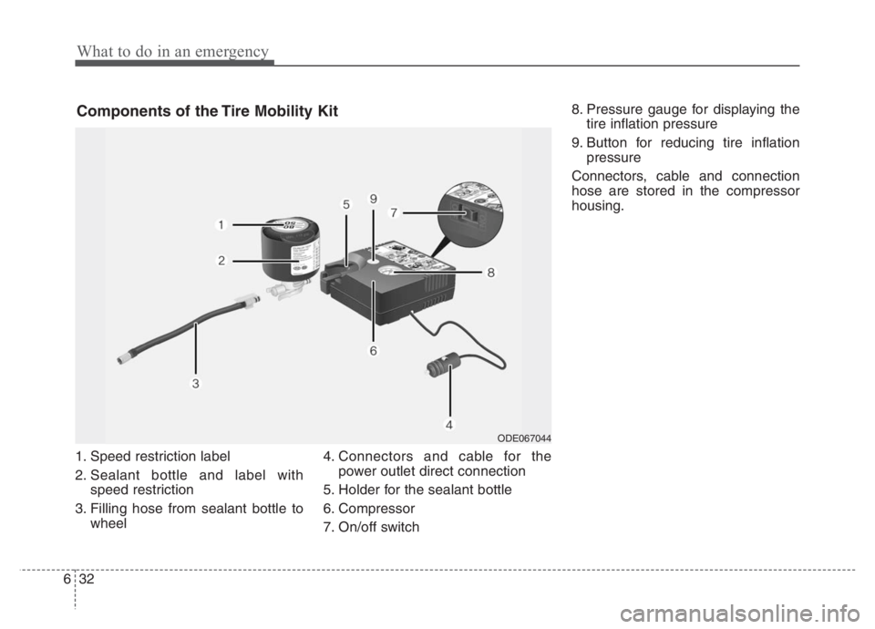
1. Speed restriction label
2. Sealant bottle and label with
speed restriction
3. Filling hose from sealant bottle to
wheel4. Connectors and cable for the
power outlet direct connection
5. Holder for the sealant bottle
6. Compressor
7. On/off switch8. Pressure gauge for displaying the
tire inflation pressure
9. Button for reducing tire inflation
pressure
Connectors, cable and connection
hose are stored in the compressor
housing.
Components of the Tire Mobility Kit
ODE067044
Page 613 of 710
749
Maintenance
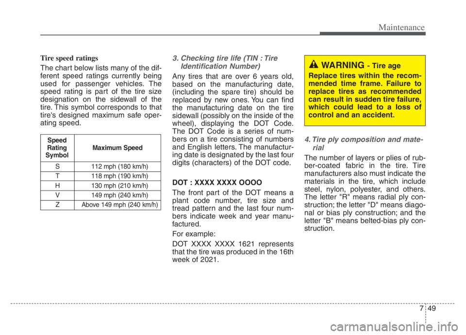
Tire speed ratings
The chart below lists many of the dif-
ferent speed ratings currently being
used for passenger vehicles. The
speed rating is part of the tire size
designation on the sidewall of the
tire. This symbol corresponds to that
tire's designed maximum safe oper-
ating speed.3. Checking tire life (TIN : TireIdentification Number)
Any tires that are over 6 years old,
based on the manufacturing date,
(including the spare tire) should be
replaced by new ones. You can find
the manufacturing date on the tire
sidewall (possibly on the inside of the
wheel), displaying the DOT Code.
The DOT Code is a series of num-
bers on a tire consisting of numbers
and English letters. The manufactur-
ing date is designated by the last four
digits (characters) of the DOT code.
DOT : XXXX XXXX OOOO
The front part of the DOT means a
plant code number, tire size and
tread pattern and the last four num-
bers indicate week and year manu-
factured.
For example:
DOT XXXX XXXX 1621 represents
that the tire was produced in the 16th
week of 2021.
4. Tire ply composition and mate-rial
The number of layers or plies of rub-
ber-coated fabric in the tire. Tire
manufacturers also must indicate the
materials in the tire, which include
steel, nylon, polyester, and others.
The letter "R" means radial ply con-
struction; the letter "D" means diago-
nal or bias ply construction; and the
letter "B" means belted-bias ply con-
struction.
S 112 mph (180 km/h)
T 118 mph (190 km/h)
H 130 mph (210 km/h) V 149 mph (240 km/h)Z Above 149 mph (240 km/h)
Maximum Speed
Speed
Rating
Symbol
WARNING - Tire age
Replace tires within the recom-
mended time frame. Failure to
replace tires as recommended
can result in sudden tire failure,
which could lead to a loss of
control and an accident.
Page 623 of 710

759
Maintenance
✽ ✽
NOTICE
• When replacing fuse, turn the
ignition “OFF” and turn off
switches of all electrical devices
then remove battery (-) terminal.
• The actual fuse/relay panel label
may differ from equipped items.
Inner panel fuse replacement
1. Turn the engine start/stop button
to the OFF position and all other
switches off.
2. Open the fuse panel cover.
If the switch is located in the “OFF”
position, a caution indicator will be
displayed in the cluster.
WARNING- Electrical Fire
Always ensure replacements
fuses and relays are securely
fastened when installed. Failure
to do so can result in a vehicle
fire.
CAUTION
When replacing a blown fuse
or relay, make sure the new
fuse or relay fits tightly into
the clips. Failure to tightly
install the fuse or relay may
cause damage to the wiring
and electric systems.
Do not remove fuses, relays
and terminals fastened with
bolts or nuts. The fuses, relays
and terminals may not be fas-
tened correctly which may
cause vehicle damage.
ODEP079017
Page 625 of 710
761
Maintenance
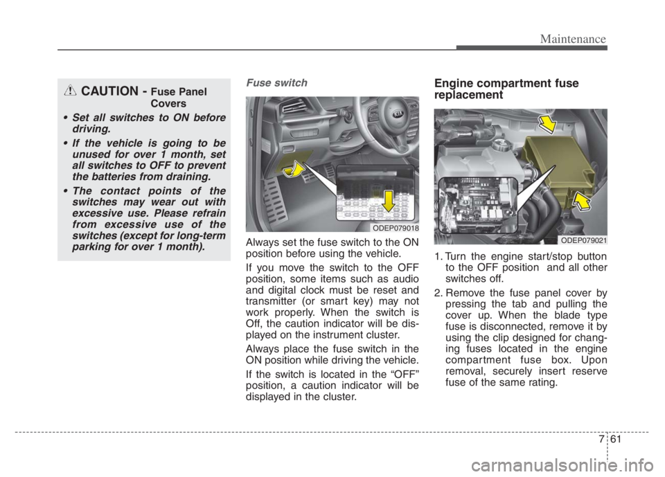
Fuse switch
Always set the fuse switch to the ON
position before using the vehicle.
If you move the switch to the OFF
position, some items such as audio
and digital clock must be reset and
transmitter (or smart key) may not
work properly. When the switch is
Off, the caution indicator will be dis-
played on the instrument cluster.
Always place the fuse switch in the
ON position while driving the vehicle.
If the switch is located in the “OFF”
position, a caution indicator will be
displayed in the cluster.
Engine compartment fuse
replacement
1. Turn the engine start/stop button
to the OFF position and all other
switches off.
2. Remove the fuse panel cover by
pressing the tab and pulling the
cover up. When the blade type
fuse is disconnected, remove it by
using the clip designed for chang-
ing fuses located in the engine
compartment fuse box. Upon
removal, securely insert reserve
fuse of the same rating.
ODEP079018
ODEP079021
CAUTION - Fuse Panel
Covers
Set all switches to ON before
driving.
If the vehicle is going to be
unused for over 1 month, set
all switches to OFF to prevent
the batteries from draining.
The contact points of the
switches may wear out with
excessive use. Please refrain
from excessive use of the
switches (except for long-term
parking for over 1 month).
Page 690 of 710
89
Specifications, Consumer information, Reporting safety defects
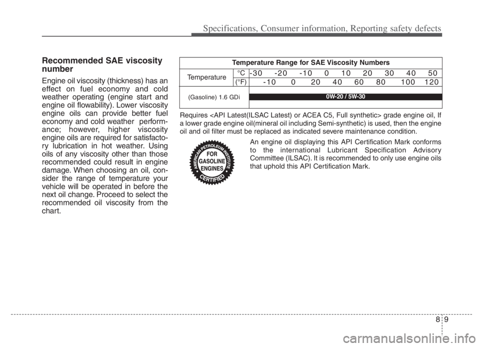
Recommended SAE viscosity
number
Engine oil viscosity (thickness) has an
effect on fuel economy and cold
weather operating (engine start and
engine oil flowability). Lower viscosity
engine oils can provide better fuel
economy and cold weather perform-
ance; however, higher viscosity
engine oils are required for satisfacto-
ry lubrication in hot weather. Using
oils of any viscosity other than those
recommended could result in engine
damage. When choosing an oil, con-
sider the range of temperature your
vehicle will be operated in before the
next oil change. Proceed to select the
recommended oil viscosity from the
chart.
Temperature Range for SAE Viscosity Numbers
Temperature°C
(°F)-30 -20 -10 0 10 20 30 40 50
-10 0 20 40 60 80 100 120
(Gasoline) 1.6 GDi0W-20 / 5W-30
An engine oil displaying this API Certification Mark conforms
to the international Lubricant Specification Advisory
Committee (ILSAC). It is recommended to only use engine oils
that uphold this API Certification Mark. Requires
a lower grade engine oil(mineral oil including Semi-synthetic) is used, then the engine
oil and oil filter must be replaced as indicated severe maintenance condition.