start stop button KIA NIRO PLUG-IN HYBRID 2018 Repair Manual
[x] Cancel search | Manufacturer: KIA, Model Year: 2018, Model line: NIRO PLUG-IN HYBRID, Model: KIA NIRO PLUG-IN HYBRID 2018Pages: 616, PDF Size: 18.98 MB
Page 384 of 616
Driving your vehicle
50
6
Each of these actions will cancel
cruise control operation (the SETindicator light in the instrument clus-ter will go off), but it will not turn thesystem off. If you wish to resumecruise control operation, & you havenot met any of the five (5) cancelmodes, move the lever up (to RES+).You will return to your previously pre-set speed. If you have met one of thefive cancel modes, pressing the(RES+) will set the current speedyour at, & will not resume to the pre-vious memory speed.To resume cruising speed at
more than approximately 20
mph (30 km/h):
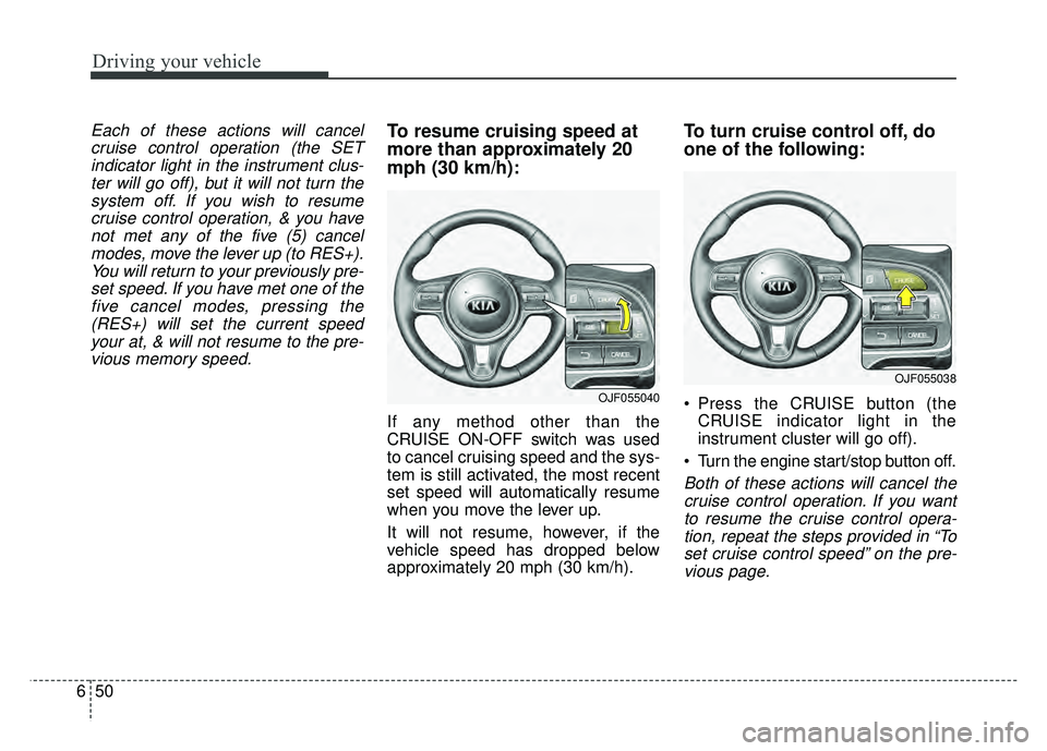
If any method other than the
CRUISE ON-OFF switch was used
to cancel cruising speed and the sys-
tem is still activated, the most recent
set speed will automatically resume
when you move the lever up.
It will not resume, however, if the
vehicle speed has dropped below
approximately 20 mph (30 km/h).
To turn cruise control off, do
one of the following:
Press the CRUISE button (the CRUISE indicator light in the
instrument cluster will go off).
Turn the engine start/stop button off.
Both of these actions will cancel the cruise control operation. If you wantto resume the cruise control opera-tion, repeat the steps provided in “Toset cruise control speed” on the pre-vious page.
OJF055040
OJF055038
Page 401 of 616
667
Driving your vehicle
BSD (Blind Spot Detection) /
LCA (Lane Change Assist)
Operating conditions
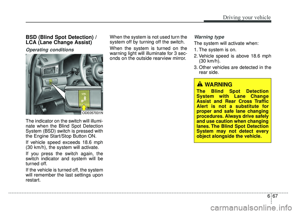
The indicator on the switch will illumi-
nate when the Blind Spot Detection
System (BSD) switch is pressed with
the Engine Start/Stop Button ON.
If vehicle speed exceeds 18.6 mph
(30 km/h), the system will activate.
If you press the switch again, the
switch indicator and system will be
turned off.
If the vehicle is turned off, the system
will remember the last settings upon
restart.When the system is not used turn the
system off by turning off the switch.
When the system is turned on the
warning light will illuminate for 3 sec-
onds on the outside rearview mirror.
Warning type
The system will activate when:
1. The system is on.
2. Vehicle speed is above 18.6 mph
(30 km/h).
3. Other vehicles are detected in the rear side.
WARNING
The Blind Spot Detection
System with Lane Change
Assist and Rear Cross Traffic
Alert is not a substitute for
proper and safe lane changing
procedures. Always drive safely
and use caution when changing
lanes. The Blind Spot Detection
System may not detect every
object alongside the vehicle.
ODE057031N
Page 460 of 616
What to do in an emergency
24
7
6. Ensure that the compressor is
switched off, position 0.
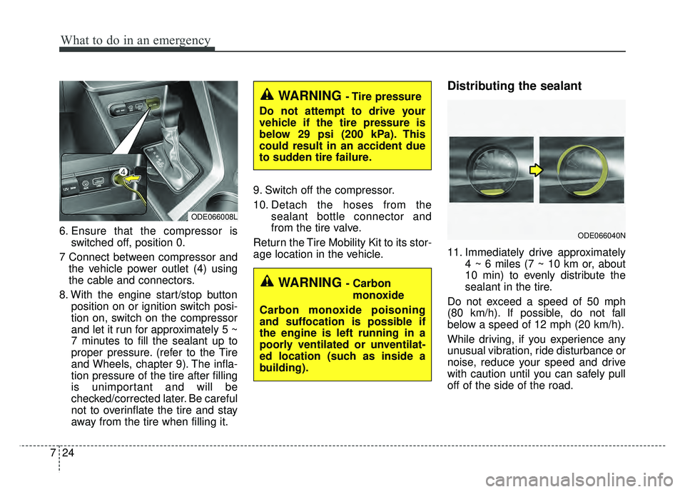
7 Connect between compressor and the vehicle power outlet (4) using
the cable and connectors.
8. With the engine start/stop button position on or ignition switch posi-
tion on, switch on the compressor
and let it run for approximately 5 ~
7 minutes to fill the sealant up to
proper pressure. (refer to the Tire
and Wheels, chapter 9). The infla-
tion pressure of the tire after filling
is unimportant and will be
checked/corrected later. Be careful
not to overinflate the tire and stay
away from the tire when filling it. 9. Switch off the compressor.
10. Detach the hoses from the
sealant bottle connector and
from the tire valve.
Return the Tire Mobility Kit to its stor-
age location in the vehicle.
Distributing the sealant
11. Immediately drive approximately 4 ~ 6 miles (7 ~ 10 km or, about
10 min) to evenly distribute the
sealant in the tire.
Do not exceed a speed of 50 mph
(80 km/h). If possible, do not fall
below a speed of 12 mph (20 km/h).
While driving, if you experience any
unusual vibration, ride disturbance or
noise, reduce your speed and drive
with caution until you can safely pull
off of the side of the road.
ODE066008L
WARNING - Carbon monoxide
Carbon monoxide poisoning
and suffocation is possible if
the engine is left running in a
poorly ventilated or unventilat-
ed location (such as inside a
building).
ODE066040N
WARNING - Tire pressure
Do not attempt to drive your
vehicle if the tire pressure is
below 29 psi (200 kPa). This
could result in an accident due
to sudden tire failure.
Page 533 of 616
Maintenance
64
8
✽
✽
NOTICE
• When replacing fuse, turn the
ignition “OFF” and turn off
switches of all electrical devices
then remove battery (-) terminal.
• The actual fuse/relay panel label may differ from equipped items.
Inner panel fuse replacement
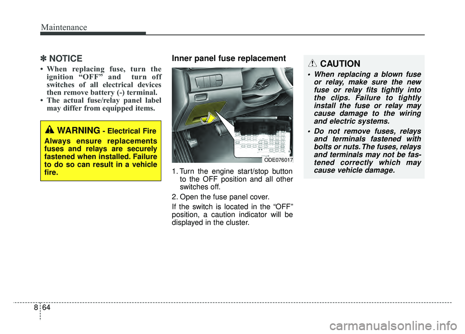
1. Turn the engine start/stop button
to the OFF position and all other
switches off.
2. Open the fuse panel cover.
If the switch is located in the “OFF”
position, a caution indicator will be
displayed in the cluster.
WARNING- Electrical Fire
Always ensure replacements
fuses and relays are securely
fastened when installed. Failure
to do so can result in a vehicle
fire.
CAUTION
When replacing a blown fuse or relay, make sure the newfuse or relay fits tightly intothe clips. Failure to tightlyinstall the fuse or relay maycause damage to the wiringand electric systems.
Do not remove fuses, relays and terminals fastened withbolts or nuts. The fuses, relaysand terminals may not be fas-tened correctly which maycause vehicle damage.
ODE076017
Page 535 of 616
Maintenance
66
8
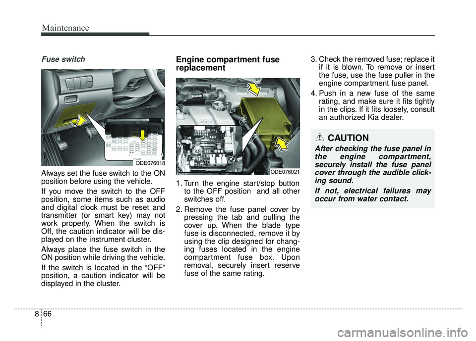
Fuse switch
Always set the fuse switch to the ON
position before using the vehicle.
If you move the switch to the OFF
position, some items such as audio
and digital clock must be reset and
transmitter (or smart key) may not
work properly. When the switch is
Off, the caution indicator will be dis-
played on the instrument cluster.
Always place the fuse switch in the
ON position while driving the vehicle.
If the switch is located in the “OFF”
position, a caution indicator will be
displayed in the cluster.
Engine compartment fuse
replacement
1. Turn the engine start/stop button
to the OFF position and all other
switches off.
2. Remove the fuse panel cover by pressing the tab and pulling the
cover up. When the blade type
fuse is disconnected, remove it by
using the clip designed for chang-
ing fuses located in the engine
compartment fuse box. Upon
removal, securely insert reserve
fuse of the same rating. 3. Check the removed fuse; replace it
if it is blown. To remove or insert
the fuse, use the fuse puller in the
engine compartment fuse panel.
4. Push in a new fuse of the same rating, and make sure it fits tightly
in the clips. If it fits loosely, consult
an authorized Kia dealer.
CAUTION
After checking the fuse panel inthe engine compartment,securely install the fuse panelcover through the audible click-ing sound.
If not, electrical failures mayoccur from water contact.
ODE076018
ODE076021
Page 542 of 616
873
Maintenance
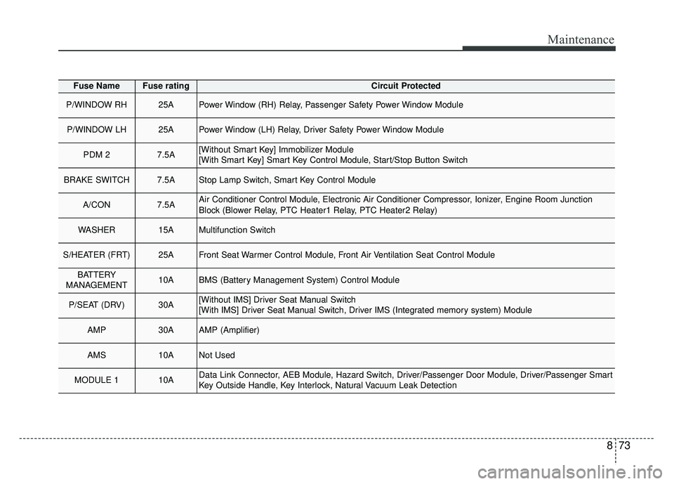
Fuse NameFuse ratingCircuit Protected
P/WINDOW RH25APower Window (RH) Relay, Passenger Safety Power Window Module
P/WINDOW LH25APower Window (LH) Relay, Driver Safety Power Window Module
PDM 27.5A[Without Smart Key] Immobilizer Module
[With Smart Key] Smart Key Control Module, Start/Stop Button Switch
BRAKE SWITCH7.5AStop Lamp Switch, Smart Key Control Module
A/CON7.5AAir Conditioner Control Module, Electronic Air Conditioner Compressor, Ionizer, Engine Room Junction
Block (Blower Relay, PTC Heater1 Relay, PTC Heater2 Relay)
WASHER15AMultifunction Switch
S/HEATER (FRT)25AFront Seat Warmer Control Module, Front Air Ventilation Seat Control Module
BATTERY
MANAGEMENT10ABMS (Battery Management System) Control Module
P/SEAT (DRV)30A[Without IMS] Driver Seat Manual Switch
[With IMS] Driver Seat Manual Switch, Driver IMS (Integrated memory system) Module
AMP30AAMP (Amplifier)
AMS10ANot Used
MODULE 110AData Link Connector, AEB Module, Hazard Switch, Driver/Passenger Door Module, Driver/Passenger Smart
Key Outside Handle, Key Interlock, Natural Vacuum Leak Detection
Page 546 of 616
877
Maintenance
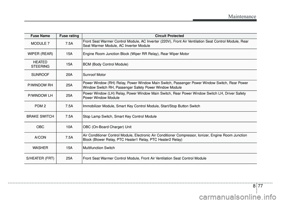
Fuse NameFuse ratingCircuit Protected
MODULE 77.5AFront Seat Warmer Control Module, AC Inverter (220V), Front Air Ventilation Seat Control Module, Rear
Seat Warmer Module, AC Inverter Module
WIPER (REAR)15AEngine Room Junction Block (Wiper RR Relay), Rear Wiper Motor
HEATED
STEERING15ABCM (Body Control Module)
SUNROOF20ASunroof Motor
P/WINDOW RH25APower Window (RH) Relay, Power Window Main Switch, Passenger Power Window Switch, Rear Power
Window Switch RH, Passenger Safety Power Window Module
P/WINDOW LH25APower Window (LH) Relay, Power Window Main Switch, Rear Power Window Switch LH, Driver Safety
Power Window Module
PDM 27.5AImmobilizer Module, Smart Key Control Module, Start/Stop Button Switch
BRAKE SWITCH7.5AStop Lamp Switch, Smart Key Control Module
OBC10AOBC (On-Board Charger) Unit
A/CON7.5AAir Conditioner Control Module, Electronic Air Conditioner Compressor, Ionizer, Engine Room Junction
Block (Blower Relay, PTC Heater1 Relay, PTC Heater2 Relay)
WASHER15AMultifunction Switch
S/HEATER (FRT)25AFront Seat Warmer Control Module, Front Air Ventilation Seat Control Module
Page 560 of 616
891
Maintenance
LIGHT BULBS
Bulb replacement precaution
Please keep extra bulbs on hand
with appropriate wattage ratings in
case of emergencies.
Refer to “Bulb Wattage” in chapter 9.
When changing lamps, first turn off
the engine at a safe place, firmly
apply the parking brake and detach
the battery’s negative (-) terminal.
Use only bulbs of the specifiedwattage.✽ ✽ NOTICE
• If the light bulb or lamp connector
is removed while the lamp is still
on, the fuse box's electronic sys-
tem may log it as a malfunction.
Therefore, a lamp malfunction
incident may be recorded as a
Diagnostic Trouble Code (DTC) in
the fuse box.
• It is normal for an operating lamp to flicker momentarily. This is due
to a stabilization function of the
vehicle’s electronic control device.
If the lamp lights up normally
after momentarily blinking, then
it is functioning as normal.
However, if the lamp continues to
flicker several times or turns off
completely, there may be an error
in the vehicle’s electronic control
device. Please have the vehicle
checked by an authorized Kia
dealer immediately.
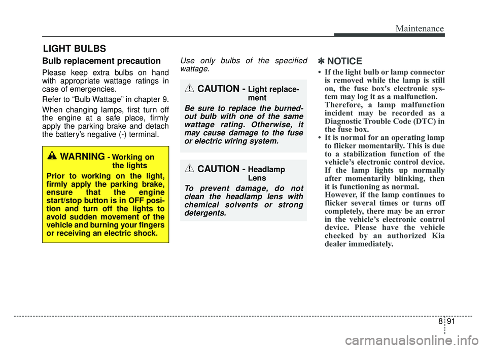
WARNING- Working on
the lights
Prior to working on the light,
firmly apply the parking brake,
ensure that the engine
start/stop button is in OFF posi-
tion and turn off the lights to
avoid sudden movement of the
vehicle and burning your fingers
or receiving an electric shock.
CAUTION -Light replace-
ment
Be sure to replace the burned- out bulb with one of the samewattage rating. Otherwise, itmay cause damage to the fuseor electric wiring system.
CAUTION -Headlamp
Lens
To prevent damage, do notclean the headlamp lens withchemical solvents or strongdetergents.
Page 604 of 616
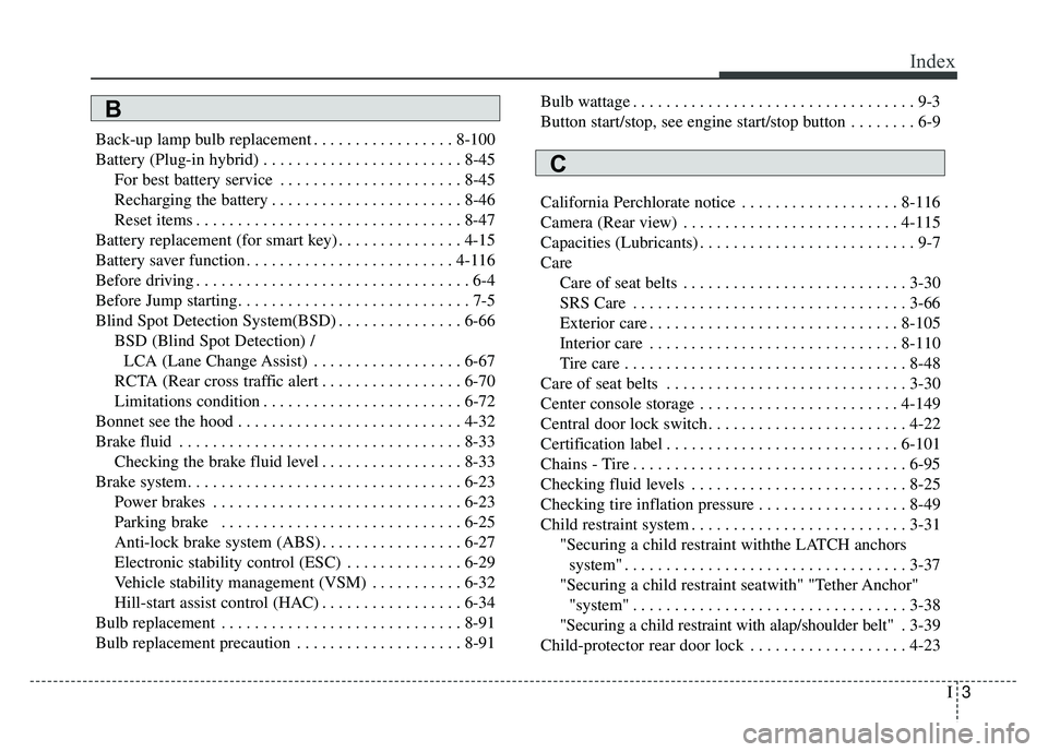
I3
Index
Back-up lamp bulb replacement . . . . . . . . . . . . . . . . . 8-100
Battery (Plug-in hybrid) . . . . . . . . . . . . . . . . . . . . . . . . 8-45For best battery service . . . . . . . . . . . . . . . . . . . . . . 8-45
Recharging the battery . . . . . . . . . . . . . . . . . . . . . . . 8-46
Reset items . . . . . . . . . . . . . . . . . . . . . . . . . . . . . . . . 8-47
Battery replacement (for smart key) . . . . . . . . . . . . . . . 4-15
Battery saver function . . . . . . . . . . . . . . . . . . . . . . . . . 4-116
Before driving . . . . . . . . . . . . . . . . . . . . . . . . . . . . . . . . . 6-4
Before Jump starting. . . . . . . . . . . . . . . . . . . . . . . . . . . . 7-5
Blind Spot Detection System(BSD) . . . . . . . . . . . . . . . 6-66 BSD (Blind Spot Detection) /LCA (Lane Change Assist) . . . . . . . . . . . . . . . . . . 6-67
RCTA (Rear cross traffic alert . . . . . . . . . . . . . . . . . 6-70
Limitations condition . . . . . . . . . . . . . . . . . . . . . . . . 6-72
Bonnet see the hood . . . . . . . . . . . . . . . . . . . . . . . . . . . 4-32
Brake fluid . . . . . . . . . . . . . . . . . . . . . . . . . . . . . . . . . . 8-33\
Checking the brake fluid level . . . . . . . . . . . . . . . . . 8-33
Brake system. . . . . . . . . . . . . . . . . . . . . . . . . . . . . . . . . 6-23 Power brakes . . . . . . . . . . . . . . . . . . . . . . . . . . . . . . 6-23
Parking brake . . . . . . . . . . . . . . . . . . . . . . . . . . . . . 6-25
Anti-lock brake system (ABS) . . . . . . . . . . . . . . . . . 6-27
Electronic stability control (ESC) . . . . . . . . . . . . . . 6-29
Vehicle stability management (VSM) . . . . . . . . . . . 6-32
Hill-start assist control (HAC) . . . . . . . . . . . . . . . . . 6-34
Bulb replacement . . . . . . . . . . . . . . . . . . . . . . . . . . . . . 8-91
Bulb replacement precaution . . . . . . . . . . . . . . . . . . . . 8-91 Bulb wattage . . . . . . . . . . . . . . . . . . . . . . . . . . . . . . . . . . 9-3
Button start/stop, see engine start/stop button . . . . . . . . 6-9
California Perchlorate notice . . . . . . . . . . . . . . . . . . . 8-116
Camera (Rear view) . . . . . . . . . . . . . . . . . . . . . . . . . . 4-115
Capacities (Lubricants) . . . . . . . . . . . . . . . . . . . . . . . . . . 9-7
Care
Care of seat belts . . . . . . . . . . . . . . . . . . . . . . . . . . . 3-30
SRS Care . . . . . . . . . . . . . . . . . . . . . . . . . . . . . . . . . 3-66
Exterior care . . . . . . . . . . . . . . . . . . . . . . . . . . . . . . 8-105
Interior care . . . . . . . . . . . . . . . . . . . . . . . . . . . . . . 8-110
Tire care . . . . . . . . . . . . . . . . . . . . . . . . . . . . . . . . . . 8-48\
Care of seat belts . . . . . . . . . . . . . . . . . . . . . . . . . . . . . 3-30
Center console storage . . . . . . . . . . . . . . . . . . . . . . . . 4-149
Central door lock switch. . . . . . . . . . . . . . . . . . . . . . . . 4-22
Certification label . . . . . . . . . . . . . . . . . . . . . . . . . . . . 6-101
Chains - Tire . . . . . . . . . . . . . . . . . . . . . . . . . . . . . . . . . 6-95
Checking fluid levels . . . . . . . . . . . . . . . . . . . . . . . . . . 8-25
Checking tire inflation pressure . . . . . . . . . . . . . . . . . . 8-49
Child restraint system . . . . . . . . . . . . . . . . . . . . . . . . . . 3-31 "Securing a child restraint withthe LATCH anchors system" . . . . . . . . . . . . . . . . . . . . . . . . . . . . . . . . . . 3-37\
"Securing a child restraint seatwith" "Tether Anchor" "system" . . . . . . . . . . . . . . . . . . . . . . . . . . . . . . . . . 3-38
"Securing a child restraint with alap/shoulder belt" . 3-39
Child-protector rear door lock . . . . . . . . . . . . . . . . . . . 4-23
B
C
Page 606 of 616
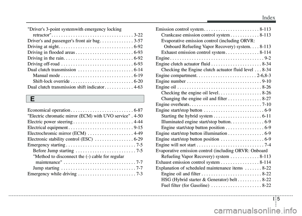
I5
Index
"Driver's 3-point systemwith emergency locking retractor" . . . . . . . . . . . . . . . . . . . . . . . . . . . . . . . . . . 3-22\
Driver's and passenger's front air bag . . . . . . . . . . . . . . 3-57
Driving at night . . . . . . . . . . . . . . . . . . . . . . . . . . . . . . . 6-92
Driving in flooded areas . . . . . . . . . . . . . . . . . . . . . . . . 6-93
Driving in the rain. . . . . . . . . . . . . . . . . . . . . . . . . . . . . 6-92
Driving off-road . . . . . . . . . . . . . . . . . . . . . . . . . . . . . . 6-93
Dual clutch transmission . . . . . . . . . . . . . . . . . . . . . . . 6-14 Manual mode . . . . . . . . . . . . . . . . . . . . . . . . . . . . . . 6-19
Shift-lock override . . . . . . . . . . . . . . . . . . . . . . . . . . 6-20
Dual clutch transmission shift indicator . . . . . . . . . . . . 4-63
Economical operation . . . . . . . . . . . . . . . . . . . . . . . . . . 6-87
"Electric chromatic mirror (ECM) with UVO service" . 4-50
Electric power steering . . . . . . . . . . . . . . . . . . . . . . . . . 4-44
Electrical equipment . . . . . . . . . . . . . . . . . . . . . . . . . . . 9-15
Electrochromic mirror (ECM) . . . . . . . . . . . . . . . . . . . 4-49
Electronic stability control (ESC) . . . . . . . . . . . . . . . . 6-29
Emergency starting . . . . . . . . . . . . . . . . . . . . . . . . . . . . . 7-5 Before Jump starting . . . . . . . . . . . . . . . . . . . . . . . . . 7-5
"Method to disconnect the (-) cable for regular maintenance" . . . . . . . . . . . . . . . . . . . . . . . . . . . . . . 7-7
Jump starting . . . . . . . . . . . . . . . . . . . . . . . . . . . . . . . 7-7
Emergency while driving . . . . . . . . . . . . . . . . . . . . . . . . 7-3 Emission control system . . . . . . . . . . . . . . . . . . . . . . . 8-113
Crankcase emission control system . . . . . . . . . . . . 8-113
Evaporative emission control (including ORVR:Onboard Refueling Vapor Recovery) system. . . . 8-113
Exhaust emission control system . . . . . . . . . . . . . . 8-114
Engine . . . . . . . . . . . . . . . . . . . . . . . . . . . . . . . . . . . . \
. . . 9-2
Engine clutch actuator fluid . . . . . . . . . . . . . . . . . . . . . 8-34 Checking the Engine clutch actuator fluid level . . . 8-34
Engine compartment. . . . . . . . . . . . . . . . . . . . . . . . . 2-6,8-3
Engine number . . . . . . . . . . . . . . . . . . . . . . . . . . . . . . . 9-10
Engine oil . . . . . . . . . . . . . . . . . . . . . . . . . . . . . . . . . . . 8-\
26 Checking the engine oil level . . . . . . . . . . . . . . . . . . 8-26
Changing the engine oil and filter . . . . . . . . . . . . . . 8-27
Engine overheats . . . . . . . . . . . . . . . . . . . . . . . . . . . . . . 7-10
Engine start/stop button . . . . . . . . . . . . . . . . . . . . . . . . . 6-9 Starting the hybrid system . . . . . . . . . . . . . . . . . . . . 6-11
Illuminated engine start/stop button. . . . . . . . . . . . . . 6-9
Engine start/stop button position . . . . . . . . . . . . . . . . 6-9
Engine start/stop button illumination . . . . . . . . . . . . . . . 6-9
Engine start/stop button position . . . . . . . . . . . . . . . . . . 6-9
Engine will not start . . . . . . . . . . . . . . . . . . . . . . . . . . . . 7-4
Evaporative emission control (including ORVR: Onboard Refueling Vapor Recovery) system . . . . . . . . . . . . 8-113
Exhaust emission control system . . . . . . . . . . . . . . . . 8-114
Explanation of scheduled maintenance items . . . . . . . 8-22 Engine oil and filter . . . . . . . . . . . . . . . . . . . . . . . . . 8-22
HSG (Hybrid starter & Generator) belt . . . . . . . . . . 8-22
Fuel filter (for Gasoline) . . . . . . . . . . . . . . . . . . . . . 8-22
E