sensor KIA Opirus 2008 1.G User Guide
[x] Cancel search | Manufacturer: KIA, Model Year: 2008, Model line: Opirus, Model: KIA Opirus 2008 1.GPages: 283, PDF Size: 20.47 MB
Page 80 of 283
Knowing your vehicle
703
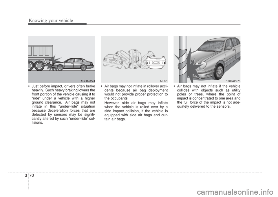
• Just before impact, drivers often brakeheavily. Such heavy braking lowers the
front portion of the vehicle causing it to
“ride” under a vehicle with a higher
ground clearance. Air bags may not
inflate in this "under-ride" situation
because deceleration forces that are
detected by sensors may be signifi-
cantly altered by such “under-ride” col-
lisions. • Air bags may not inflate in rollover acci-
dents because air bag deployment
would not provide proper protection to
the occupants.
However, side air bags may inflate
when the vehicle is rolled over by a
side impact collision, if the vehicle is
equipped with side air bags and cur-
tain air bags. • Air bags may not inflate if the vehicle
collides with objects such as utility
poles or trees, where the point of
impact is concentrated to one area and
the full force of the impact is not ade-
quately delivered to the sensors.
1GHA2274AIR211GHA2275
Page 81 of 283
371
Knowing your vehicle
How does the air bag system
operate
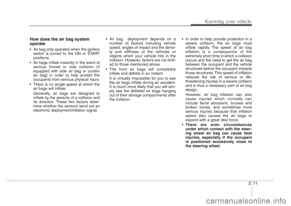
• Air bag only operates when the ignition
switch is turned to the ON or START
positions.
• Air bags inflate instantly in the event of serious frontal or side collision (if
equipped with side air bag or curtain
air bag) in order to help protect the
occupants from serious physical injury.
• There is no single speed at which the air bags will inflate.
Generally, air bags are designed to
inflate by the severity of a collision and
its direction. These two factors deter-
mine whether the sensors send out an
electronic deployment/inflation signal. • Air bag deployment depends on a
number of factors including vehicle
speed, angles of impact and the densi-
ty and stiffness of the vehicles or
objects which your vehicle hits in the
collision. However, factors are not limit-
ed to those mentioned above.
• The front air bags will completely inflate and deflate in an instant.
It is virtually impossible for you to see
the air bags inflate during an accident.
It is much more likely that you will sim-
ply see the deflated air bags hanging
out of their storage compartments after
the collision. • In order to help provide protection in a
severe collision, the air bags must
inflate rapidly. The speed of air bag
inflation is a consequence of the
extremely short time in which a collision
occurs and the need to get the air bag
between the occupant and the vehicle
structures before the occupant impacts
those structures. This speed of inflation
reduces the risk of serious or life-
threatening injuries in a severe collision
and is thus a necessary part of air bag
design.
However, air bag inflation can also
cause injuries which normally can
include facial abrasions, bruises and
broken bones, and sometimes more
serious injuries because that inflation
speed also causes the air bags to
expand with a great deal force.
• There are even circums tances
under which contact with the steer-
ing wheel air bag can cause fatal
injuries,e specially if the occupant
is positioned excessively close to
the steering wheel.
Page 97 of 283
387
Knowing your vehicle
Electric type (if equipped)
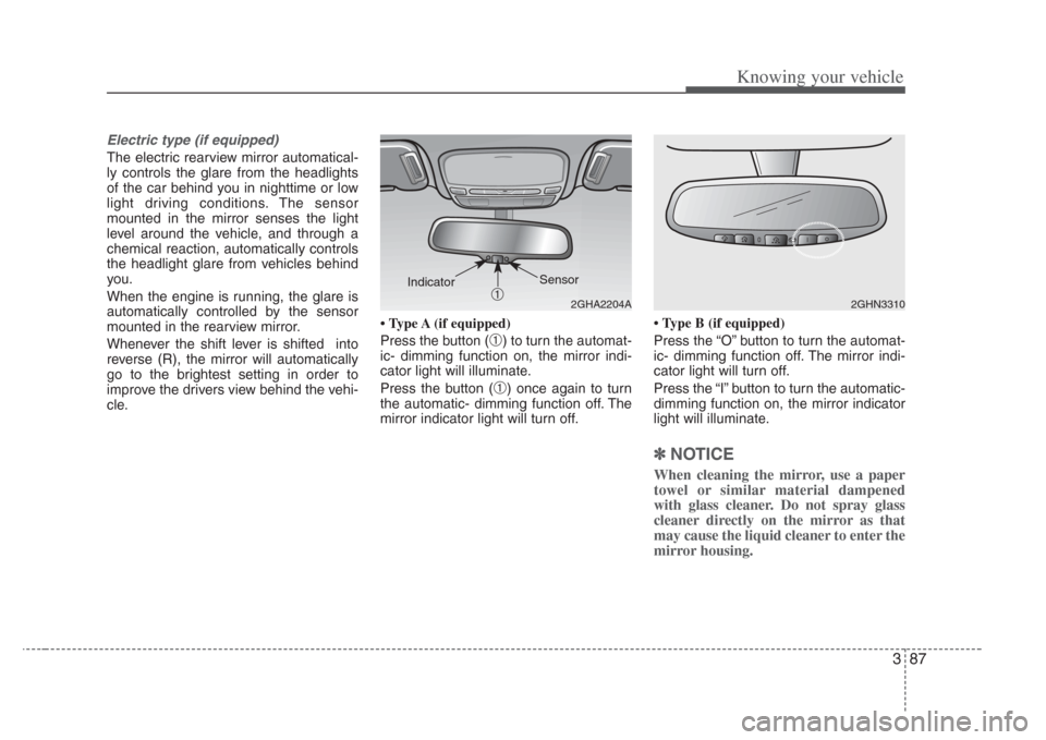
The electric rearview mirror automatical-
ly controls the glare from the headlights
of the car behind you in nighttime or low
light driving conditions. The sensor
mounted in the mirror senses the light
level around the vehicle, and through a
chemical reaction, automatically controls
the headlight glare from vehicles behind
you.
When the engine is running, the glare is
automatically controlled by the sensor
mounted in the rearview mirror.
Whenever the shift lever is shifted into
reverse (R), the mirror will automatically
go to the brightest setting in order to
improve the drivers view behind the vehi-
cle. Type A (if equipped)
Press the button (
➀) to turn the automat-
ic- dimming function on, the mirror indi-
cator light will illuminate.
Press the button (
➀) once again to turn
the automatic- dimming function off. The
mirror indicator light will turn off. Type B (if equipped)
Press the “O” button to turn the automat-
ic- dimming function off. The mirror indi-
cator light will turn off.
Press the “I” button to turn the automatic-
dimming function on, the mirror indicator
light will illuminate.
✽
NOTICE
When cleaning the mirror, use a paper
towel or similar material dampened
with glass cleaner. Do not spray glass
cleaner directly on the mirror as that
may cause the liquid cleaner to enter the
mirror housing.
2GHA2204A
Sensor
➀
Indicator
2GHN3310
Page 129 of 283
![KIA Opirus 2008 1.G User Guide 3119
Knowing your vehicle
✦In the case that you want to
know the distance to fuel
empty (DTE).
Please select the mode of the distance to
fuel empty by adjusting [TRIP] button,
mode transition functi KIA Opirus 2008 1.G User Guide 3119
Knowing your vehicle
✦In the case that you want to
know the distance to fuel
empty (DTE).
Please select the mode of the distance to
fuel empty by adjusting [TRIP] button,
mode transition functi](/img/2/2898/w960_2898-128.png)
3119
Knowing your vehicle
✦In the case that you want to
know the distance to fuel
empty (DTE).
Please select the mode of the distance to
fuel empty by adjusting [TRIP] button,
mode transition function key of concen-
tration key.
[Mode screen of the distance to fuel
empty]
• It displays the possible driving distance
with current fuel level.
• The distance to fuel empty is displayed by 1km unit and if the distance to fuel
empty is less than 50km (30mi.) then '-
--' will flash on the LCD. • If ‘---’ display does not disappear in
fueling, please push TRIP and RESET
button on concentration keys simulta-
neously for more than 5 seconds.
• ‘OFF’ is displayed when fuel sender isn’t connected. • When the actual driving distance is
reduced 1km, the distance to fuel
empty can reduce 2~4km according to
the road condition and fuel efficiency.
✽ NOTICE
Please note that the distance to fuel
empty can change with the driver's driv-
ing habit, road condition and other
causes.
• If fuel sensor makes wrong determina-
tion, feedback algorithm can adjust to
exact possible driving distance.
Flashing
Flashing
Page 153 of 283
Driving your vehicle
224
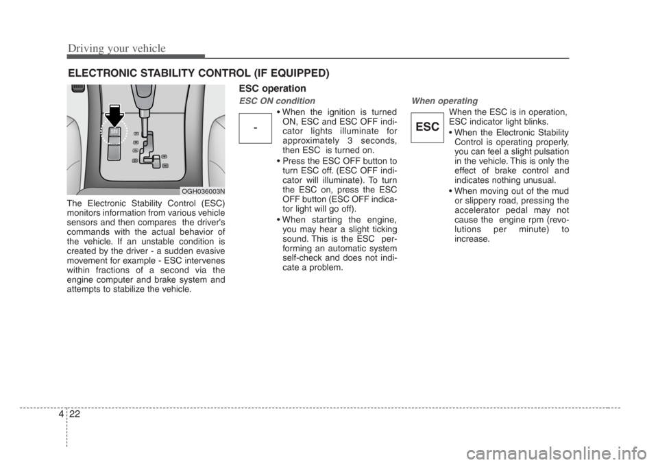
The Electronic Stability Control (ESC)
monitors information from various vehicle
sensors and then compares the driver's
commands with the actual behavior of
the vehicle. If an unstable condition is
created by the driver - a sudden evasive
movement for example - ESC intervenes
within fractions of a second via the
engine computer and brake system and
attempts to stabilize the vehicle.
ESC operation
ESC ON condition
• When the ignition is turnedON, ESC and ESC OFF indi-
cator lights illuminate for
approximately 3 seconds,
then ESC is turned on.
• Press the ESC OFF button to turn ESC off. (ESC OFF indi-
cator will illuminate). To turn
the ESC on, press the ESC
OFF button (ESC OFF indica-
tor light will go off).
• When starting the engine, you may hear a slight ticking
sound. This is the ESC per-
forming an automatic system
self-check and does not indi-
cate a problem.
When operating
When the ESC is in operation,
ESC indicator light blinks.
• When the Electronic StabilityControl is operating properly,
you can feel a slight pulsation
in the vehicle. This is only the
effect of brake control and
indicates nothing unusual.
• When moving out of the mud or slippery road, pressing the
accelerator pedal may not
cause the engine rpm (revo-
lutions per minute) to
increase.
ELECTRONIC STABILITY CONTROL (IF EQUIPPED)
-ESC
OGH036003N
Page 169 of 283
Driving your vehicle
384
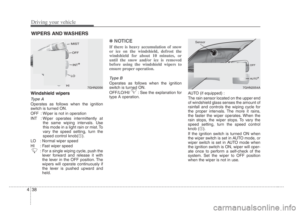
Windshield wipers
Type A
Operates as follows when the ignition
switch is turned ON.
OFF : Wiper is not in operation
INT : Wiper operates intermittently at
the same wiping intervals. Use
this mode in a light rain or mist. To
vary the speed setting, turn the
speed control knob(
➀).
LO : Normal wiper speed
HI : Fast wiper speed : For a single wiping cycle, push thelever forward and release it with
the lever in the OFF position. The
wipers will operate continuously if
the lever is pushed upward and
held.
✽ NOTICE
If there is heavy accumulation of snow
or ice on the windshield, defrost the
windshield for about 10 minutes, or
until the snow and/or ice is removed
before using the windshield wipers to
ensure proper operation.
Type B
Operates as follows when the ignition
switch is turned ON.
OFF/LO/HI/ : See the explanation for
type A operation. AUTO (if equipped) :
The rain sensor located on the upper end
of windshield glass senses the amount of
rainfall and controls the wiping cycle for
the proper intervals. The more it rains,
the faster the wiper operates. When the
rain stops, the wiper stops. To vary the
speed setting, turn the speed control
knob (
➀).
If the ignition switch is turned ON when
the wiper switch is set in AUTO mode, or
wiper switch is set in AUTO mode when
the ignition switch is ON, wiper will oper-
ate once to perform a self-check of the
system. Set the wiper to OFF position
when the wiper is not in use.
WIPERS AND WASHERS
7GHN20567GHN2054A
Sensor
Page 170 of 283
439
Driving your vehicle
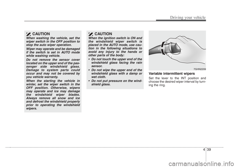
Variable intermittent wipers
Set the lever to the INT position and
choose the desired wiper interval by turn-
ing the ring.
7GHN2209
CAUTION
When the ignition switch is ON and
the winds hield wiper s witch is
placed in the AUTO mode, u se cau-
tion in the following situations to avoid any injury to the hand s or
other parts of the body:
• Do not touch the upper end of the windshield glass facing the rainsensor.
• Do not wipe the upper end of the windshield glass with a damp orwet cloth.
• Do not put pre ssure on the wind-
shield glass.
CAUTION
When washing the vehicle, set the
wiper switch in the OFF po sition to
stop the auto wiper operation.
Wiper may operate and be damagedif the s witch is set in AUTO mode
while washing vehicle.
Do not remove the sensor coverlocated on the upper end of the pa s-
s enger side winds hield glass.
Damage to s ystem parts could
occur and may not be covered by you vehicle warranty.
When the starting the vehicle inwinter, set the wiper s witch in the
OFF pos ition. Otherwis e, wipers
may operate and ice may damage the winds hield wiper blades .
Always remove all snow and ice and defrost the windshield properlyprior to operating the wind shield
wiper s.
Page 175 of 283
Driving your vehicle
444
Automatic operation
The automatic climate control system is
controlled by simply setting the desired
temperature.
The Full Automatic Temperature Control
(FATC) system automatically controls the
heating and cooling system as follows;
1. Push the AUTO button. The indicatorlight will come on and the modes, fan
speeds, air intake and air-conditioning
will be controlled automatically by tem-
perature setting. 2. Push the TEMP button to set the
desired temperature.
If the temperature is set to the lowest
setting 17°C/62°F (Lo), the air condi-
tioning system will operate continu-
ously.
3. To turn the automatic operation off, press any button except temperature
control button. If you press the mode
selection button, air-conditioning but-
ton, defrost button, recirculated air
position button, outside (fresh) air
position button or fan speed button,
the selected function will be controlled
manually while other functions operate
automatically.
Regardless of the temperature setting,
when using automatic operation, the air
conditioning system will automatically
turn on to decrease the humidity inside
the vehicle, even if the temperature is set
to warm.
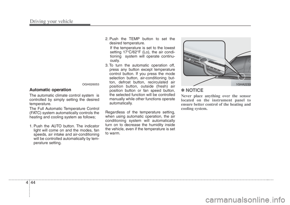
✽ NOTICE
Never place anything over the sensor
located on the instrument panel to
ensure better control of the heating and
cooling system.
OGH0260531GHA2233
Page 209 of 283
525
Driving tips
HOMELINK® WIRELESS CONTROL SYSTEM (IF EQUIPPED)
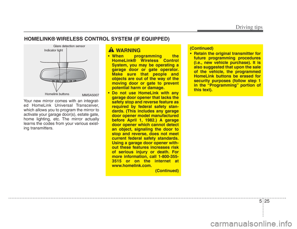
Your new mirror comes with an integrat-
ed HomeLink Universal Transceiver,
which allows you to program the mirror to
activate your garage door(s), estate gate,
home lighting, etc. The mirror actually
learns the codes from your various exist-
ing transmitters.
MMSA5007
Homelink buttons Glare detection sensor
Indicator lightWARNING
• When programming the
HomeLink® Wireless Control
System, you may be operating a
garage door or gate operator.
Make sure that people and
objects are out of the way of the
moving door or gate to prevent
potential harm or damage.
• Do not use HomeLink with any garage door opener that lacks the
safety stop and rever se feature as
required by federal safety stan-
dards. (This includes any garage
door opener model manufactured
before April 1, 1982.) A garage
door opener which cannot detect
an object, signaling the door to
stop and rever se, does not meet
current federal safety standards.
Using a garage door opener with-
out these features increases risk
of serious injury or death. For
more information, call 1-800-355-
3515 or on the internet at
www.homelink.com.
(Continued)
(Continued)
• Retain the original tran smitter for
future programming procedures
(i.e., new vehicle purcha se). It is
also suggested that upon the sale
of the vehicle, the programmed
HomeLink button s be erased for
security purposes (follow step 1
in the “Programming” portion of
this text).
Page 222 of 283
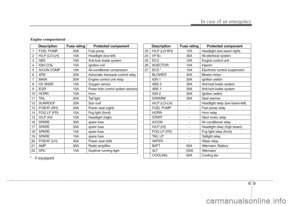
69
In case of an emergency
Description Fus e rating Protected component
1 FUEL PUMP 20A Fuel pump
2 H/LP (LO-LH) 15A Headlight (low-left)
3 ABS 10A Anti-lock brake system
4 IGN COIL 15A Ignition coil
5 A/CON COMP 10A Air-conditioner compressor
6 ATM 20A Automatic transaxle control relay
7 MAIN 20A Engine control unit relay
8 O2 SNSR 15A Oxygen sensor
9 EGR 15A
Power train control system sensors
10 HORN 15A Horn
11 TAIL 20A Tail light
12 SUNROOF 20A Sun roof
13 P/SEAT (RH) 20A Power seat (right)
14 FOG LP (FR) 15A Fog light (front)
15 H/LP (HI) 15A Headlight (high)
16 SPARE 30A spare fuse
17 SPARE 20A spare fuse
18 SPARE 15A spare fuse
19 SPARE 10A spare fuse
20 P/SEAT (LH) 30A Power seat (left)
21 AMP 20A Radio amplifier
22 DRL* 15A Daytime running light
Engine compartment
Description Fus e rating Protected component
23 H/LP (LO-RH) 15A Headlight (low beam-right)
24 I/P B+ 30A All electrical system
25 ECU 10A Engine control unit
26 INJECTOR 10A Injector
27 ECS * 15A Electronic control suspension
BLOWER 40A Blower motor
IGN 1 30A Ignition switch
ABS 2 30A Anti-lock brake system
ABS 1 30A Anti-lock brake system
IGN 2 30A Ignition switch
S/WARM 30A Seat warmer
H/LP (LO-LH) - Headlight relay (low beam-left)
FUEL PUMP - Fuel pump relay
HORN - Horn relay
START - Start motor relay
A/CON - Air conditioner relay
H/LP (HI) - Headlight relay (high beam)
FOG LP (FR) - Fog light relay (front)
TAIL LP - Taillight relay
WIPER - Wiper relay
BATT 60A Alternator, Battery
ALT 150A Alternator
COOLING 60A Cooling fan
* : if equipped