ABS KIA Optima 2006 2.G Owner's Manual
[x] Cancel search | Manufacturer: KIA, Model Year: 2006, Model line: Optima, Model: KIA Optima 2006 2.GPages: 225, PDF Size: 3.77 MB
Page 12 of 225
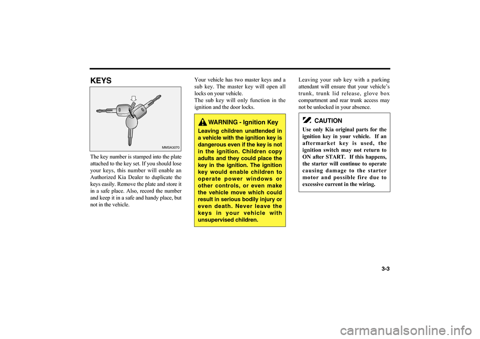
KEYSThe key number is stamped into the plate
attached to the key set. If you should lose
your keys, this number will enable an
Authorized Kia Dealer to duplicate the
keys easily. Remove the plate and store it
in a safe place. Also, record the number
and keep it in a safe and handy place, but
not in the vehicle.Your vehicle has two master keys and a
sub key. The master key will open all
locks on your vehicle.
The sub key will only function in the
ignition and the door locks.Leaving your sub key with a parking
attendant will ensure that your vehicle’s
trunk, trunk lid release, glove box
compartment and rear trunk access may
not be unlocked in your absence.
3-3
50063
MMSA3070
➡ ➡
WARNING - Ignition Key
Leaving children unattended in
a vehicle with the ignition key is
dangerous even if the key is not
in the ignition. Children copy
adults and they could place the
key in the ignition. The ignition
key would enable children to
operate power windows or
other controls, or even make
the vehicle move which could
result in serious bodily injury or
even death. Never leave the
keys in your vehicle with
unsupervised children.
CAUTION
Use only Kia original parts for the
ignition key in your vehicle. If an
aftermarket key is used, the
ignition switch may not return to
ON after START. If this happens,
the starter will continue to operate
causing damage to the starter
motor and possible fire due to
excessive current in the wiring.
MS-CNA-Eng 3.QXD 7/25/2005 5:17 PM Page 3
Page 91 of 225
BRAKE SYSTEMPOWER BRAKESYour vehicle has power-assisted brakes
that adjust automatically through normal
usage.
In the event that brake system power
assist is lost because of a stalled engine
or some other reason, you can still stop
your vehicle by applying greater force to
the brake pedal than you normally
would. The stopping distance, however,
will be longer than usual.
When the engine is not running, the
reserve brake power is partially depleted
each time the brake pedal is depressed.
Do not pump the brake pedal when the
power assist has been interrupted, except
when necessary to maintain steering
control on slippery surfaces.
ANTI LOCK BRAKES (ABS)
(IF EQUIPPED)The anti-lock brake system is designed
to prevent lock-up of the wheels during
sudden braking or braking on slippery
surfaces. Compared to a conventional
brake system, the anti-lock brake system
provides greater steering control during
braking in such situations.DRIVING YOUR VEHICLE
4-12
WARNING - ABS Brakes
The anti-lock brake system
(ABS) cannot compensate for
bad road conditions, for
unsafe or reckless driving or
for bad judgement.
The ABS is designed to
improve maximum braking
effectiveness on typical
highways and roads in good
condition.
On road surfaces which are
in poor condition, the ABS
may actually reduce braking
effectiveness.
Always operate your vehicle
at reasonable speeds that are
safe for weather and traffic
conditions.
MS-CNA-Eng 4(~39).QXD 7/25/2005 5:16 PM Page 12
Page 92 of 225
During normal driving conditions, the
anti-lock brake system operates the same
as a conventional brake system. When
the anti-lock brake system is engaged
due to imminent loss of traction, a
pulsation of the brake pedal will result
and you may hear or feel “chattering”.
This is a normal condition and indicates
the system is functioning properly.
When driving a vehicle equipped with
anti-lock brakes, adjust your driving
according to the road and traffic conditions
and keep the following in mind.
• Do not pump the brakes as you would
when driving a vehicle not equipped
with an anti-lock brake system (ABS).
In order for the ABS to function
normally, press the brake pedal firmly,
without pumping the pedal.
• Even with the anti-lock brake system,
your vehicle still requires a sufficient
stopping distance. Always maintain a
safe distance from the vehicle in
front of you.• Always slow down when cornering.
The anti-lock brake system cannot
prevent accidents resulting from
excessive speeds.
• On loose or uneven road surfaces,
operation of the anti-lock brake
system may result in a longer stopping
distance than for vehicles equipped
with a conventional brake system.
• Avoid high speeds on wet roads. The
anti-lock brake system cannot
eliminate the risk of hydroplaning.
If the anti-lock brake system should fail,
the brake system will function as a
conventional brake system. Have your
vehicle checked by an Authorized Kia
Dealer as soon as possible.
4-13
✻
NOTICE
• If the ABS warning light is on
and stays on, you may have a
problem with the ABS system.
In this case, however, your regu-
lar brakes will work normally.
• The ABS warning light will stay
on for 2-3 seconds after the igni-
tion “ON”. During that time, the
ABS will go through self-diagno-
sis and the light will go off if
everything is normal. If the light
stays on you may have a problem
with your ABS.
Contact an Authorized Kia
Dealer for service as soon as pos-
sible.
MS-CNA-Eng 4(~39).QXD 7/25/2005 5:16 PM Page 13
Page 93 of 225
IN THE EVENT OF BRAKE
FAILUREIf the service brakes should fail to operate
while the vehicle is in motion, you can
make an emergency stop with the parking
brake. The stopping distance, however,
will be much greater than normal.DRIVING YOUR VEHICLE
4-14✻
NOTICE
• If the battery is discharged and
the engine is jump started, the
ABS warning light may come on.
This condition occurs because of
a discharged battery and not
because there is an anti-lock
brake system malfunction.
• Have the battery recharged
before driving the vehicle.
WARNING -
Parking Brake
Pulling on the parking brake
while the vehicle is moving at
normal speed can cause a
sudden loss of control of the
vehicle. If you must use the
parking brake to stop the
vehicle, use great caution in
applying the brake.
WARNING
Do not drive with your foot
resting on the brake pedal.
This will create abnormally
high brake temperatures,
excessive brake lining and
pad wear, and increased
stopping distances.
When descending a long or
steep hill, shift to a lower gear
and avoid continuous applica-
tion of the brakes.
Continuous brake application
will cause the brakes to
overheat and could result in a
temporary loss of braking
performance.
MS-CNA-Eng 4(~39).QXD 7/25/2005 5:16 PM Page 14
Page 105 of 225
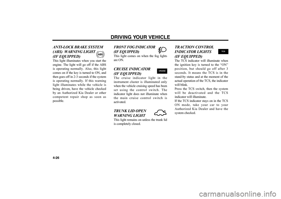
ANTI-LOCK BRAKE SYSTEM
(ABS) WARNING LIGHT
(IF EQUIPPED)This light illuminates when you start the
engine. The light will go off if the ABS
is operating normally. Also, this light
comes on if the key is turned to ON, and
then goes off in 2-3 seconds if the system
is operating normally. If this warning
light illuminates while the vehicle is
being driven, have the vehicle checked
by an Authorized Kia Dealer or other
competent repair shop as soon as
possible.
FRONT FOG INDICATOR
(IF EQUIPPED)This light comes on when the fog lights
are ON.CRUISE INDICATOR
(IF EQUIPPED)The cruise indicator light in the
instrument cluster is illuminated only
when the vehicle cruising speed has been
set using the control switch. The
indicator light does not illuminate when
the main cruise control switch is
activated.TRUNK LID OPEN
WARNING LIGHT This light remains on unless the trunk lid
is completely closed.
TRACTION CONTROL
INDICATOR LIGHTS
(IF EQUIPPED)The TCS indicator will illuminate when
the ignition key is turned to the “ON”
position, but should go off after 3
seconds. It means the TCS is in the
stand-by status and at the moment of the
actual operation of the TCS, the indicator
will blink.
Press the TCS switch, then the system
will be deactivated and the TCS
indicator will illuminate.
If the TCS indicator stays on in the TCS
ON mode, take your car to your
Authorized Kia Dealer and have the
system checked.
DRIVING YOUR VEHICLE
4-26
ABS
CRUISE
TCS
MS-CNA-Eng 4(~39).QXD 7/25/2005 5:16 PM Page 26
Page 163 of 225
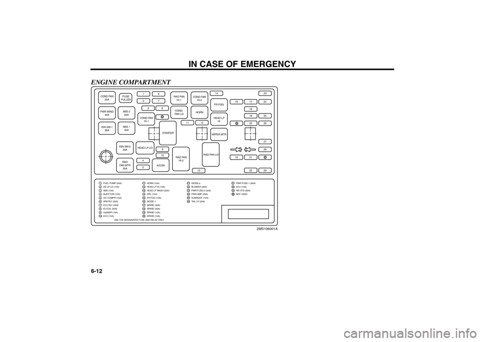
ENGINE COMPARTMENT
IN CASE OF EMERGENCY
6-12
COND FAN
20APWR WIND
40AIGN SW-1
30A
ABS 2
20A FUSE
PULLERABS 1
40A1
COND FAN
HI-1
RAD FAN
HI-1
COND FAN
HI-2
COND
FAN LO
HORN
FR FOGHEAD LP
HIWIPER MTR
STARTER
RAD FAN
HI-2
RAD FAN LO
IGN SW-2
30A
HEAD LP LO
RAD
FAN MTR
30A
A/CON6
2
7
3
8
11
13
14
15
1718
24232728
20
26
16
2122
29
19
25
12
910
45
1 FUEL PUMP (20A)2 HD LP LO (15A)3 ABS (10A)4 INJECTOR (10A)5 A/C COMPR (10A)6 ATM RLY (20A)7 ECU RLY (30A)8 IG COIL (20A)9
10O2SNSR (15A)ECU (15A)
11 HORN (10A)12 HEAD LP HI (15A)13 HEAD LP WASH (20A)14 DRL (15A)15 FR FOG (15A)16 DIODE-1
21
DIODE-222
BLOWER (30A)23
PWR FUSE-2 (30A)24
PWR AMP (20A)
27 PWR FUSE-1 (30A)28 ECU (10A)29 RR HTD (30A)NOT USED
25
SUNROOF (15A)
26
TAIL LP (20A)
17 SPARE (30A)18 SPARE (20A)19 SPARE (15A)20
SPARE (10A)
USE THE DESIGNATED FUSE AND RELAY ONLY
2MS106001A
MS-CNA-Eng 6.QXD 7/25/2005 5:13 PM Page 12
Page 164 of 225
6-13
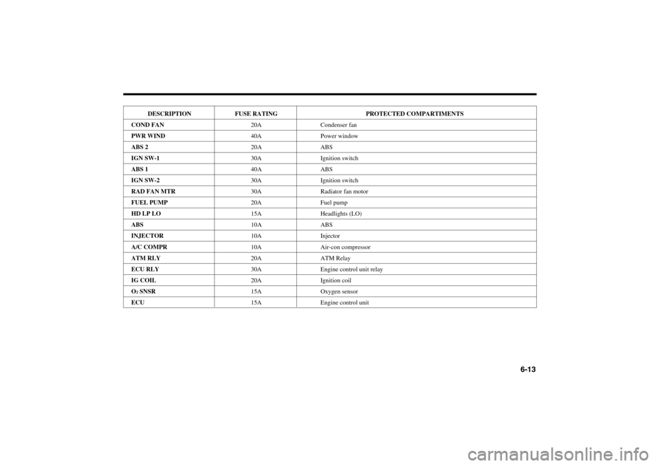
DESCRIPTION FUSE RATING PROTECTED COMPARTIMENTS
COND FAN20A Condenser fan
PWR WIND40A Power window
ABS 220A ABS
IGN SW-130A Ignition switch
ABS 140A ABS
IGN SW-230A Ignition switch
RAD FAN MTR30A Radiator fan motor
FUEL PUMP20A Fuel pump
HD LP LO15A Headlights (LO)
ABS10A ABS
INJECTOR10A Injector
A/C COMPR10A Air-con compressor
ATM RLY20A ATM Relay
ECU RLY30A Engine control unit relay
IG COIL20A Ignition coil
O
2SNSR15A Oxygen sensor
ECU15A Engine control unit
MS-CNA-Eng 6.QXD 7/25/2005 5:13 PM Page 13
Page 199 of 225
7-23
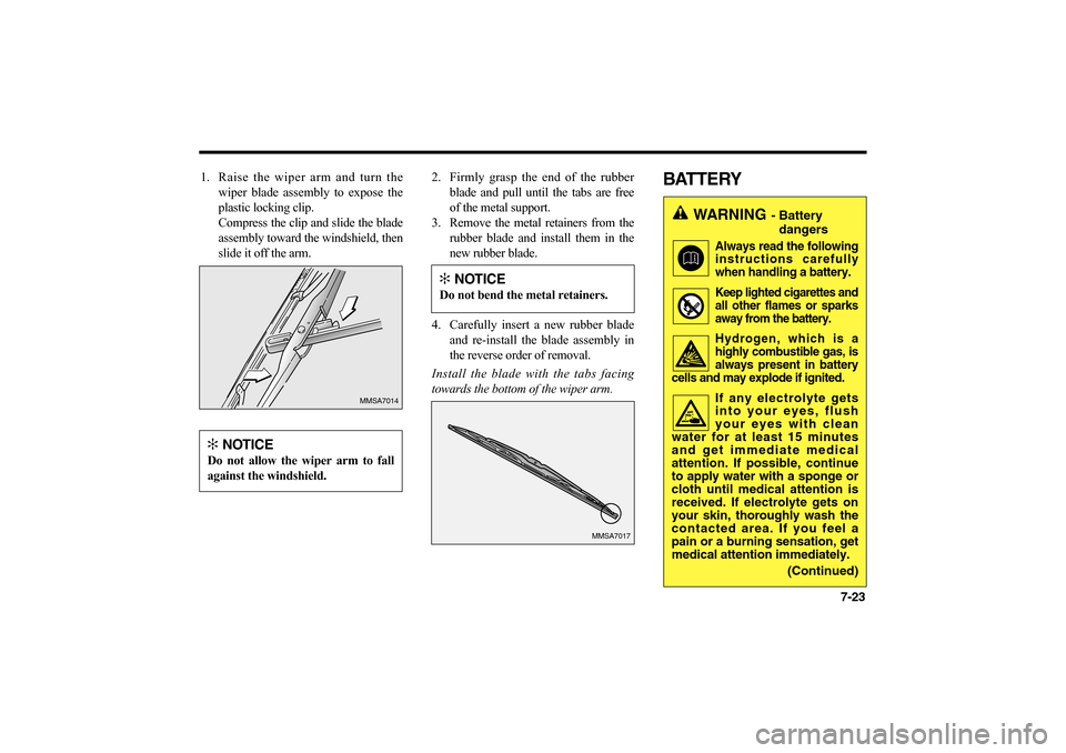
1. Raise the wiper arm and turn the
wiper blade assembly to expose the
plastic locking clip.
Compress the clip and slide the blade
assembly toward the windshield, then
slide it off the arm.2. Firmly grasp the end of the rubber
blade and pull until the tabs are free
of the metal support.
3. Remove the metal retainers from the
rubber blade and install them in the
new rubber blade.
4. Carefully insert a new rubber blade
and re-install the blade assembly in
the reverse order of removal.
Install the blade with the tabs facing
towards the bottom of the wiper arm.
BATTERY
MMSA7014
MMSA7017
✻
NOTICE
Do not allow the wiper arm to fall
against the windshield.
✻
NOTICE
Do not bend the metal retainers.
WARNING
- Battery
dangers
Always read the following
instructions carefully
when handling a battery.Keep lighted cigarettes and
all other flames or sparks
away from the battery.Hydrogen, which is a
highly combustible gas, is
always present in battery
cells and may explode if ignited.If any electrolyte gets
into your eyes, flush
your eyes with clean
water for at least 15 minutes
and get immediate medical
attention. If possible, continue
to apply water with a sponge or
cloth until medical attention is
received. If electrolyte gets on
your skin, thoroughly wash the
contacted area. If you feel a
pain or a burning sensation, get
medical attention immediately.
(Continued)
MS-CNA-Eng 7.QXD 7/25/2005 5:09 PM Page 23
Page 210 of 225
MAINTENANCE
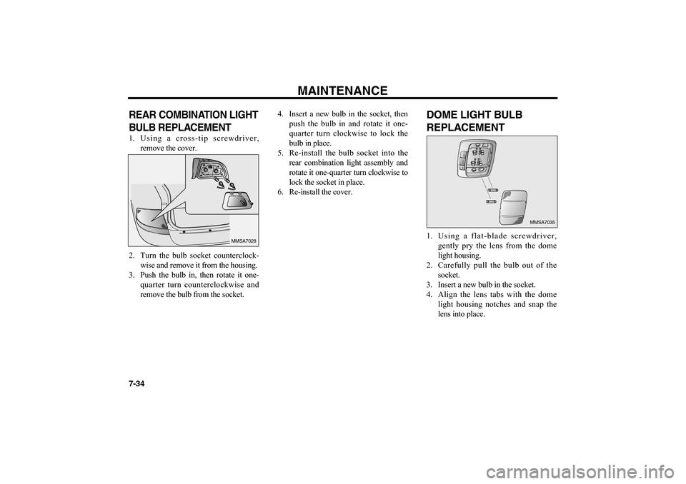
7-34REAR COMBINATION LIGHT
BULB REPLACEMENT 1. Using a cross-tip screwdriver,
remove the cover.
2. Turn the bulb socket counterclock-
wise and remove it from the housing.
3. Push the bulb in, then rotate it one-
quarter turn counterclockwise and
remove the bulb from the socket.4. Insert a new bulb in the socket, then
push the bulb in and rotate it one-
quarter turn clockwise to lock the
bulb in place.
5. Re-install the bulb socket into the
rear combination light assembly and
rotate it one-quarter turn clockwise to
lock the socket in place.
6. Re-install the cover.
DOME LIGHT BULB
REPLACEMENT1. Using a flat-blade screwdriver,
gently pry the lens from the dome
light housing.
2. Carefully pull the bulb out of the
socket.
3. Insert a new bulb in the socket.
4. Align the lens tabs with the dome
light housing notches and snap the
lens into place.
MMSA7028
O
F
FDOORON
MMSA7035
MS-CNA-Eng 7.QXD 7/25/2005 5:09 PM Page 34