Fuel lid KIA Optima 2012 3.G Owner's Manual
[x] Cancel search | Manufacturer: KIA, Model Year: 2012, Model line: Optima, Model: KIA Optima 2012 3.GPages: 382, PDF Size: 8.75 MB
Page 7 of 382
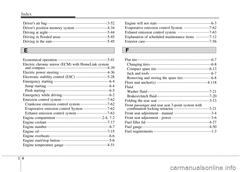
Index
4I
Driver's air bag··················\
··················\
··················\
·········3-52
Driver's position memory system ··················\
················4-34
Driving at night ··················\
··················\
··················\
········5-44
Driving in flooded areas ··················\
··················\
············5-45
Driving in the rain··················\
··················\
··················\
····5-45
Economical operation ··················\
··················\
················5-41
Electric chromic mirror (ECM) with HomeLink system and compass ··················\
··················\
··················\
··········4-39
Electric power steering ··················\
··················\
··············4-36
Electronic stability control (ESC) ··················\
···············5-28
Emergency starting ··················\
··················\
··················\
····6-4 Jump starting ··················\
··················\
··················\
···········6-4
Push starting ··················\
··················\
··················\
············6-5
Emergency while driving ··················\
··················\
·············6-2
Emission control system ··················\
··················\
············7-62 Crankcase emission control system··················\
···········7-62
Evaporative emission control System ··················\
·······7-62
Exhaust emission control system ··················\
··············7-63
Engine compartment ··················\
··················\
············2-4, 7-2
Engine coolant ··················\
··················\
··················\
·········7-17
Engine number ··················\
··················\
··················\
···········8-7
Engine oil ··················\
··················\
··················\
·················7-15\
Engine overheats ··················\
··················\
··················\
········6-6
Engine start/stop button ··················\
··················\
···············5-6
Engine temperature gauge ··················\
··················\
·········4-51 Engine will not start··················\
··················\
··················\
···6-3
Evaporative emission control System ··················\
·········7-62
Exhaust emission control system ··················\
···············7-63
Explanation of scheduled maintenance items ··············7-12
Exterior care··················\
··················\
··················\
·············7-56
Flat tire ··················\
··················\
··················\
··················\
·····6-7
Changing tires··················\
··················\
··················\
··········6-8
Compact spare tire ··················\
··················\
··················\
·6-13
Jack and tools ··················\
··················\
··················\
··········6-7
Removing and storing the spare tire···········\
··················\
·6-8
Floor mat anchor(s) ··················\
··················\
·················4-11\
8
Fluid Washer fluid··················\
··················\
··················\
···········7-21
Brakes/clutch fluid··················\
··················\
··················\
·7-20
Folding the rear seat ··················\
··················\
··················\
3-13
Front passenger and rear seat 3-point system with combination locking retractor ··················\
··················\
·3-21
Front seat adjustment - manual ··················\
··················\
···3-4
Front seat adjustment - power ··················\
··················\
·····3-6
Fuel filler lid ··················\
··················\
··················\
············4-27
Fuel gauge··················\
··················\
··················\
················4-50
Fuel requirements ··················\
··················\
··················\
······1-3
EF
Page 17 of 382
15
Introduction
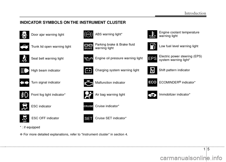
INDICATOR SYMBOLS ON THE INSTRUMENT CLUSTER
Seat belt warning light
High beam indicator
Turn signal indicator
ABS warning light*
Parking brake & Brake fluid
warning light
Engine oil pressure warning light
Charging system warning light
ESC indicator
ESC OFF indicator
Malfunction indicator
Air bag warning light
Cruise indicator*
Cruise SET indicator*
Low fuel level warning light
❈ For more detailed explanations, refer to “Instrument cluster” in section 4.
Door ajar warning light
Trunk lid open warning light
Front fog light indicator*
Engine coolant temperature
warning light
Electric power steering (EPS)
system warning light*
Shift pattern indicator
* : if equipped ECOMINDER
®indicator*ECO
Immobilizer indicator*
Page 19 of 382
Your vehicle at a glance
22
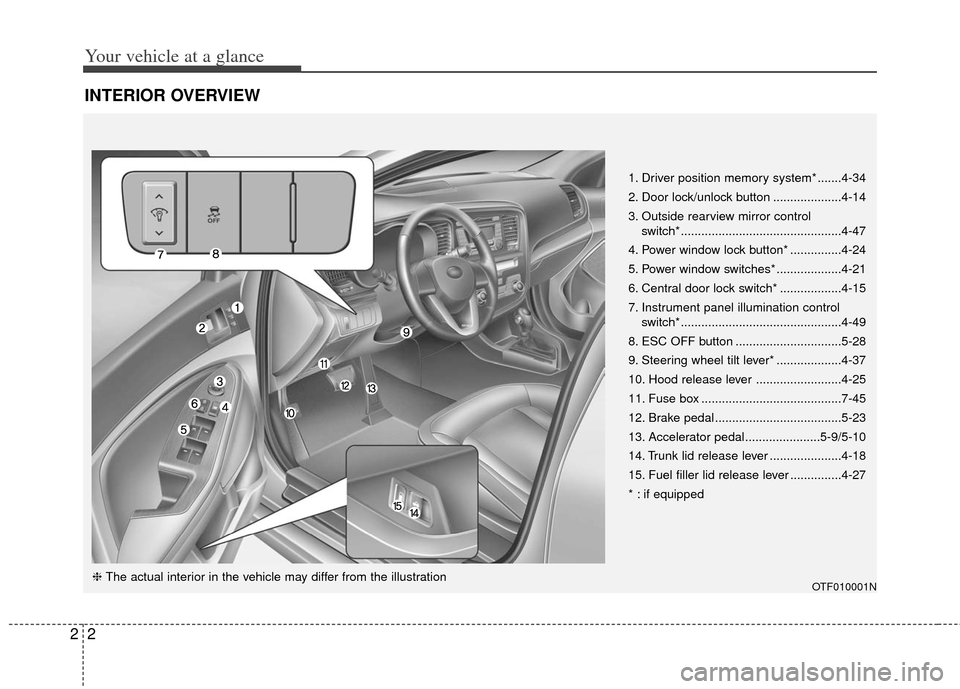
INTERIOR OVERVIEW
1. Driver position memory system* .......4-34
2. Door lock/unlock button ....................4-14
3. Outside rearview mirror control switch* ...............................................4-47
4. Power window lock button* ...............4-24
5. Power window switches* ...................4-21
6. Central door lock switch* ..................4-15
7. Instrument panel illumination control switch* ...............................................4-49
8. ESC OFF button ...............................5-28
9. Steering wheel tilt lever* ...................4-37
10. Hood release lever .........................4-25
11. Fuse box .........................................7-45
12. Brake pedal .....................................5-23
13. Accelerator pedal......................5-9/5-10
14. Trunk lid release lever .....................4-18
15. Fuel filler lid release lever ...............4-27
* : if equipped
OTF010001N❈ The actual interior in the vehicle may differ from the illustration
Page 88 of 382
4
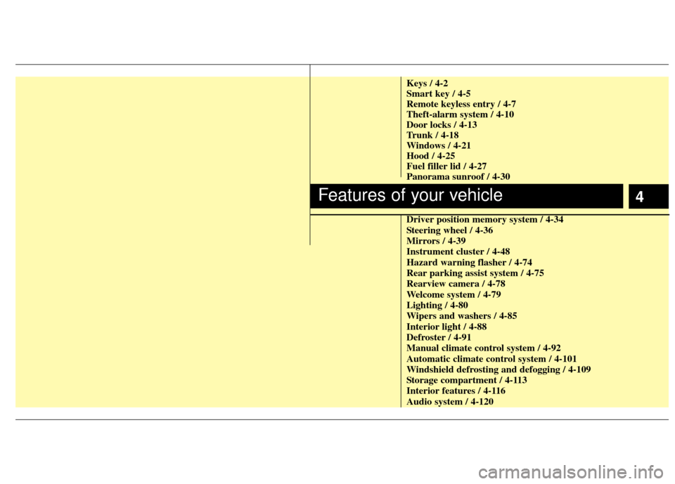
Keys / 4-2
Smart key / 4-5
Remote keyless entry / 4-7
Theft-alarm system / 4-10
Door locks / 4-13
Trunk / 4-18
Windows / 4-21
Hood / 4-25
Fuel filler lid / 4-27
Panorama sunroof / 4-30
Driver position memory system / 4-34
Steering wheel / 4-36
Mirrors / 4-39
Instrument cluster / 4-48
Hazard warning flasher / 4-74
Rear parking assist system / 4-75
Rearview camera / 4-78
Welcome system / 4-79
Lighting / 4-80
Wipers and washers / 4-85
Interior light / 4-88
Defroster / 4-91
Manual climate control system / 4-92
Automatic climate control system / 4-101
Windshield defrosting and defogging / 4-109
Storage compartment / 4-113
Interior features / 4-116
Audio system / 4-120
Features of your vehicle
Page 114 of 382
427
Features of your vehicle
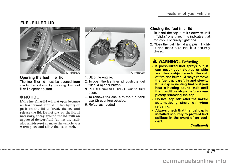
Opening the fuel filler lid
The fuel filler lid must be opened from
inside the vehicle by pushing the fuel
filler lid opener button.
✽ ✽NOTICE
If the fuel filler lid will not open because
ice has formed around it, tap lightly or
push on the lid to break the ice and
release the lid. Do not pry on the lid. If
necessary, spray around the lid with an
approved de-icer fluid (do not use radi-
ator anti-freeze) or move the vehicle to a
warm place and allow the ice to melt.
1. Stop the engine.
2. To open the fuel filler lid, push the fuel
filler lid opener button.
3. Pull the fuel filler lid (1) out to fully open.
4. To remove the cap, turn the fuel tank cap (2) counterclockwise.
5. Refuel as needed.
Closing the fuel filler lid
1. To install the cap, turn it clockwise until it “clicks” one time. This indicates that
the cap is securely tightened.
2. Close the fuel filler lid and push it light- ly and make sure that it is securely
closed.
FUEL FILLER LID
OTF040026OTF040027
WARNING - Refueling
If pressurized fuel sprays out, itcan cover your clothes or skin
and thus subject you to the risk
of fire and burns. Always remove
the fuel cap carefully and slowly.
If the cap is venting fuel or if you
hear a hissing sound, wait until
the condition stops before com-
pletely removing the cap.
Do not "top off" after the nozzle automatically shuts off when
refueling.
Always check that the fuel cap is installed securely to prevent fuel
spillage in the event of an acci-
dent.
(Continued)
Page 115 of 382
Features of your vehicle
28
4
(Continued)
Do not get back into a vehicle
once you have begun refueling
since you can generate static
electricity by touching, rubbing
or sliding against any item or fab-
ric (polyester, satin, nylon, etc.)
capable of producing static elec-
tricity. Static electricity discharge
can ignite fuel vapors resulting in
rapid burning. If you must re-
enter the vehicle, you should
once again eliminate potentially
dangerous static electricity dis-
charge by touching a metal part
of the vehicle, away from the fuel
filler neck, nozzle or other gaso-
line source.
When using an approved portable fuel container, be sure to
place the container on the
ground prior to refueling. Static
electricity discharge from the
container can ignite fuel vapors
causing a fire. Once refueling has
begun, contact with the vehicle
should be maintained until the
filling is complete.
(Continued)WARNING - Refueling dan-
gers
Automotive fuels are flammable
materials. When refueling, please
note the following guidelines care-
fully. Failure to follow these guide-
lines may result in severe personal
injury, severe burns or death by fire
or explosion.
Read and follow all warnings atthe gas station facility.
Before refueling note the location of the Emergency Gasoline Shut-
Off, if available, at the gas station
facility.
Before touching the fuel nozzle, you should eliminate potentially
dangerous static electricity dis-
charge by touching another metal
part of the vehicle, a safe dis-
tance away from the fuel filler
neck, nozzle, or other gas source.
(Continued)
(Continued)
Gasoline vapors are dangerous.Before refueling, always stop the
engine and never smoke or allow
sparks and open flames near the
filler area.
Never operate your vehicle with- out a filler cap properly installed,
flammable vapors and gasoline
could leak out in dangerous situ-
ations such as a collision or
rollover. If the filler cap must be
replaced, only use genuine Kia
replacement parts.
Tighten the cap until it clicks one time, otherwise the " "light will
illuminate.
Page 362 of 382
751
Maintenance
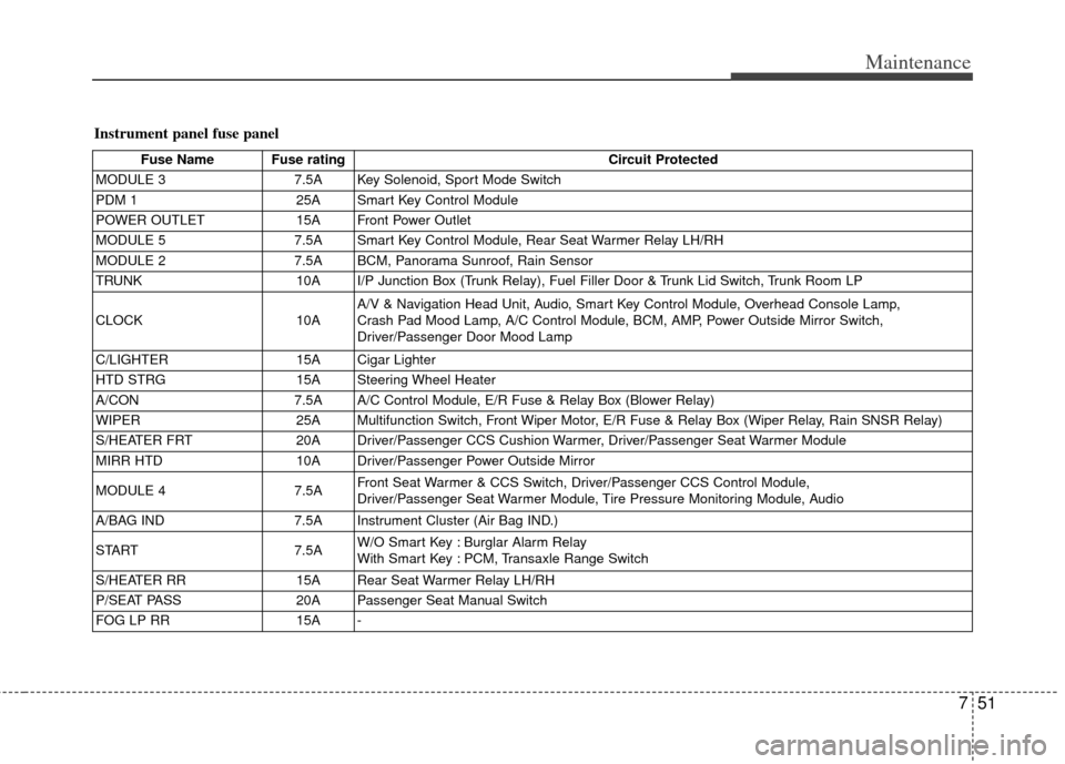
Instrument panel fuse panel
Fuse Name Fuse ratingCircuit Protected
MODULE 3 7.5A Key Solenoid, Sport Mode Switch
PDM 1 25A Smart Key Control Module
POWER OUTLET 15A Front Power Outlet
MODULE 5 7.5A Smart Key Control Module, Rear Seat Warmer Relay LH/RH
MODULE 2 7.5A BCM, Panorama Sunroof, Rain Sensor
TRUNK 10A I/P Junction Box (Trunk Relay), Fuel Filler Door & Trunk Lid Switch, Trunk Room LP
CLOCK 10AA/V & Navigation Head Unit, Audio, Smart Key Control Module, Overhead Console Lamp,
Crash Pad Mood Lamp, A/C Control Module, BCM, AMP, Power Outside Mirror Switch,
Driver/Passenger Door Mood Lamp
C/LIGHTER 15A Cigar Lighter
HTD STRG 15A Steering Wheel Heater
A/CON 7.5A A/C Control Module, E/R Fuse & Relay Box (Blower Relay)
WIPER 25A Multifunction Switch, Front Wiper Motor, E/R Fuse & Relay Box (Wiper Relay, Rain SNSR Relay)
S/HEATER FRT 20A Driver/Passenger CCS Cushion Warmer, Driver/Passenger Seat Warmer Module
MIRR HTD 10A Driver/Passenger Power Outside Mirror
MODULE 4 7.5AFront Seat Warmer & CCS Switch, Driver/Passenger CCS Control Module,
Driver/Passenger Seat Warmer Module, Tire Pressure Monitoring Module, Audio
A/BAG IND 7.5A Instrument Cluster (Air Bag IND.)
START 7.5AW/O Smart Key : Burglar Alarm Relay
With Smart Key : PCM, Transaxle Range Switch
S/HEATER RR 15A Rear Seat Warmer Relay LH/RH
P/SEAT PASS 20A Passenger Seat Manual Switch
FOG LP RR 15A -