Wire KIA OPTIMA 2019 Owners Manual
[x] Cancel search | Manufacturer: KIA, Model Year: 2019, Model line: OPTIMA, Model: KIA OPTIMA 2019Pages: 577, PDF Size: 13.79 MB
Page 24 of 577
Safety features of your vehicle
63
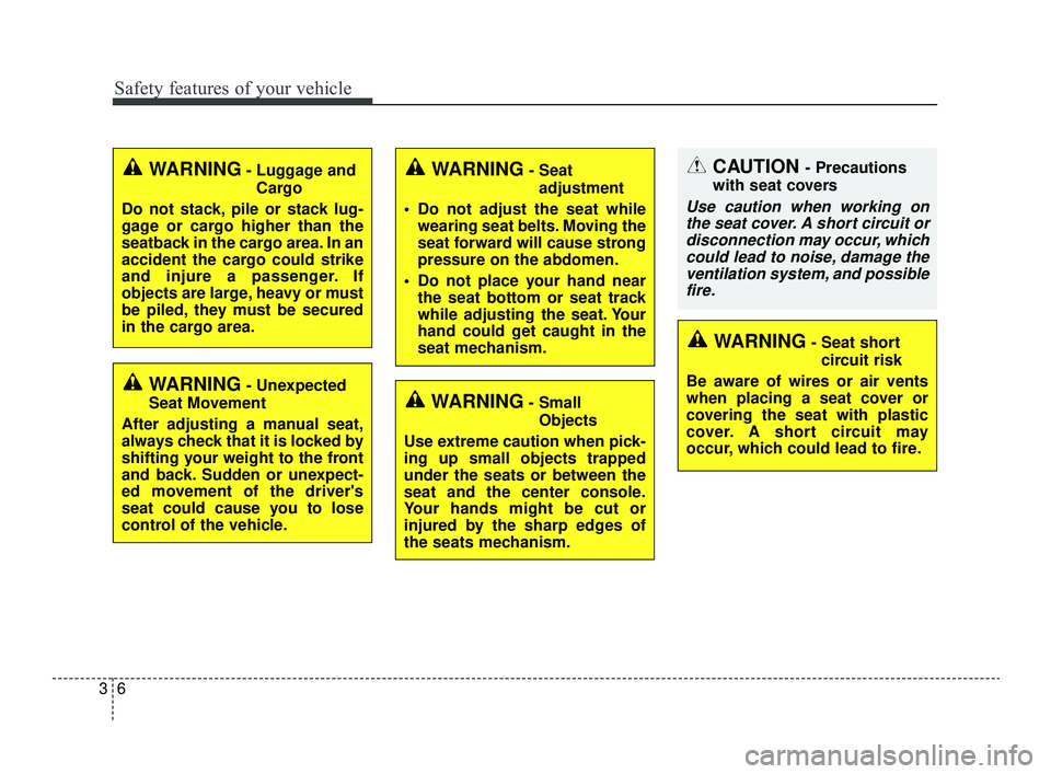
WARNING- Unexpected
Seat Movement
After adjusting a manual seat,
always check that it is locked by
shifting your weight to the front
and back. Sudden or unexpect-
ed movement of the driver's
seat could cause you to lose
control of the vehicle.
WARNING- Luggage and Cargo
Do not stack, pile or stack lug-
gage or cargo higher than the
seatback in the cargo area. In an
accident the cargo could strike
and injure a passenger. If
objects are large, heavy or must
be piled, they must be secured
in the cargo area.WARNING- Seat adjustment
Do not adjust the seat while wearing seat belts. Moving the
seat forward will cause strong
pressure on the abdomen.
Do not place your hand near the seat bottom or seat track
while adjusting the seat. Your
hand could get caught in the
seat mechanism.
WARNING- Small
Objects
Use extreme caution when pick-
ing up small objects trapped
under the seats or between the
seat and the center console.
Your hands might be cut or
injured by the sharp edges of
the seats mechanism.
CAUTION - Precautions
with seat covers
Use caution when working on the seat cover. A short circuit ordisconnection may occur, whichcould lead to noise, damage theventilation system, and possiblefire.
WARNING- Seat short
circuit risk
Be aware of wires or air vents
when placing a seat cover or
covering the seat with plastic
cover. A short circuit may
occur, which could lead to fire.
JFa PE USA 3.QXP 5/18/2018 7:13 PM Page 6
Page 189 of 577
499
Features of your vehicle
When more than two objects aresensed at the same time, the clos-
est one will be recognized first.
Types of warning sound
When an object is 47 in. to 24 in.(120 cm to 61 cm) from the rear
bumper: Buzzer beeps intermit-
tently.
When an object is 24 in. to 12 in. (60 cm to 31 cm) from the rear
bumper: Buzzer beeps more fre-
quently.
When an object is within 16 in. (40 cm) of the rear bumper:
Buzzer sounds continuously.
Non-operational conditions of
parking distance warning-
reverse
The parking distance warning-
reverse may not operate properly
when:
1. Moisture is frozen to the sensor. (It will operate normally once the
moisture clears.)
2. The sensor is covered with foreign matter, such as snow or water, or
the sensor cover is blocked. (It will
operate normally when the materi-
al is removed or the sensor is no
longer blocked.)
3. Driving on uneven road surfaces (unpaved roads, gravel, bumps,
gradient).
4. Objects generating excessive noise (vehicle horns, loud motor-
cycle engines, or truck air brakes)
are within range of the sensor.
5. Rain or water spray exists.
6. Wireless transmitters or mobile phones are within range of the
sensor.
7. The sensor is covered with snow.
8. Trailer towing The detecting range may decrease
when:
1. The sensor is covered with foreign
matter such as snow or water.
(The sensing range will return to
normal when removed.)
2. Outside air temperature is extremely hot or cold.
The following objects may not be
recognized by the sensor:
1. Sharp or slim objects such as ropes, chains or small poles.
2. Objects which tend to absorb the sensor frequency such as clothes,
sound absorbent material or snow.
3. Undetectable objects smaller than 40 in. (1 m) in height and narrower
than 6 in. (14 cm) in diameter.
JFa PE USA 4.qxp 5/18/2018 7:22 PM Page 99
Page 398 of 577
Driving your vehicle
146
5
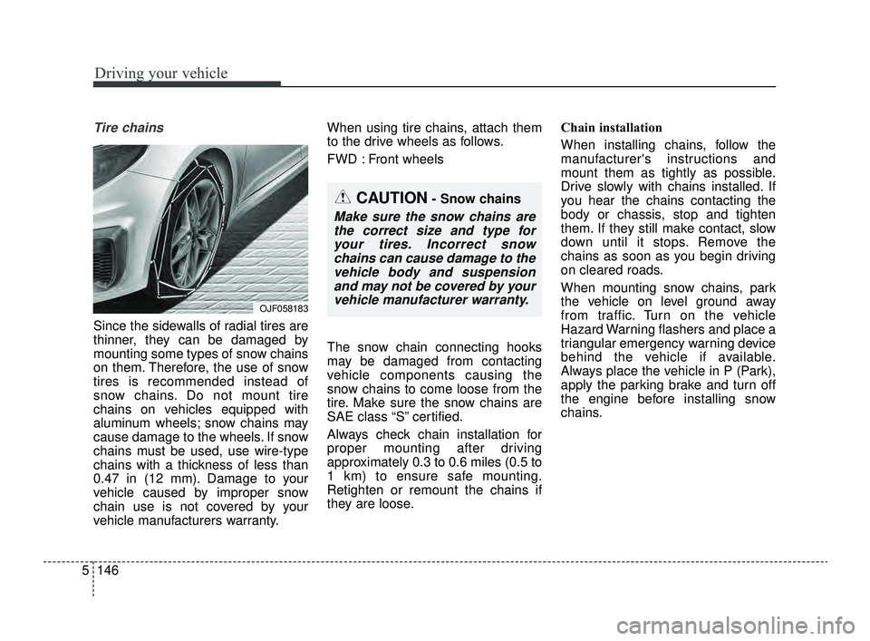
Tire chains
Since the sidewalls of radial tires are
thinner, they can be damaged by
mounting some types of snow chains
on them. Therefore, the use of snow
tires is recommended instead of
snow chains. Do not mount tire
chains on vehicles equipped with
aluminum wheels; snow chains may
cause damage to the wheels. If snow
chains must be used, use wire-type
chains with a thickness of less than
0.47 in (12 mm). Damage to your
vehicle caused by improper snow
chain use is not covered by your
vehicle manufacturers warranty. When using tire chains, attach them
to the drive wheels as follows.
FWD : Front wheels
The snow chain connecting hooks
may be damaged from contacting
vehicle components causing the
snow chains to come loose from the
tire. Make sure the snow chains are
SAE class “S” certified.
Always check chain installation for
proper mounting after driving
approximately 0.3 to 0.6 miles (0.5 to
1 km) to ensure safe mounting.
Retighten or remount the chains if
they are loose.
Chain installation
When installing chains, follow the
manufacturer's instructions and
mount them as tightly as possible.
Drive slowly with chains installed. If
you hear the chains contacting the
body or chassis, stop and tighten
them. If they still make contact, slow
down until it stops. Remove the
chains as soon as you begin driving
on cleared roads.
When mounting snow chains, park
the vehicle on level ground away
from traffic. Turn on the vehicle
Hazard Warning flashers and place a
triangular emergency warning device
behind the vehicle if available.
Always place the vehicle in P (Park),
apply the parking brake and turn off
the engine before installing snow
chains.
CAUTION- Snow chains
Make sure the snow chains are
the correct size and type foryour tires. Incorrect snowchains can cause damage to thevehicle body and suspensionand may not be covered by yourvehicle manufacturer warranty.
OJF058183
JFa PE USA 5.QXP 5/17/2018 6:16 PM Page 146
Page 494 of 577

Maintenance
54
7
Temperature -A, B & C
The temperature grades are A (the
highest), B and C representing the
tire’s resistance to the generation of
heat and its ability to dissipate heat
when tested under controlled condi-
tions on a specified indoor laboratory
test wheel.
Sustained high temperature can
cause the material of the tire to
degenerate and reduce tire life, and
excessive temperature can lead to
sudden tire failure. The grade C cor-
responds to a level of performance
which all passenger car tires must
meet under the Federal Motor
Vehicle Safety Standard No. 109.
Grades B and A represent higher
levels of performance on the labora-
tory test wheel than the minimum
required by law. Tire terminology and definitions
Air Pressure:
The amount of air
inside the tire pressing outward on
the tire. Air pressure is expressed in
kilopascal (kPa) or pounds per
square inch (psi).
Accessory Weight: This means the
combined weight of optional acces-
sories. Some examples of optional
accessories are, automatic transmis-
sion, power seats, and air condition-
ing.
Aspect Ratio: The relationship of a
tire's height to its width.
Belt: A rubber coated layer of cords
that is located between the plies and
the tread. Cords may be made from
steel or other reinforcing materials.
Bead: The tire bead contains steel
wires wrapped by steel cords that
hold the tire onto the rim.
Bias Ply Tire: A pneumatic tire in
which the plies are laid at alternate
angles less than 90 degrees to the
centerline of the tread. Cold Tire Pressure:
The amount of
air pressure in a tire, measured in
kilopascals (kPa) or pounds per
square inch (psi) before a tire has
built up heat from driving.
Curb Weight: This means the weight
of a motor vehicle with standard and
optional equipment including the
maximum capacity of fuel, oil and
coolant, but without passengers and
cargo.
DOT Markings: A code molded into
the sidewall of a tire signifying that
the tire is in compliance with the U.S.
Department of Transportation motor
vehicle safety standards. The DOT
code includes the Tire Identification
Number (TIN), an alphanumeric des-
ignator which can also identify the
tire manufacturer, production plant,
brand and date of production.
JFa PE USA 7.qxp 5/17/2018 6:35 PM Page 54
Page 498 of 577

Maintenance
58
7
Tire chains
Tire chains, if necessary, should be
installed on the front wheels.
Be sure that the chains are installed
in accordance with the manufactur-
er's instructions.
To minimize tire and chain wear, do
not continue to use tire chains when
they are no longer needed.
When driving on roads covered
with snow or ice, drive at less than
20 mph (30 km/h).
Use the SAE “S” class or wire chains.
If you hear noise caused by chains contacting the body, retighten the
chain to avoid contact with the
vehicle body.
To prevent body damage, retighten the chains after driving 0.3~0.6
miles (0.5~1.0 km).
Do not use tire chains on vehicles equipped with aluminum wheels.
In unavoidable circumstances, use
a wire type chain.
Use wire chains less than 0.47 inches (12 mm) to prevent damage
to the chain’s connection.
Radial-ply tires
Radial-ply tires provide improved
tread life, road hazard resistance and
smoother high speed ride. The radi-
al-ply tires used on this vehicle are
of belted construction and are select-
ed to complement the ride and han-
dling characteristics of your vehicle.
Radial-ply tires have the same load
carrying capacity as bias-ply or bias
belted tires of the same size and use
the same recommended inflation
pressure. Mixing of radial-ply tires
with bias-ply or bias belted tires is
not recommended. Any combina-
tions of radial-ply and bias-ply or bias
belted tires when used on the same
vehicle will seriously deteriorate
vehicle handling. The best rule to fol-
low is: identical radial-ply tires should
always be used as a set of four. Longer wearing tires can be more
susceptible to irregular tread wear. It
is very important to follow the tire
rotation interval shown in this section
to achieve the tread life potential of
these tires. Cuts and punctures in
radial-ply tires are repairable only in
the tread area, because of sidewall
flexing. Consult your tire dealer for
radial-ply tire repairs.
JFa PE USA 7.qxp 5/17/2018 6:35 PM Page 58
Page 500 of 577
Maintenance
60
7
FUSES
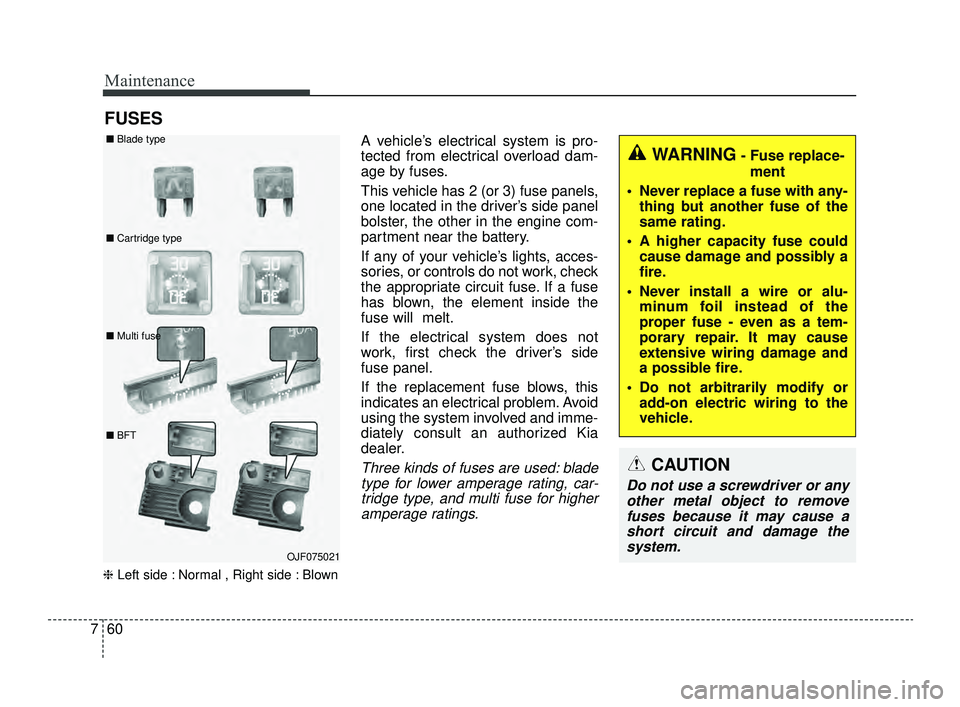
❈ Left side : Normal , Right side : Blown
A vehicle’s electrical system is pro-
tected from electrical overload dam-
age by fuses.
This vehicle has 2 (or 3) fuse panels,
one located in the driver’s side panel
bolster, the other in the engine com-
partment near the battery.
If any of your vehicle’s lights, acces-
sories, or controls do not work, check
the appropriate circuit fuse. If a fuse
has blown, the element inside the
fuse will melt.
If the electrical system does not
work, first check the driver’s side
fuse panel.
If the replacement fuse blows, this
indicates an electrical problem. Avoid
using the system involved and imme-
diately consult an authorized Kia
dealer.
Three kinds of fuses are used: blade
type for lower amperage rating, car-tridge type, and multi fuse for higheramperage ratings.
WARNING- Fuse replace-
ment
Never replace a fuse with any- thing but another fuse of the
same rating.
A higher capacity fuse could cause damage and possibly a
fire.
Never install a wire or alu- minum foil instead of the
proper fuse - even as a tem-
porary repair. It may cause
extensive wiring damage and
a possible fire.
Do not arbitrarily modify or add-on electric wiring to the
vehicle.
CAUTION
Do not use a screwdriver or anyother metal object to removefuses because it may cause ashort circuit and damage thesystem.
OJF075021
■
Blade type
■ Cartridge type
■ Multi fuse
■ BFT
JFa PE USA 7.qxp 5/17/2018 6:35 PM Page 60
Page 501 of 577
761
Maintenance
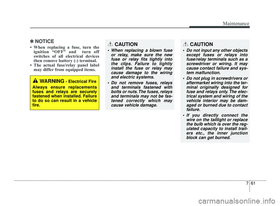
✽ ✽NOTICE
• When replacing a fuse, turn the
ignition “OFF” and turn off
switches of all electrical devices
then remove battery (-) terminal.
• The actual fuse/relay panel label may differ from equipped items.
WARNING- Electrical Fire
Always ensure replacements
fuses and relays are securely
fastened when installed. Failure
to do so can result in a vehicle
fire.
CAUTION
When replacing a blown fuse or relay, make sure the newfuse or relay fits tightly intothe clips. Failure to tightlyinstall the fuse or relay maycause damage to the wiringand electric systems.
Do not remove fuses, relays and terminals fastened withbolts or nuts. The fuses, relaysand terminals may not be fas-tened correctly which maycause vehicle damage.
CAUTION
Do not input any other objects except fuses or relays intofuse/relay terminals such as ascrewdriver or wiring. It maycause contact failure and sys-tem malfunction.
Do not plug in screwdrivers or aftermarket wiring into the ter-minal originally designed forfuse and relays only. The elec-trical system and wiring of thevehicle interior may be dam-aged or burned due to contactfailure.
If you directly connect the wire on the taillight or replacethe bulb which is over the reg-ulated capacity to install trail-ers etc., the inner junctionblock can get burned.
JFa PE USA 7.qxp 5/17/2018 6:35 PM Page 61
Page 502 of 577
Maintenance
62
7
✽ ✽
NOTICE- Remodeling
Prohibited
Do not rewire your vehicle in any
way as doing so may affect the per-
formance of several safety features
in your vehicle. Rewiring your vehi-
cle may also void your warranty and
cause you to be responsible for any
subsequent vehicle damage which
may result.
✽ ✽ NOTICE- Window tinting pre-
caution
Window tint (especially metallic
film) might cause communication
errors or poor radio reception, and
malfunctioning automatic lighting
system due to reflections from the
mirror tint inside the vehicle. The
solution used might also leak into
the electronic components, causing
malfunctions or damage.
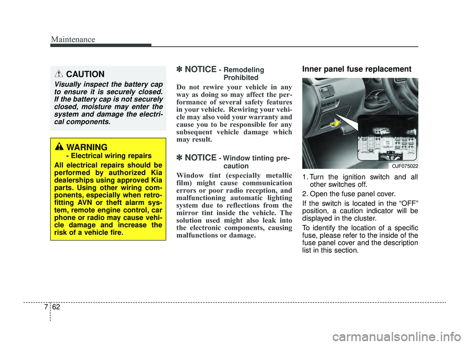
Inner panel fuse replacement
1. Turn the ignition switch and all other switches off.
2. Open the fuse panel cover.
If the switch is located in the “OFF”
position, a caution indicator will be
displayed in the cluster.
To identify the location of a specific
fuse, please refer to the inside of the
fuse panel cover and the description
list in this section.
CAUTION
Visually inspect the battery cap to ensure it is securely closed.If the battery cap is not securelyclosed, moisture may enter thesystem and damage the electri-cal components.
WARNING
- Electrical wiring repairs
All electrical repairs should be
performed by authorized Kia
dealerships using approved Kia
parts. Using other wiring com-
ponents, especially when retro-
fitting AVN or theft alarm sys-
tem, remote engine control, car
phone or radio may cause vehi-
cle damage and increase the
risk of a vehicle fire.
OJF075022
JFa PE USA 7.qxp 5/17/2018 6:35 PM Page 62
Page 508 of 577

Maintenance
68
7
Fuse NameFuse ratingCircuit Protected
WASHER15AMultifunction Switch (Wiper Low & Washer Switch)
MODULE 810AA/C Control Module, Driver/Passenger Door Module
CLUSTER10AInstrument Cluster (IG1)
MULTI MEDIA15AAudio, A/V & Navigation Head Unit, Keyboard
HEATED
STEERING15ABCM (Steering Wheel Heated)
MODULE 110AConsole Switch, Key Solenoid, Driver/Passenger Door Module, BCM
DR LOCK20ADoor Lock Relay, Door Unlock Relay
SMART KEY15ASmart Key Control Module
A/BAG IND10AInstrument Cluster (Air Bag IND. Power)
TRUNK10ATrunk Lid Relay, Fuel Filler & Trunk Open Switch, Trunk Lid Motor, ICM Relay Box (Fuel Filler Open Relay)
SUNROOF 220ASunroof Control Unit (Roller)
MEMORY 110AInstrument Cluster, A/C Control Module, Data Link Connector, Wireless Charger, Driver IMS Module, Rain
Sensor, ICM Relay Box (Outside Mirror Folding/Unfolding Mirror Relay), Security Indicator, Auto Light &
Photo Sensor, Driver/Passenger Door Module, Electro Chromic Mirror
S/HEATER RR25ARear Seat Warmer Control Module
SUNROOF 120ASunroof Control Unit (Glass)
JFa PE USA 7.qxp 5/17/2018 6:35 PM Page 68
Page 509 of 577
769
Maintenance
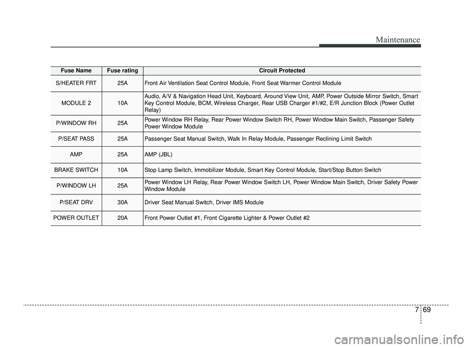
Fuse NameFuse ratingCircuit Protected
S/HEATER FRT25AFront Air Ventilation Seat Control Module, Front Seat Warmer Control Module
MODULE 210AAudio, A/V & Navigation Head Unit, Keyboard, Around View Unit, AMP, Power Outside Mirror Switch, Smart
Key Control Module, BCM, Wireless Charger, Rear USB Charger #1/#2, E/R Junction Block (Power Outlet
Relay)
P/WINDOW RH25APower Window RH Relay, Rear Power Window Switch RH, Power Window Main Switch, Passenger Safety
Power Window Module
P/SEAT PASS25APassenger Seat Manual Switch, Walk In Relay Module, Passenger Reclining Limit Switch
AMP25AAMP (JBL)
BRAKE SWITCH10AStop Lamp Switch, Immobilizer Module, Smart Key Control Module, Start/Stop Button Switch
P/WINDOW LH25APower Window LH Relay, Rear Power Window Switch LH, Power Window Main Switch, Driver Safety Power
Window Module
P/SEAT DRV30ADriver Seat Manual Switch, Driver IMS Module
POWER OUTLET20AFront Power Outlet #1, Front Cigarette Lighter & Power Outlet #2
JFa PE USA 7.qxp 5/17/2018 6:35 PM Page 69