KIA PICANTO 2006 Owners Manual
Manufacturer: KIA, Model Year: 2006, Model line: PICANTO, Model: KIA PICANTO 2006Pages: 281, PDF Size: 9.89 MB
Page 181 of 281
63
In case of an emergency
OVERHEATING
If your temperature gauge indicates
overheating, if you experience a loss
of power, or if you hear a loud knock-
ing or pinging noise, the engine has
probably overheated. Should any of
these symptoms occur, use the fol-
lowing procedure:
1. Turn on the hazard warning flash- er, then drive to the nearest safe
location and stop your vehicle; set
the automatic transaxle in P
(Park), or shift the manual
transaxle to N (Neutral) and apply
the parking brake.
2. Make sure the air conditioner is off.
3. If coolant or steam is boiling out of the radiator, stop the engine and
call an Authorized Kia Dealer for
assistance. If coolant is not boiling out, allowthe engine to idle and open the
hood to permit the engine to cool
gradually.
If the temperature does not go
down with the engine idling, stop
the engine and allow sufficient
time for it to cool.
4. The coolant level should then be checked. If the level in the reser-
voir is low, look for leaks at the
radiator hoses and connections,
heater hoses and connections,
radiator, and water pump. If youfind a major leak or another prob-
lem that may have caused the
engine to overheat, do not operatethe engine until it has been cor-
rected. Call an Authorized Kia
Dealer for assistance. If you do not
find a leak or other problem, care-
fully add coolant to the reservoir.
If the engine frequently overheats,
have the cooling system checkedand repaired by an Authorized Kia Dealer.
1 23456789
WARNING - Removing
radiator cap
Do not remove the radiator cap when the engine and radiator
are hot. Scalding hot coolant
and steam may blow out under
pressure. This could cause seri-
ous injury.
Page 182 of 281
In case of an emergency
4
6
EMERGENCY STARTING
Jump starting
Jump starting can be dangerous if
done incorrectly. Therefore, to avoid
harm to yourself or damage to your
vehicle or battery, follow the jump
starting procedures listed on page
6-6. If in doubt, we strongly recom-
mend that you have a competent
technician or towing service jump
start your vehicle.
✽✽ NOTICE
Use only a 12-volt jumper system.
You can damage a 12-volt starting
motor, ignition system, and other
electrical parts beyond repair by use
of a 24-volt power supply (either two
12-volt batteries in series or a 24-
volt motor generator set).
1 23456789
WARNING - Battery
• Keep all flames or sparks away from the battery. The bat-
tery produces hydrogen gas
which may explode if exposedto flame or sparks.
Do not attempt to jump start the vehicle if the discharged
battery is frozen or if the elec-
trolyte level is low; the battery
may rupture or explode.
WARNING - Battery
Never attempt to check the elec-
trolyte level of the battery as
this may cause the battery to
rupture or explode causing seri-
ous injury.
Page 183 of 281
65
In case of an emergency
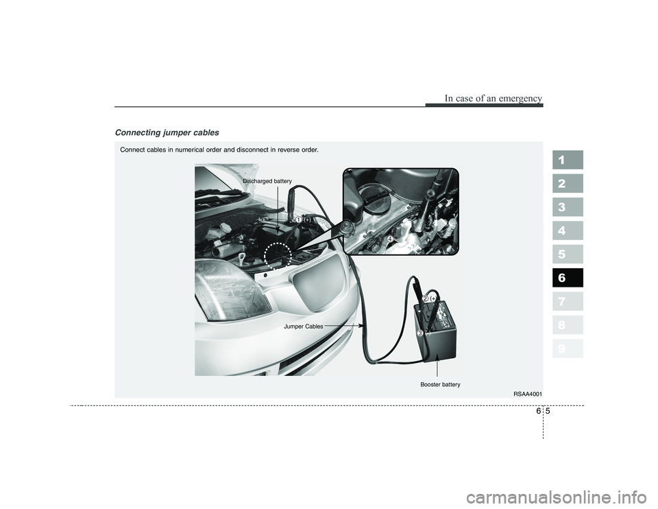
Connecting jumper cables
1 23456789
RSAA4001
Connect cables in numerical order and disconnect in reverse order.
Discharged battery
(+)
Jumper Cables
Booster battery
➀
➁
➂
➃(+)
(-)
Page 184 of 281
In case of an emergency
6
6
Jump starting procedure
1. Make sure the booster battery is
12-volt and that its negative termi-
nal is grounded.
2. If the booster battery is in another vehicle, do not allow the vehiclesto touch.
3. Turn off all unnecessary electrical loads.
4. Connect the jumper cables in the exact sequence shown in the pre-
vious illustration. First connect one
end of a jumper cable to the posi-
tive terminal of the discharged bat-
tery ( ➀), then connect the other
end to the positive terminal on the
booster battery ( ➁). Proceed to
connect one end of the other
jumper cable to the negative ter-
minal of the booster battery ( ➂),
then the other end to a solid, sta-
tionary, metallic point (for exam-
ple, the engine lifting bracket)
away from the battery ( ➃). Do not
connect it to or near any part that
moves when the engine is
cranked. Do not connect the
jumper cable from the negative
terminal of the booster battery to
the negative terminal of the dis-
charged battery. Do not allow the jumper cables to
contact anything except the cor-
rect battery terminals or the cor-
rect ground. Do not lean over the
battery when making connections.
5. Start the engine of the vehicle with the booster battery and let it run at
2,000 rpm, then start the engine of
the vehicle with the discharged
battery.
If the cause of your battery discharg-
ing is not apparent, you should haveyour vehicle checked by anAuthorized Kia Dealer.
Refer to illustration on page 6-5.
Push-starting
Your manual transaxle-equipped
vehicle should not be push-startedbecause it might damage the emis-sion control system.
Vehicles equipped with automatic
transaxle cannot be push-started.
Follow the directions in this section
for jump-starting.
1 23456789
CAUTION
Never tow a vehicle to start itbecause the sudden surge for-ward when the engine startscould cause a collision with the tow vehicle.
Page 185 of 281
67
In case of an emergency
ELECTRICAL CIRCUIT PROTECTION
Fuses
A vehicle’s electrical system is pro-
tected from electrical overload dam-
age by fuses.
This vehicle has two fuse panels,
one located in the driver's side knee
bolster, the other in the engine com-
partment near the battery. If any of your vehicle’s lights, acces-
sories, or controls do not work, check
the appropriate circuit fuse. If a fuse
has blown, the element inside thefuse will be melted.
If the electrical system does not
work, first check the driver’s sidefuse panel.
Always replace a blown fuse with
one of the same rating.
If the replacement fuse blows, this
indicates an electrical problem. Avoid
using the system involved and imme-
diately consult an Authorized Kia
Dealer.
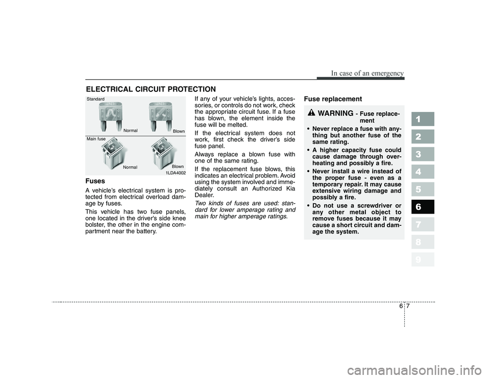
Two kinds of fuses are used: stan-
dard for lower amperage rating and main for higher amperage ratings.
Fuse replacement
1 23456789
1LDA4002
Standard Main fuse
NormalNormal
Blown
Blown
WARNING - Fuse replace-
ment
Never replace a fuse with any- thing but another fuse of the same rating.
A higher capacity fuse could cause damage through over-
heating and possibly a fire.
Never install a wire instead of the proper fuse - even as a
temporary repair. It may cause
extensive wiring damage and
possibly a fire.
Do not use a screwdriver or any other metal object to
remove fuses because it may
cause a short circuit and dam-
age the system.
Page 186 of 281
In case of an emergency
8
6
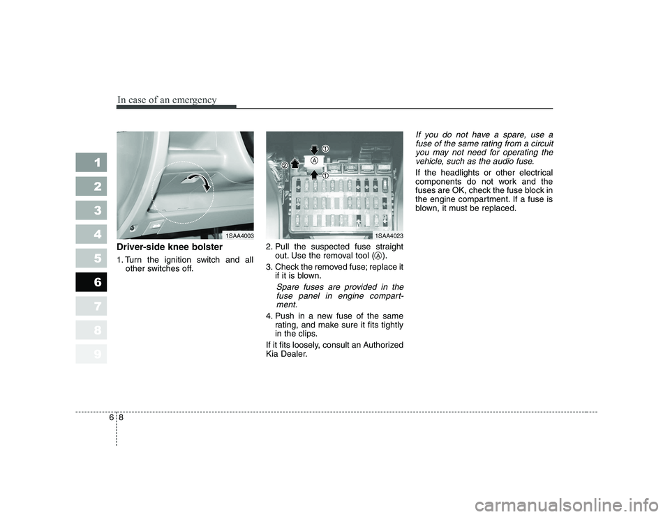
Driver-side knee bolster
1. Turn the ignition switch and all
other switches off. 2. Pull the suspected fuse straight
out. Use the removal tool ( ).
3. Check the removed fuse; replace it if it is blown.
Spare fuses are provided in the
fuse panel in engine compart-ment.
4. Push in a new fuse of the same rating, and make sure it fits tightly
in the clips.
If it fits loosely, consult an Authorized
Kia Dealer.
If you do not have a spare, use a fuse of the same rating from a circuityou may not need for operating thevehicle, such as the audio fuse.
If the headlights or other electrical
components do not work and the
fuses are OK, check the fuse block in
the engine compartment. If a fuse is
blown, it must be replaced.
1 23456789
1SAA40031SAA4023
A
A
Page 187 of 281
69
In case of an emergency
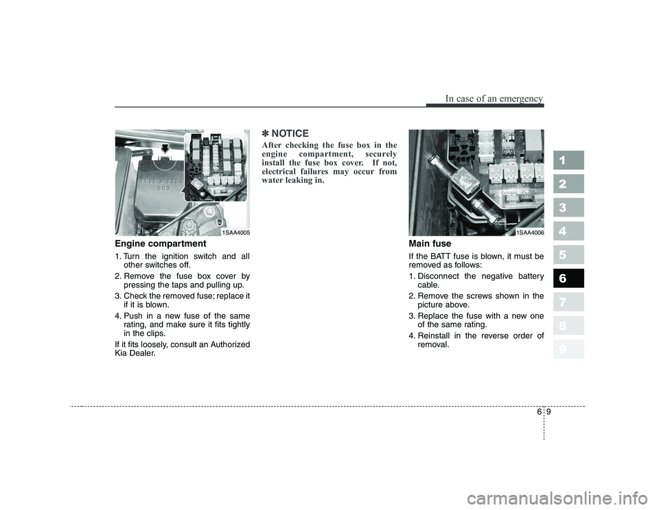
Engine compartment
1. Turn the ignition switch and allother switches off.
2. Remove the fuse box cover by pressing the taps and pulling up.
3. Check the removed fuse; replace it if it is blown.
4. Push in a new fuse of the same rating, and make sure it fits tightly
in the clips.
If it fits loosely, consult an Authorized
Kia Dealer.
✽✽ NOTICE
After checking the fuse box in the
engine compartment, securely
install the fuse box cover. If not,
electrical failures may occur from
water leaking in.
Main fuse
If the BATT fuse is blown, it must be
removed as follows:
1. Disconnect the negative battery cable.
2. Remove the screws shown in the picture above.
3. Replace the fuse with a new one of the same rating.
4. Reinstall in the reverse order of removal.
1 23456789
1SAA40051SAA4006
Page 188 of 281
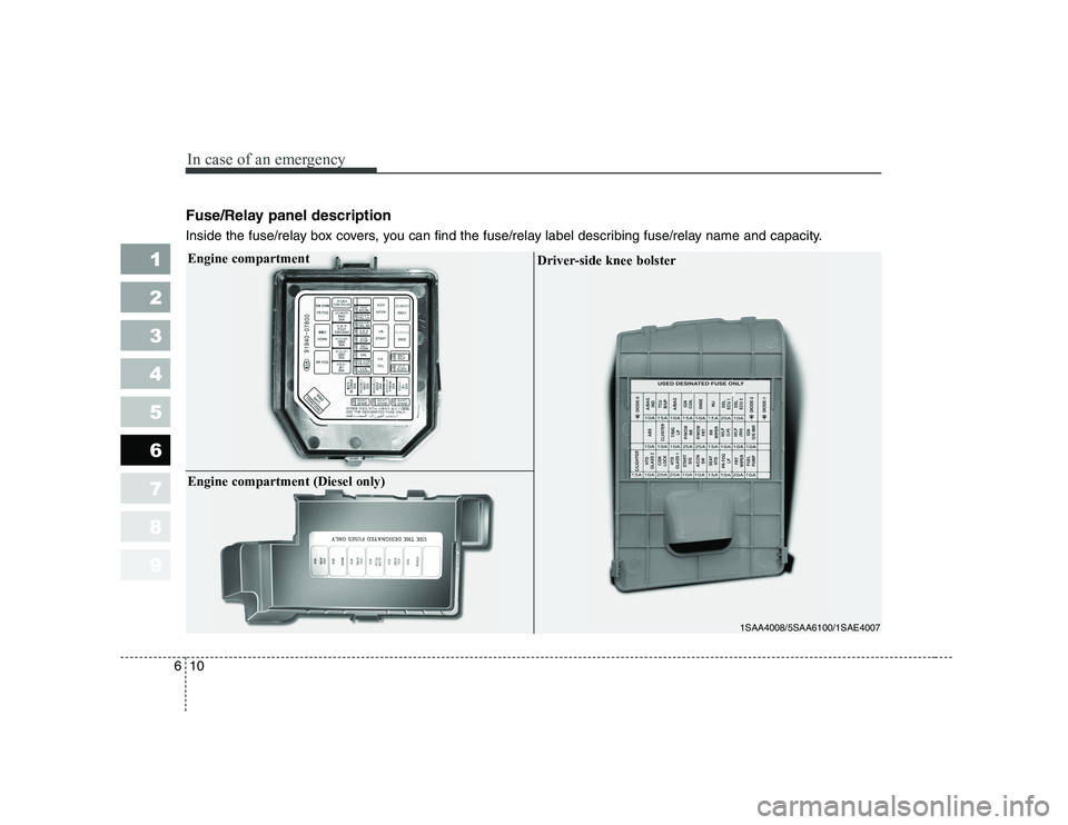
Fuse/Relay panel description
Inside the fuse/relay box covers, you can find the fuse/relay label describing fuse/relay name and capacity.
In case of an emergency
10
6
1 23456789Engine compartment
1SAA4008/5SAA6100/1SAE4007
Driver-side knee bolster
Engine compartment (Diesel only)
Page 189 of 281

611
In case of an emergency
1 23456789
Description Fuse rating Protected component
ECU1 20A (30A) Engine control unit
STOP 10A Stop light
FR/FOG 10A Front fog light
A/CON 10A Air conditioner
HORN 10A Horn
ECU2 10A Engine control unit
SPARE 10A spare fuse
SPARE 15A spare fuse
SPARE 10A spare fuse
ABS2 30A Anti-lock brake system
ABS1 30A Anti-lock brake system
B+ 30A In panel B+
BLOWER 30A Blower
IGN1 30A Ignition
IGN2 30A Ignition
TAIL LH 10A Tail light (left)
TAIL RH 10A Tail light (right)
DRL 10A Daytime running light
HAZARD 15A Hazard warning flasher
R/LP 10A Room lamp
AUDIO 15A Audio
P/WDW 30A Power windowDescription Fuse rating Protected component
RAD 30A Radiator fan
BATT 100A (120A) Alternator, Battery
F/FOG - Front fog light relay
A/CON - Air conditioner relay
HORN - Horn relay
START - Start motor relay
RAD1 - Radiator fan relay
RAD2 - Radiator fan relay
RR FOG - Rear fog light relay
TAIL - Tail light relay
Engine compartment
Engine compartment (Diesel only)
Description Fuse rating Protected component
FFHTS 30A
Fuel filter heater temporary sensor
GLOW PLUG 80A Glow plug
MDPS 80A Motor driven power steering
PTC HTR1 40A PTC heater1
PTC HTR2 40A PTC heater2
PTC HTR3 40A PTC heater3
Page 190 of 281
In case of an emergency
12
6
1 23456789
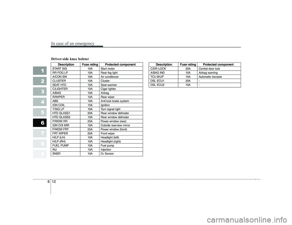
Driver-side knee bolster
Description Fuse rating Protected component
START SIG 10A Start motor
RR FOG LP 10A Rear fog light
A/CON SW 10A Air conditioner
CLUSTER 10A Cluster
SEAT HTD 15A Seat warmer
C/LIGHTER 15A Cigar lighter
A/BAG 10A Airbag
R/WIPER 15A Rear wiper
ABS 10A Anti-lock brake system
IGN COIL 15A Ignition
T/SIG LP 10A Turn signal light
HTD GLASS1 20A Rear window defroster
HTD GLASS2 10A Rear window defroster
P/WDW RR 25A Power window (rear)
IGN O/S MIR 10A Outside rearview mirror
P/WDW FRT 25A Power window (front)
FRT WIPER 20A Front wiper
H/LP (LH) 10A Headlight (left)
H/LP (RH) 10A Headlight (right)
FUEL PUMP 10A Fuel pump
INJ 15A Injection
SNSR 10A O 2SensorDescription Fuse rating Protected component
C/DR LOCK 20A Central door lock
A/BAG IND 10A Airbag warning
TCU B/UP 15A Automatic tranaxle
DSL ECU1 20A -
DSL ECU2 10A -