Motor KIA PICANTO 2012 User Guide
[x] Cancel search | Manufacturer: KIA, Model Year: 2012, Model line: PICANTO, Model: KIA PICANTO 2012Pages: 840, PDF Size: 41.16 MB
Page 140 of 840
467
Features of your vehicle
Non-operational conditions of rear parking assist system
The rear parking assist system may
not operate properly when:
1. Moisture is frozen to the sensor. (It willoperate normally when the moisture has been cleared.)
2. The sensor is covered with foreign matter, such as snow or water, or the
sensor cover is blocked. (It will operate
normally when the material is removed
or the sensor is no longer blocked.)
3. Driving on uneven road surfaces (unpaved roads, gravel, bumps, gradi-ent).
4. Objects generating excessive noise (vehicle horns, loud motorcycle
engines, or truck air brakes) are within
range of the sensor.
5. Heavy rain or water spray exists.
6. Wireless transmitters or mobile phones are within range of the sensor.
7. The sensor is covered with snow.
8. Trailer towing The detecting range may decrease when:
1. The sensor is stained with foreign mat-
ter such as snow or water. (The sens-
ing range will return to normal when
removed.)
2. Outside air temperature is extremely hot or cold.
The following objects may not be rec-
ognized by the sensor:
1. Sharp or slim objects such as ropes, chains or small poles.
2. Objects which tend to absorb the sen- sor frequency such as clothes, spongy
material or snow.
3. Undetectable objects smaller than 1 m (40 in.) in height and narrower than 14
cm (6 in.) in diameter. Rear parking assist system pre- cautions
The rear parking assist system may
not sound sequentially depending on the speed and shapes of the objectsdetected.
The rear parking assist system may malfunction if the vehicle bumperheight or sensor installation has been
modified or damaged. Any non-factory
installed equipment or accessories
may also interfere with the sensor per-
formance.
The sensor may not recognize objects less than 40 cm (15 in.) from the sen-
sor, or it may sense an incorrect dis-
tance. Use caution.
When the sensor is frozen or stained with snow, dirt, or water, the sensor
may be inoperative until the stains are
removed using a soft cloth.
Do not push, scratch or strike the sen- sor. Sensor damage could occur.
Page 294 of 840
Driving your vehicle
50
5
Driving in flooded areas
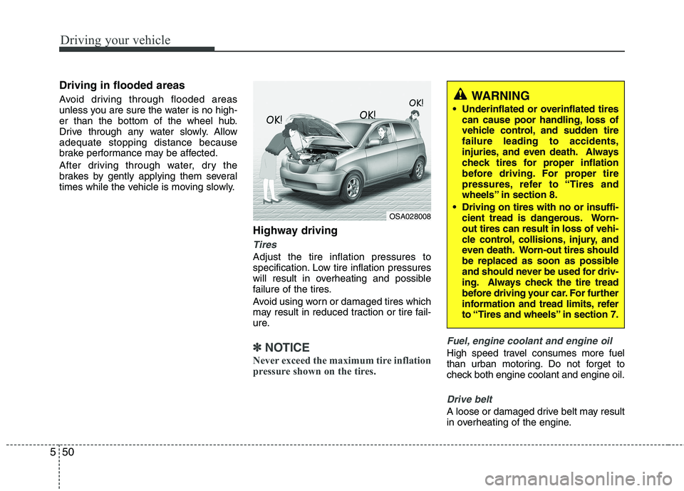
Avoid driving through flooded areas
unless you are sure the water is no high-
er than the bottom of the wheel hub.
Drive through any water slowly. Allowadequate stopping distance because
brake performance may be affected.
After driving through water, dry the
brakes by gently applying them several
times while the vehicle is moving slowly.
Highway driving
Tires
Adjust the tire inflation pressures to
specification. Low tire inflation pressures
will result in overheating and possible
failure of the tires.
Avoid using worn or damaged tires which
may result in reduced traction or tire fail-
ure.
✽✽NOTICE
Never exceed the maximum tire inflation
pressure shown on the tires.Fuel, engine coolant and engine oil
High speed travel consumes more fuel
than urban motoring. Do not forget to
check both engine coolant and engine oil.
Drive belt
A loose or damaged drive belt may result
in overheating of the engine.
WARNING
Underinflated or overinflated tires can cause poor handling, loss of
vehicle control, and sudden tirefailure leading to accidents,
injuries, and even death. Always
check tires for proper inflation
before driving. For proper tire
pressures, refer to “Tires and
wheels” in section 8.
Driving on tires with no or insuffi- cient tread is dangerous. Worn-out tires can result in loss of vehi-
cle control, collisions, injury, and
even death. Worn-out tires should
be replaced as soon as possible
and should never be used for driv-
ing. Always check the tire tread
before driving your car. For further
information and tread limits, refer
to “Tires and wheels” in section 7.
OSA028008
Page 299 of 840
555
Driving your vehicle
If you are considering towing with with
your car, you should first check with your
country’s Department of Motor Vehicles
to determine their legal requirements.
Since laws vary the requirements for tow-
ing trailers, cars, or other types of vehi-
cles or apparatus may differ. Ask an
authorized KIA dealer for further details
before towing.✽✽NOTICE - For Europe
The technically permissible maximum load on the rear axle(s) may be
exceeded by not more than 15 % and
the technically permissible maximum
laden mass of the vehicle may be
exceeded by not more than 10 % or
100 kg (220.4 lbs), whichever value is
lower. In this case, do not exceed 100
km/h (62.1 mph) for vehicle of catego-
ry M1 or 80 km/h (49.7 mph) for vehi-
cle of category N1.
When a vehicle of category M1 is tow- ing a trailer, the additional load
imposed at the trailer coupling device
may cause the tire maximum load rat-
ings to be exceeded, but not by more
than 15 %. In this case, do not exceed
100 km/h (62.1 mph) and increase the
tire inflation pressure by at least 0.2
bar.Your vehicle can tow a trailer. To identify
what the vehicle trailering capacity is for
your vehicle, you should read the infor-
mation in “Weight of the trailer” thatappears later in this section.
Remember that trailering is different than
just driving your vehicle by itself.
Trailering means changes in handling,
durability, and fuel economy. Successful,
safe trailering requires correct equip-
ment, and it has to be used properly.
This section contains many time-tested,
important trailering tips and safety rules.
Many of these are important for your
safety and that of your passengers.
Please read this section carefully before
you pull a trailer. Load-pulling components such as the
engine, transaxle, wheel assemblies, and
tires are forced to work harder against
the load of the added weight. The engine
is required to operate at relatively higher
speeds and under greater loads. This
additional burden generates extra heat.
The trailer also considerably adds wind
resistance, increasing pulling require-
ments.
TRAILER TOWING (FOR EUROPE)
WARNING
- Towing a trail-
er
If you don't use the correct equip-
ment and drive improperly, you can
lose control when you pull a trailer.
For example, if the trailer is too
heavy, the brakes may not work
well - or even at all. You and your
passengers could be seriously or
fatally injured. Pull a trailer only if
you have followed all the steps inthis section.
WARNING - Weight limits
Before towing, make sure the total
trailer weight, gross combination
weight, gross vehicle weight, grossaxle weight and trailer tongue loadare all within the limits.
CAUTION
Pulling a trailer improperly can damage your vehicle and result in
costly repairs not covered by yourwarranty. To pull a trailer correctly,follow the advice in this section.
Page 312 of 840
65
What to do in an emergency
EMERGENCY STARTING
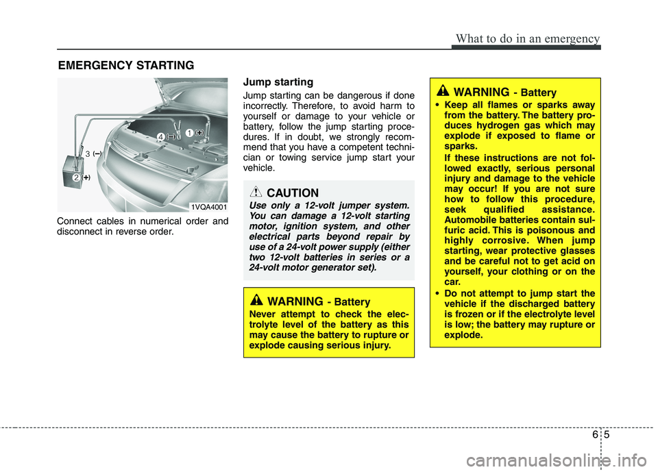
Connect cables in numerical order and
disconnect in reverse order. Jump starting
Jump starting can be dangerous if done
incorrectly. Therefore, to avoid harm to
yourself or damage to your vehicle or
battery, follow the jump starting proce-
dures. If in doubt, we strongly recom-
mend that you have a competent techni-
cian or towing service jump start your
vehicle.
CAUTION
Use only a 12-volt jumper system.
You can damage a 12-volt startingmotor, ignition system, and other
electrical parts beyond repair byuse of a 24-volt power supply (eithertwo 12-volt batteries in series or a24-volt motor generator set).
WARNING - Battery
• Keep all flames or sparks away from the battery. The battery pro-
duces hydrogen gas which may
explode if exposed to flame orsparks.
If these instructions are not fol-
lowed exactly, serious personal
injury and damage to the vehicle
may occur! If you are not sure
how to follow this procedure,
seek qualified assistance.
Automobile batteries contain sul-
furic acid. This is poisonous and
highly corrosive. When jump
starting, wear protective glasses
and be careful not to get acid on
yourself, your clothing or on the
car.
Do not attempt to jump start the vehicle if the discharged battery
is frozen or if the electrolyte level
is low; the battery may rupture or
explode.
WARNING - Battery
Never attempt to check the elec-
trolyte level of the battery as this
may cause the battery to rupture or
explode causing serious injury.
1VQA4001
Page 327 of 840
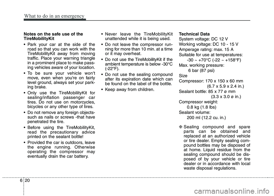
What to do in an emergency
20
6
Notes on the safe use of the TireMobilityKit
Park your car at the side of the
road so that you can work with the
TireMobilityKit away from moving
traffic. Place your warning triangle
in a prominent place to make pass-
ing vehicles aware of your location.
To be sure your vehicle won't move, even when you're on fairly
level ground, always set your park-
ing brake.
Only use the TireMobilityKit for sealing/inflation passenger car
tires. Do not use on motorcycles,
bicycles or any other type of tires.
Do not remove any foreign objects- such as nails or screws -that have
penetrated the tire.
Before using the TireMobilityKit, read the precautionary advice
printed on the sealant bottle!
Provided the car is outdoors, leave the engine running. Otherwise
operating the compressor may
eventually drain the car battery. Never leave the TireMobilityKit
unattended while it is being used.
Do not leave the compressor run- ning for more than 10 min. at a time
or it may overheat.
Do not use the TireMobilityKit if the ambient temperature is below -30°C(-22°F).
Do not use the sealing compound after its expiration date which can
be found on the label of the bottle.
Keep away from children. Technical Data
System voltage: DC 12 V
Working voltage: DC 10 - 15 V
Amperage rating: max. 15 A
Suitable for use at temperatures:
-30 ~ +70°C (-22 ~ +158°F)
Max. working pressure: 6 bar (87 psi)
Size
Compressor: 170 x 150 x 60 mm (6.7 x 5.9 x 2.4 in.)
Sealant bottle: 85 x 77 ø mm (3.3 x 3.0 ø in.)
Compressor weight: 0.8 kg (1.8 lbs)
Sealant volume: 200 ml (12.2 cu. in.)
❈ Sealing compound and spare
parts can be obtained and
replaced at an authorized vehicle
or tire dealer. Empty sealing com-
pound bottles may be disposed of
at home. Liquid residue from thesealing compound should be dis-
posed of by your vehicle or tiredealer or in accordance with local
waste disposal regulations.
Page 356 of 840
Maintenance
24
7
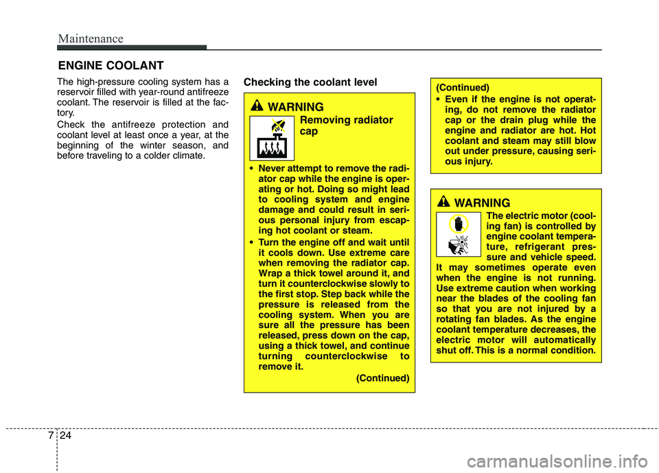
ENGINE COOLANT
The high-pressure cooling system has a
reservoir filled with year-round antifreeze
coolant. The reservoir is filled at the fac-
tory.
Check the antifreeze protection and
coolant level at least once a year, at thebeginning of the winter season, and
before traveling to a colder climate. Checking the coolant level
WARNING
Removing radiatorcap
Never attempt to remove the radi- ator cap while the engine is oper-
ating or hot. Doing so might leadto cooling system and engine
damage and could result in seri-
ous personal injury from escap-ing hot coolant or steam.
Turn the engine off and wait until it cools down. Use extreme care
when removing the radiator cap.
Wrap a thick towel around it, and
turn it counterclockwise slowly to
the first stop. Step back while the
pressure is released from the
cooling system. When you aresure all the pressure has been
released, press down on the cap,
using a thick towel, and continue
turning counterclockwise to
remove it.
(Continued)
(Continued)
Even if the engine is not operat-ing, do not remove the radiator cap or the drain plug while the
engine and radiator are hot. Hot
coolant and steam may still blow
out under pressure, causing seri-
ous injury.
WARNING
The electric motor (cool-
ing fan) is controlled byengine coolant tempera-
ture, refrigerant pres-
sure and vehicle speed.
It may sometimes operate evenwhen the engine is not running.
Use extreme caution when working
near the blades of the cooling fan
so that you are not injured by a
rotating fan blades. As the engine
coolant temperature decreases, the
electric motor will automatically
shut off. This is a normal condition.
Page 389 of 840
757
Maintenance
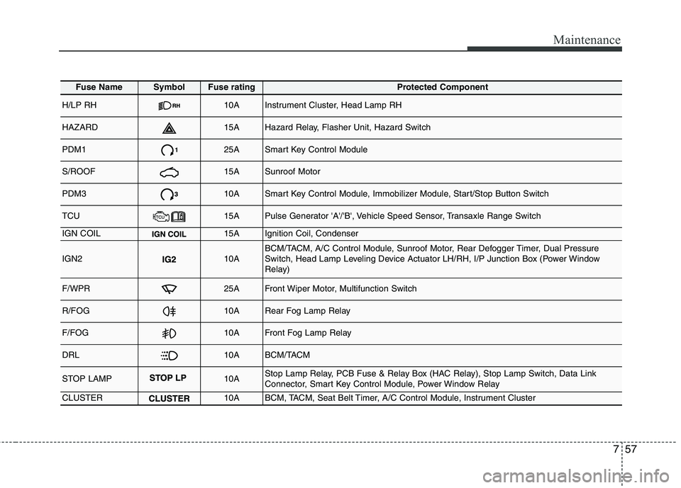
Fuse NameSymbolFuse ratingProtected Component
H/LP RH10AInstrument Cluster, Head Lamp RH
HAZARD15AHazard Relay, Flasher Unit, Hazard Switch
PDM125ASmart Key Control Module
S/ROOF15ASunroof Motor
PDM310ASmart Key Control Module, Immobilizer Module, Start/Stop Button Switch
TCU15APulse Generator 'A'/'B', Vehicle Speed Sensor, Transaxle Range Switch
IGN COIL15AIgnition Coil, Condenser
IGN210ABCM/TACM, A/C Control Module, Sunroof Motor, Rear Defogger Timer, Dual Pressure
Switch, Head Lamp Leveling Device Actuator LH/RH, I/P Junction Box (Power Window
Relay)
F/WPR25AFront Wiper Motor, Multifunction Switch
R/FOG10ARear Fog Lamp Relay
F/FOG10AFront Fog Lamp Relay
DRL10ABCM/TACM
STOP LAMP10AStop Lamp Relay, PCB Fuse & Relay Box (HAC Relay), Stop Lamp Switch, Data Link
Connector, Smart Key Control Module, Power Window Relay
CLUSTER10ABCM, TACM, Seat Belt Timer, A/C Control Module, Instrument Cluster
Page 390 of 840
Maintenance
58
7
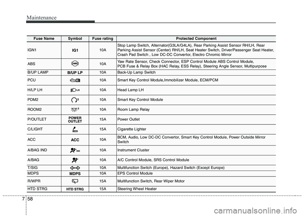
Fuse NameSymbolFuse ratingProtected Component
IGN110AStop Lamp Switch, Alternator(G3LA/G4LA), Rear Parking Assist Sensor RH/LH, Rear
Parking Assist Sensor (Center) RH/LH, Seat Heater Switch, Driver/Passenger Seat Heater,
Crash Pad Switch , Low DC-DC Convertor, Electro Chromic Mirror
ABS10AYaw Rate Sensor, Check Connector, ESP Control Module ABS Control Module,
PCB Fuse & Relay Box (HAC Relay, ESS Relay), Steering Angle Sensor, Multipurpose
B/UP LAMP10ABack-Up Lamp Switch
PCU10ASmart Key Control Module,Immobilizer Module, ECM/PCM
H/LP LH10AHead Lamp LH
PDM210ASmart Key Control Module
ROOM210ARoom Lamp Relay
P/OUTLET15APower Outlet
C/LIGHT15ACigarette Lighter
ACC10ABCM, Audio, Low DC-DC Convertor, Smart Key Control Module, Power Outside Mirror Switch
A/BAG IND10AInstrument Cluster
A/BAG10AA/C Control Module, SRS Control Module
T/SIG10AMultifunction Switch (Europe), Hazard Switch (Except Europe)
MDPS10AEPS Control Module
R/WPR15AMultifunction Switch, Rear Wiper Motor
HTD STRG15ASteering Wheel Heater
Page 392 of 840
Maintenance
60
7
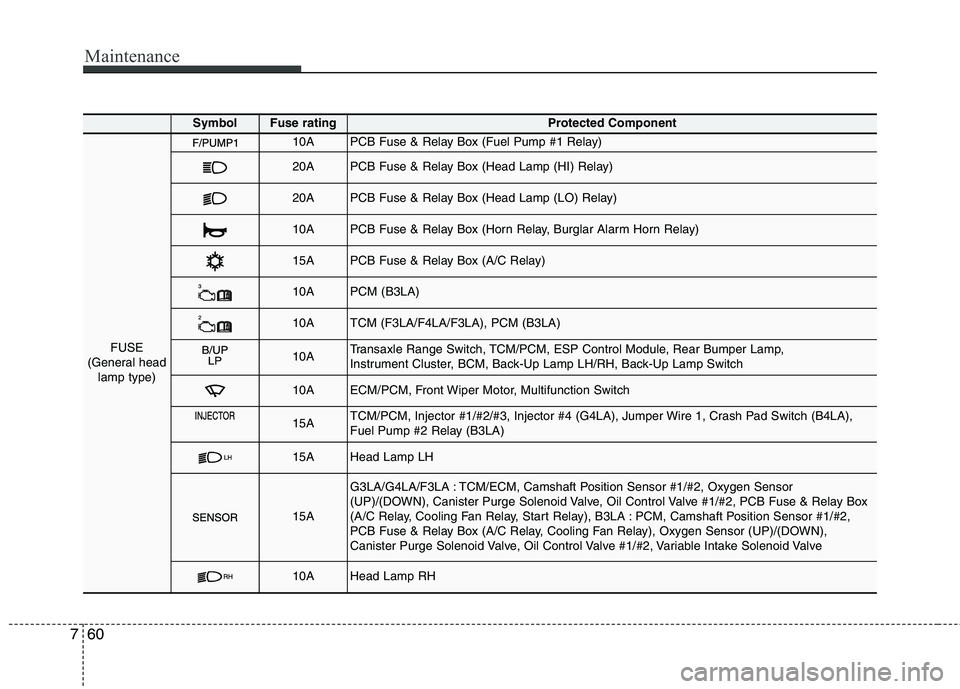
SymbolFuse ratingProtected Component
FUSE
(General head lamp type)
10APCB Fuse & Relay Box (Fuel Pump #1 Relay)
20APCB Fuse & Relay Box (Head Lamp (HI) Relay)
20APCB Fuse & Relay Box (Head Lamp (LO) Relay)
10APCB Fuse & Relay Box (Horn Relay, Burglar Alarm Horn Relay)
15APCB Fuse & Relay Box (A/C Relay)
10APCM (B3LA)
10ATCM (F3LA/F4LA/F3LA), PCM (B3LA)
10ATransaxle Range Switch, TCM/PCM, ESP Control Module, Rear Bumper Lamp,
Instrument Cluster, BCM, Back-Up Lamp LH/RH, Back-Up Lamp Switch
10AECM/PCM, Front Wiper Motor, Multifunction Switch
15ATCM/PCM, Injector #1/#2/#3, Injector #4 (G4LA), Jumper Wire 1, Crash Pad Switch (B4LA),
Fuel Pump #2 Relay (B3LA)
15AHead Lamp LH
15A
G3LA/G4LA/F3LA : TCM/ECM, Camshaft Position Sensor #1/#2, Oxygen Sensor
(UP)/(DOWN), Canister Purge Solenoid Valve, Oil Control Valve #1/#2, PCB Fuse & Relay Box
(A/C Relay, Cooling Fan Relay, Start Relay), B3LA : PCM, Camshaft Position Sensor #1/#2,
PCB Fuse & Relay Box (A/C Relay, Cooling Fan Relay), Oxygen Sensor (UP)/(DOWN),
Canister Purge Solenoid Valve, Oil Control Valve #1/#2, Variable Intake Solenoid Valve
10AHead Lamp RH
Page 393 of 840
761
Maintenance
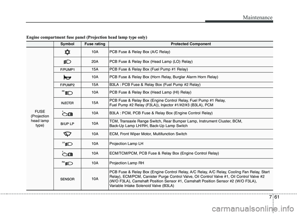
Engine compartment fuse panel (Projection head lamp type only)
SymbolFuse ratingProtected Component
FUSE
(Projection head lamp
type)
10APCB Fuse & Relay Box (A/C Relay)
20APCB Fuse & Relay Box (Head Lamp (LO) Relay)
15APCB Fuse & Relay Box (Fuel Pump #1 Relay)
10APCB Fuse & Relay Box (Horn Relay, Burglar Alarm Horn Relay)
15AB3LA : PCB Fuse & Relay Box (Fuel Pump #2 Relay)
10APCB Fuse & Relay Box (Head Lamp (HI) Relay)
15APCB Fuse & Relay Box (Engine Control Relay, Fuel Pump #1 Relay,
Fuel Pump #2 Relay (F3LA)), Injector #1/#2/#3 (B3LA), PCM
10AB3LA : PCM, PCB Fuse & Relay Box (Engine Control Relay)
10ATCM, Transaxle Range Switch, Rear Bumper Lamp, Instrument Cluster, BCM,
Back-Up Lamp LH/RH, Back-Up Lamp Switch
10AECM, Front Wiper Motor, Multifunction Switch
10AProjection Lamp LH
10AECM/TCM/PCM, PCB Fuse & Relay Box (Engine Control Relay)
10AProjection Lamp RH
10A
PCB Fuse & Relay Box (Engine Control Relay, A/C Relay, A/C Relay, Cooling Fan Relay, Start
Relay), ECM/PCM, Canister Purge Control Valve, Oil Control Valve #1, Oil Control Valve #2
(W/O F3LA), Camshaft Position Sensor #1, Camshaft Position Sensor #2 (W/O F3LA),
Variable Intake Solenoid Valve (B3LA)