clock KIA QUORIS 2013 Owners Manual
[x] Cancel search | Manufacturer: KIA, Model Year: 2013, Model line: QUORIS, Model: KIA QUORIS 2013Pages: 485, PDF Size: 31.55 MB
Page 13 of 485
25
Your vehicle at a glance
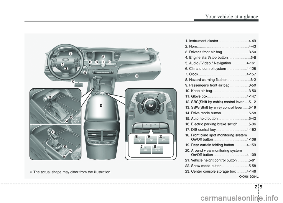
1. Instrument cluster ..............................4-49
2. Horn...................................................4-43
3. Driver's front air bag ..........................3-50
4. Engine start/stop button ......................5-6
5. Audio / Video / Navigation ...............4-161
6. Climate control system ....................4-128
7. Clock................................................4-157
8. Hazard warning flasher .......................6-2
9. Passenger's front air bag...................3-50
10. Knee air bag ....................................3-50
11. Glove box.......................................4-147
12. SBC(Shift by cable) control lever.....5-12
13. SBW(Shift by wire) control lever......5-19
14. Drive mode button ...........................5-58
15. Auto hold button ..............................5-42
16. Electric parking brake switch ...........5-36
17. DIS central key ..............................4-162
18. Front blind spot monitoring systemOn/Off button .................................4-108
19. Rear curtain folding button ............4-159
20. Around view monitoring system On/Off button .................................4-109
21. Vehicle height control button ...........5-61
22. Snow mode button ..........................5-58
23. Center console storage box ..........4-146 OKH012004L
❈The actual shape may differ from the illustration.
Page 94 of 485
415
Features of your vehicle
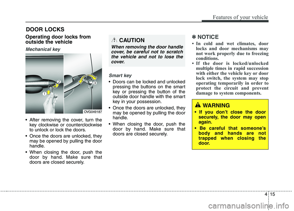
Operating door locks from
outside the vehicle
Mechanical key
After removing the cover, turn thekey clockwise or counterclockwise
to unlock or lock the doors.
Once the doors are unlocked, they may be opened by pulling the door
handle.
When closing the door, push the door by hand. Make sure that
doors are closed securely.
Smart key
Doors can be locked and unlockedpressing the buttons on the smart
key or pressing the button of the
outside door handle with the smart
key in your possession.
Once the doors are unlocked, they may be opened by pulling the door
handle.
When closing the door, push the door by hand. Make sure that
doors are closed securely.
✽✽ NOTICE
In cold and wet climates, door locks and door mechanisms may
not work properly due to freezing
conditions.
If the door is locked/unlocked multiple times in rapid succession
with either the vehicle key or door
lock switch, the system may stop
operating temporarily in order to
protect the circuit and prevent
damage to system components.
DOOR LOCKS
OVG049187
WARNING
securely, the door may open
again.
body and hands are not
trapped when closing the
door.
CAUTION
When removing the door handle
cover, be careful not to scratchthe vehicle and not to lose the cover.
Page 99 of 485
Features of your vehicle
20
4
TRUNK
Non-powered trunk
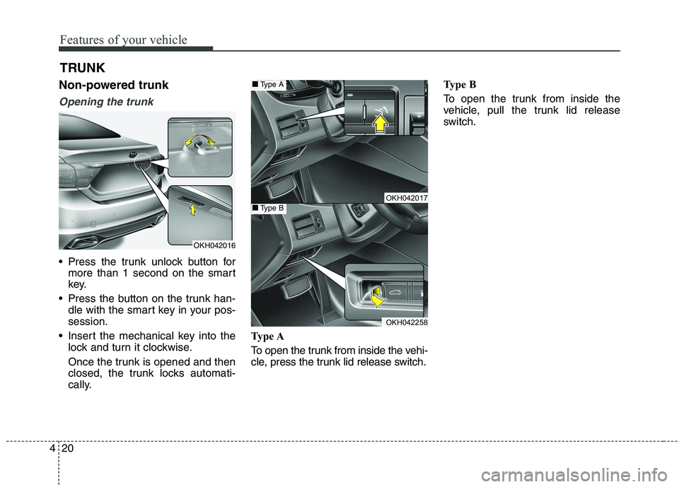
Opening the trunk
Press the trunk unlock button for more than 1 second on the smart
key.
Press the button on the trunk han- dle with the smart key in your pos- session.
Insert the mechanical key into the lock and turn it clockwise.
Once the trunk is opened and then
closed, the trunk locks automati-
cally. Type A
To open the trunk from inside the vehi-
cle, press the trunk lid release switch. Type B
To open the trunk from inside the
vehicle, pull the trunk lid release
switch.
OKH042016
OKH042017
OKH042258
■■
Type A
■■Type B
Page 113 of 485
Features of your vehicle
34
4
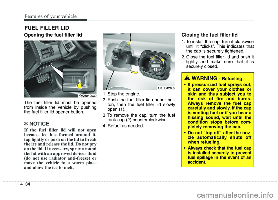
Opening the fuel filler lid
The fuel filler lid must be opened
from inside the vehicle by pushing
the fuel filler lid opener button.
✽✽
NOTICE
If the fuel filler lid will not open
because ice has formed around it,
tap lightly or push on the lid to break
the ice and release the lid. Do not pry
on the lid. If necessary, spray around
the lid with an approved de-icer fluid
(do not use radiator anti-freeze) or
move the vehicle to a warm place
and allow the ice to melt.
1. Stop the engine.
2. Push the fuel filler lid opener but- ton, then the fuel filler lid slowly open (1).
3. To remove the cap, turn the fuel tank cap (2) counterclockwise.
4. Refuel as needed. Closing the fuel filler lid
1. To install the cap, turn it clockwise
until it “clicks”. This indicates that the cap is securely tightened.
2. Close the fuel filler lid and push it lightly and make sure that it issecurely closed.
FUEL FILLER LID OKH042030
OKH042032
WARNING
- Refueling
If pressurized fuel sprays out, it can cover your clothes or
skin and thus subject you to
the risk of fire and burns.
Always remove the fuel cap
carefully and slowly. If the cap
is venting fuel or if you hear a
hissing sound, wait until the
condition stops before com-
pletely removing the cap.
Do not "top off" after the noz- zle automatically shuts offwhen refueling.
Always check that the fuel cap is installed securely to prevent
fuel spillage in the event of anaccident.
Page 236 of 485
4157
Features of your vehicle
Clock
You can set the clock by using the
AVN (Audio or Navigation)
For the details, refer to the AVN man- ual.Clothes hanger (if equipped)
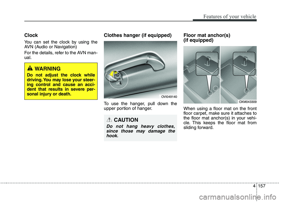
To use the hanger, pull down the
upper portion of hanger.Floor mat anchor(s) (if equipped) When using a floor mat on the front
floor carpet, make sure it attaches to
the floor mat anchor(s) in your vehi-
cle. This keeps the floor mat from
sliding forward.
WARNING
Do not adjust the clock while
driving. You may lose your steer-
ing control and cause an acci-
dent that results in severe per-
sonal injury or death.
OVI049140
CAUTION
Do not hang heavy clothes,
since those may damage thehook.
OXM043309
Page 268 of 485
![KIA QUORIS 2013 Owners Manual 525
Driving your vehicle
■■When the battery is dis-charged:
When the battery is discharged, the
automatic transmission (shift by wire)is not shifted.
In emergency, if you want to shift into
[N] KIA QUORIS 2013 Owners Manual 525
Driving your vehicle
■■When the battery is dis-charged:
When the battery is discharged, the
automatic transmission (shift by wire)is not shifted.
In emergency, if you want to shift into
[N]](/img/2/57975/w960_57975-267.png)
525
Driving your vehicle
■■When the battery is dis-charged:
When the battery is discharged, the
automatic transmission (shift by wire)is not shifted.
In emergency, if you want to shift into
[N], follow actions
You can shift into [N] by using the
driver if the jump starting is impossi-
ble to do.
1) Open the storage cover.
2) Remove the rubber on bottom ofstorage box.
3) Insert the driver (-) to service hole as direction of clockwise 10 times. The shifting is changed to [N] from
[P] position. If you want to shift to
[P] position, turn the driver count-
er-clockwise.
OKH052045L
CAUTION
If the electric parking brake is
not released, we recommendthat the vehicle is towed as flat-bed towing.
Page 364 of 485
What to do in an emergency
16
6
Removing and storing the spare tire
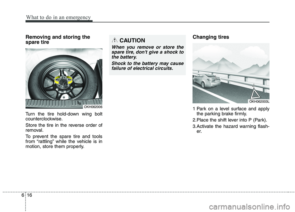
Turn the tire hold-down wing bolt
counterclockwise.
Store the tire in the reverse order of
removal.
To prevent the spare tire and tools
from “rattling” while the vehicle is in
motion, store them properly. Changing tires
1 Park on a level surface and apply
the parking brake firmly.
2.Place the shift lever into P (Park).
3.Activate the hazard warning flash- er.
OKH062006
OKH062003L
CAUTION
When you remove or store the
spare tire, don't give a shock tothe battery.
Shock to the battery may causefailure of electrical circuits.
Page 366 of 485
What to do in an emergency
18
6
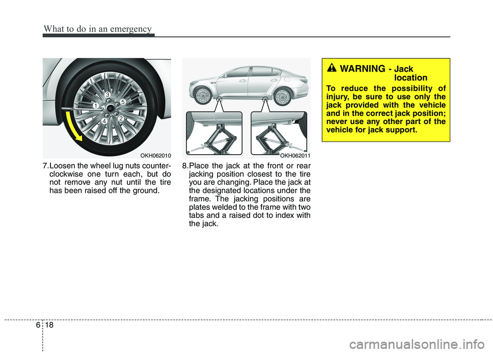
7.Loosen the wheel lug nuts counter-
clockwise one turn each, but do
not remove any nut until the tire
has been raised off the ground. 8.Place the jack at the front or rear
jacking position closest to the tire
you are changing. Place the jack atthe designated locations under the
frame. The jacking positions are
plates welded to the frame with two
tabs and a raised dot to index with
the jack.
OKH062010OKH062011
WARNING - Jack
location
To reduce the possibility of
injury, be sure to use only the
jack provided with the vehicle
and in the correct jack position;
never use any other part of the
vehicle for jack support.
Page 367 of 485
619
What to do in an emergency
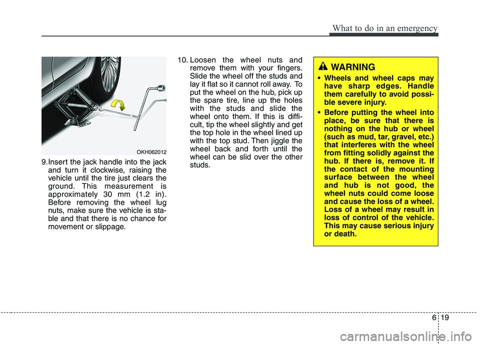
9.Insert the jack handle into the jackand turn it clockwise, raising the
vehicle until the tire just clears the
ground. This measurement is
approximately 30 mm (1.2 in).
Before removing the wheel lug
nuts, make sure the vehicle is sta-
ble and that there is no chance for
movement or slippage. 10. Loosen the wheel nuts and
remove them with your fingers.Slide the wheel off the studs and
lay it flat so it cannot roll away. To
put the wheel on the hub, pick up
the spare tire, line up the holeswith the studs and slide the
wheel onto them. If this is diffi-cult, tip the wheel slightly and getthe top hole in the wheel lined up
with the top stud. Then jiggle the
wheel back and forth until the
wheel can be slid over the other
studs.
OKH062012
WARNING
Wheels and wheel caps may have sharp edges. Handle
them carefully to avoid possi-
ble severe injury.
Before putting the wheel into place, be sure that there isnothing on the hub or wheel
(such as mud, tar, gravel, etc.)
that interferes with the wheel
from fitting solidly against the
hub. If there is, remove it. Ifthe contact of the mountingsurface between the wheel
and hub is not good, the
wheel nuts could come looseand cause the loss of a wheel.
Loss of a wheel may result in
loss of control of the vehicle.
This may cause serious injuryor death.
Page 368 of 485
What to do in an emergency
20
6
11. To reinstall the wheel, hold it on
the studs, put the wheel nuts on the studs and tighten them finger
tight. The nuts should be installedwith their tapered small diameter
ends directed inward. Jiggle thetire to be sure it is completely
seated, then tighten the nuts as
much as possible with your fin-gers again.
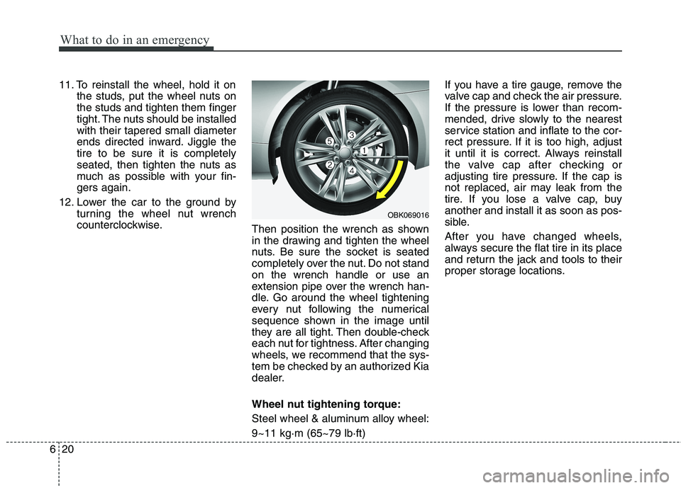
12. Lower the car to the ground by turning the wheel nut wrench
counterclockwise. Then position the wrench as shown
in the drawing and tighten the wheel
nuts. Be sure the socket is seated
completely over the nut. Do not standon the wrench handle or use an
extension pipe over the wrench han-
dle. Go around the wheel tightening
every nut following the numerical
sequence shown in the image until
they are all tight. Then double-check
each nut for tightness. After changing
wheels, we recommend that the sys-
tem be checked by an authorized Kia
dealer.
Wheel nut tightening torque:
Steel wheel & aluminum alloy wheel:9~11 kg·m (65~79 lb·ft) If you have a tire gauge, remove the
valve cap and check the air pressure.
If the pressure is lower than recom-
mended, drive slowly to the nearest
service station and inflate to the cor-
rect pressure. If it is too high, adjust
it until it is correct. Always reinstall
the valve cap after checking or
adjusting tire pressure. If the cap is
not replaced, air may leak from the
tire. If you lose a valve cap, buyanother and install it as soon as pos-
sible.
After you have changed wheels,
always secure the flat tire in its place
and return the jack and tools to their
proper storage locations.
OBK069016