clock KIA Rondo 2017 3.G Owner's Guide
[x] Cancel search | Manufacturer: KIA, Model Year: 2017, Model line: Rondo, Model: KIA Rondo 2017 3.GPages: 625, PDF Size: 19.69 MB
Page 489 of 625
What to do in an emergency
18
7
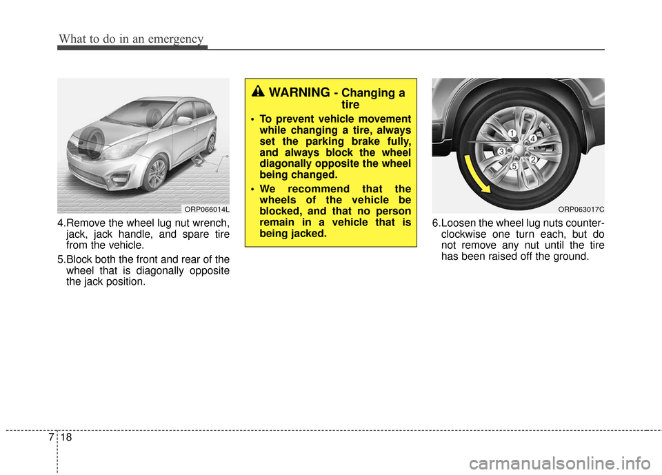
4.Remove the wheel lug nut wrench,
jack, jack handle, and spare tire
from the vehicle.
5.Block both the front and rear of the wheel that is diagonally opposite
the jack position. 6.Loosen the wheel lug nuts counter-
clockwise one turn each, but do
not remove any nut until the tire
has been raised off the ground.
ORP066014LORP063017C
WARNING - Changing atire
To prevent vehicle movement
while changing a tire, always
set the parking brake fully,
and always block the wheel
diagonally opposite the wheel
being changed.
We recommend that the wheels of the vehicle be
blocked, and that no person
remain in a vehicle that is
being jacked.
Page 490 of 625
719
What to do in an emergency
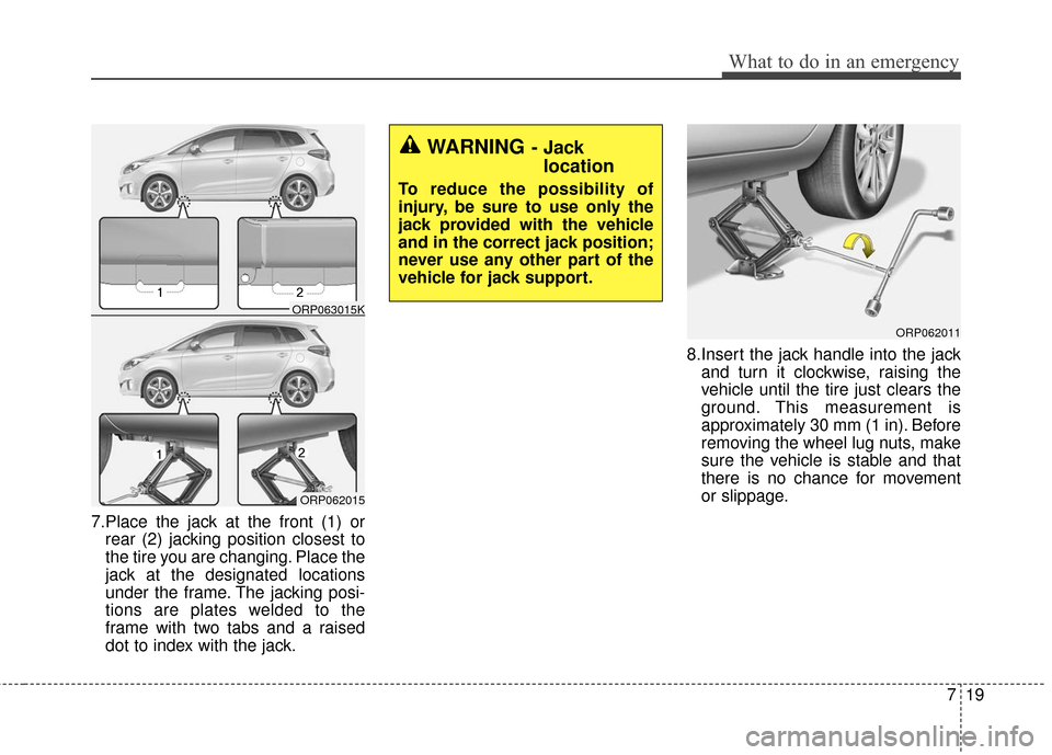
7.Place the jack at the front (1) orrear (2) jacking position closest to
the tire you are changing. Place the
jack at the designated locations
under the frame. The jacking posi-
tions are plates welded to the
frame with two tabs and a raised
dot to index with the jack. 8.Insert the jack handle into the jack
and turn it clockwise, raising the
vehicle until the tire just clears the
ground. This measurement is
approximately 30 mm (1 in). Before
removing the wheel lug nuts, make
sure the vehicle is stable and that
there is no chance for movement
or slippage.
ORP062011
WARNING- Jack location
To reduce the possibility of
injury, be sure to use only the
jack provided with the vehicle
and in the correct jack position;
never use any other part of the
vehicle for jack support.
ORP062015
ORP063015K
Page 491 of 625
What to do in an emergency
20
7
9.Loosen the wheel nuts and remove
them with your fingers. Slide the
wheel off the studs and lay it flat so
it cannot roll away. To put the
wheel on the hub, pick up the
spare tire, line up the holes with
the studs and slide the wheel onto
them. If this is difficult, tip the wheel
slightly and get the top hole in the
wheel lined up with the top stud.
Then jiggle the wheel back and
forth until the wheel can be slid
over the other studs. 10. To install the wheel, hold it on the
studs, put the wheel nuts on the
studs and tighten them finger
tight. Jiggle the tire to be sure it is
completely seated, then tighten
the nuts as much as possible
with your fingers again.
11. Lower the vehicle to the ground by turning the wheel nut wrench
counterclockwise.
WARNING
Wheels may have sharp edges.
Handle them carefully to avoid
possible severe injury. Before
putting the wheel into place, be
sure that there is nothing on the
hub or wheel (such as mud, tar,
gravel, etc.) that prevents the
wheel from fitting solidly
against the hub.
If there is, remove it. If the con-
tact of the mounting surface
between the wheel and hub is
not good, the wheel nuts could
come loose and cause the loss
of a wheel. Loss of a wheel may
result in loss of control of the
vehicle. This may cause serious
injury or death.
Page 497 of 625
What to do in an emergency
26
7
When towing your vehicle in an
emergency without wheel dollies :
1.Set the ignition switch in the ACC
position.
2.Place the transaxle shift lever in N (Neutral).
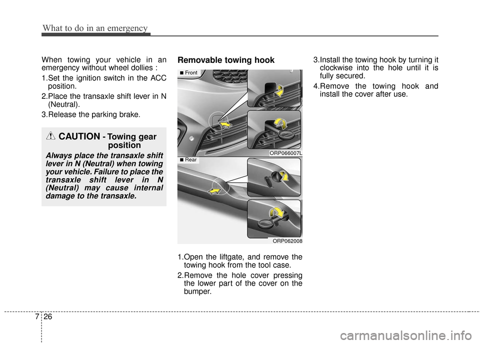
3.Release the parking brake.Removable towing hook
1.Open the liftgate, and remove the towing hook from the tool case.
2.Remove the hole cover pressing the lower part of the cover on the
bumper. 3.Install the towing hook by turning it
clockwise into the hole until it is
fully secured.
4.Remove the towing hook and install the cover after use.
CAUTION- Towing gear position
Always place the transaxle shift
lever in N (Neutral) when towingyour vehicle. Failure to place thetransaxle shift lever in N(Neutral) may cause internaldamage to the transaxle.ORP066007L
ORP062008
■Front
■Rear
Page 531 of 625
831
Maintenance
ENGINE COOLANT
The high-pressure cooling system
has a reservoir filled with year-round
antifreeze coolant. The reservoir is
filled at the factory.
Check the antifreeze protection and
coolant level at least once a year, at
the beginning of the winter season,
and before traveling to a colder cli-
mate.Checking the coolant level
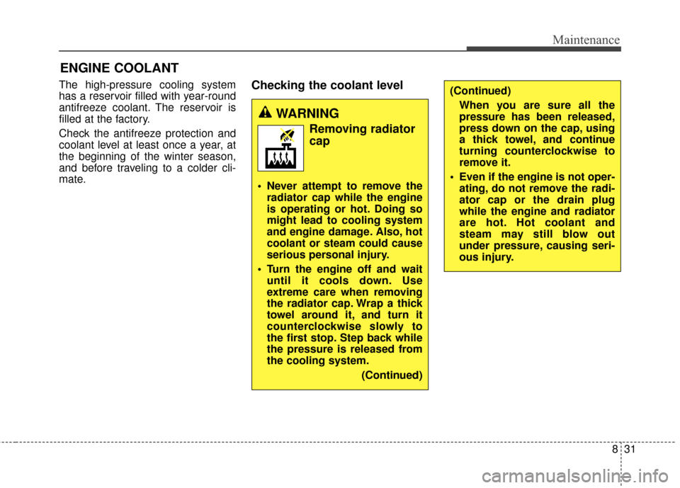
WARNING
Removing radiatorcap
Never attempt to remove the
radiator cap while the engine
is operating or hot. Doing so
might lead to cooling system
and engine damage. Also, hot
coolant or steam could cause
serious personal injury.
Turn the engine off and wait until it cools down. Use
extreme care when removing
the radiator cap. Wrap a thick
towel around it, and turn it
counterclockwise slowly to
the first stop. Step back while
the pressure is released from
the cooling system.
(Continued)
(Continued)When you are sure all the
pressure has been released,
press down on the cap, using
a thick towel, and continue
turning counterclockwise to
remove it.
Even if the engine is not oper- ating, do not remove the radi-
ator cap or the drain plug
while the engine and radiator
are hot. Hot coolant and
steam may still blow out
under pressure, causing seri-
ous injury.
Page 569 of 625
869
Maintenance
Fuse switch
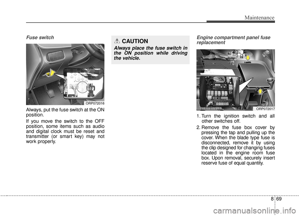
Always, put the fuse switch at the ON
position.
If you move the switch to the OFF
position, some items such as audio
and digital clock must be reset and
transmitter (or smart key) may not
work properly.
Engine compartment panel fusereplacement
1. Turn the ignition switch and all other switches off.
2. Remove the fuse box cover by pressing the tap and pulling up the
cover. When the blade type fuse is
disconnected, remove it by using
the clip designed for changing fuses
located in the engine room fuse
box. Upon removal, securely insert
reserve fuse of equal quantity.
ORP072016
CAUTION
Always place the fuse switch inthe ON position while drivingthe vehicle.
ORP072017
Page 575 of 625
875
Maintenance
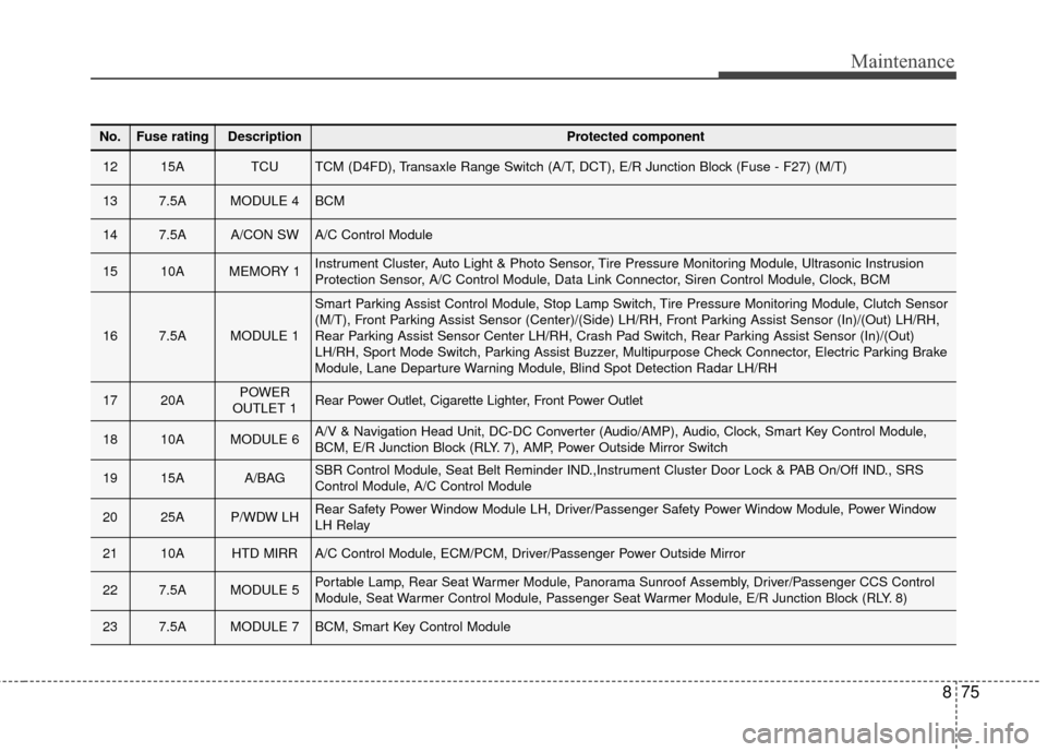
No.Fuse ratingDescriptionProtected component
1215ATCUTCM (D4FD), Transaxle Range Switch (A/T, DCT), E/R Junction Block (Fuse - F27) (M/T)
137.5AMODULE 4BCM
147.5AA/CON SWA/C Control Module
1510AMEMORY 1Instrument Cluster, Auto Light & Photo Sensor, Tire Pressure Monitoring Module, Ultrasonic Instrusion
Protection Sensor, A/C Control Module, Data Link Connector, Siren Control Module, Clock, BCM
167.5AMODULE 1
Smart Parking Assist Control Module, Stop Lamp Switch, Tire Pressure Monitoring Module, Clutch Sensor
(M/T), Front Parking Assist Sensor (Center)/(Side) LH/RH, Front Parking Assist Sensor (In)/(Out) LH/RH,
Rear Parking Assist Sensor Center LH/RH, Crash Pad Switch, Rear Parking Assist Sensor (In)/(Out)
LH/RH, Sport Mode Switch, Parking Assist Buzzer, Multipurpose Check Connector, Electric Parking Brake
Module, Lane Departure Warning Module, Blind Spot Detection Radar LH/RH
1720APOWER
OUTLET 1Rear Power Outlet, Cigarette Lighter, Front Power Outlet
1810AMODULE 6A/V & Navigation Head Unit, DC-DC Converter (Audio/AMP), Audio, Clock, Smart Key Control Module,
BCM, E/R Junction Block (RLY. 7), AMP, Power Outside Mirror Switch
1915AA/BAGSBR Control Module, Seat Belt Reminder IND.,Instrument Cluster Door Lock & PAB On/Off IND., SRS
Control Module, A/C Control Module
2025AP/WDW LHRear Safety Power Window Module LH, Driver/Passenger Safety Power Window Module, Power Window
LH Relay
2110AHTD MIRRA/C Control Module, ECM/PCM, Driver/Passenger Power Outside Mirror
227.5AMODULE 5Portable Lamp, Rear Seat Warmer Module, Panorama Sunroof Assembly, Driver/Passenger CCS Control
Module, Seat Warmer Control Module, Passenger Seat Warmer Module, E/R Junction Block (RLY. 8)
237.5AMODULE 7BCM, Smart Key Control Module
Page 582 of 625
Maintenance
82
8
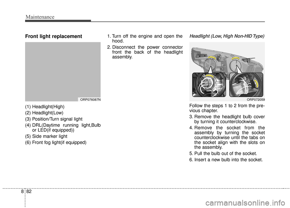
Front light replacement
(1) Headlight(High)
(2) Headlight(Low)
(3) Position/Turn signal light
(4) DRL(Daytime running light,Bulb
or LED(if equipped))
(5) Side marker light
(6) Front fog light(if equipped) 1. Turn off the engine and open the
hood.
2. Disconnect the power connector front the back of the headlight
assembly.
Headlight (Low, High Non-HID Type)
Follow the steps 1 to 2 from the pre-
vious chapter.
3. Remove the headlight bulb coverby turning it counterclockwise.
4. Remove the socket from the assembly by turning the socket
counterclockwise until the tabs on
the socket align with the slots on
the assembly.
5. Pull the bulb out of the socket.
6. Insert a new bulb into the socket.
ORP076087NORP072059
Page 583 of 625
883
Maintenance
7. Install the socket in the assemblyby aligning the tabs on the socket
with the slots in the assembly.
Push the socket into the assembly
and turn the socket clockwise.
8. Install the headlight bulb cover by turning it clockwise.
9. Connect the power connector to the back of the headlight assem-
bly.
✽ ✽NOTICE
If the headlight aiming adjustment
is necessary after the headlight
assembly is reinstalled, have the
vehicle checked by an authorized
Kia dealer.
Headlight (Low, HID type),
DRL (LED type)
If the DRL lamp (LED) does not
operate, have the vehicle checked by
an authorized Kia dealer.
LED lamps do not have replaceable
bulbs.
A skilled technician should check or
repair the Headlight low (HID) and
DRL lamp(LED), for it may damage
related parts of the vehicle.
✽ ✽ NOTICE
HID lamps have superior perform-
ance vs. halogen bulbs. HID lamps
are estimated by the manufacturer to
last twice as long or longer than halo-
gen bulbs depending on their fre-
quency of use. They will probably
require replacement at some point in
the life of the vehicle. Cycling the
headlamps on and off more than typ-
ical use will shorten HID lamps life.
HID lamps do not fail in the same
manner as halogen incandescent
lamps. If a headlamp goes out after a
period of operation but will immedi-
ately relight when the headlamp
switch is cycled it is likely the HID
lamp needs to be replaced. HID light-
ing components are more complex
than conventional halogen bulbs thus
have higher replacement cost.
WARNING - HID
Headlight low beam
(if equipped)
Do not attempt to replace or
inspect the low beam (XENON
bulb) due to electric shock dan-
ger. If the low beam (XENON
bulb) is not working, have the
vehicle checked by an author-
ized Kia dealer.
Page 584 of 625
Maintenance
84
8
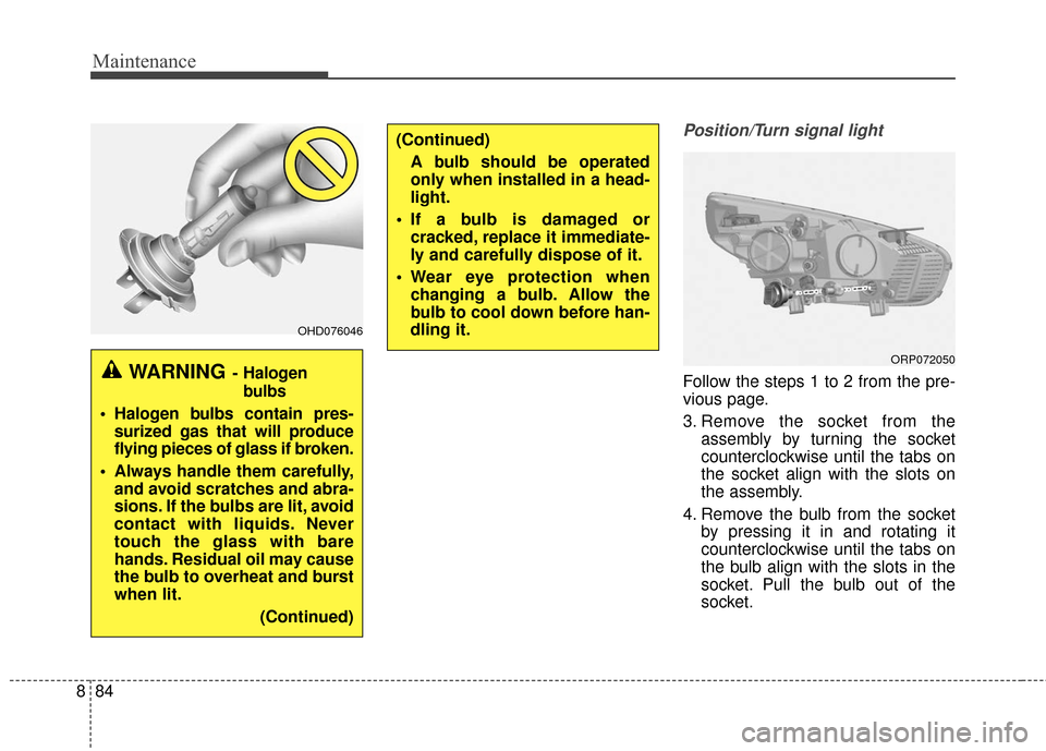
Position/Turn signal light
Follow the steps 1 to 2 from the pre-
vious page.
3. Remove the socket from the
assembly by turning the socket
counterclockwise until the tabs on
the socket align with the slots on
the assembly.
4. Remove the bulb from the socket by pressing it in and rotating it
counterclockwise until the tabs on
the bulb align with the slots in the
socket. Pull the bulb out of the
socket.
OHD076046
WARNING- Halogen
bulbs
Halogen bulbs contain pres-surized gas that will produce
flying pieces of glass if broken.
Always handle them carefully, and avoid scratches and abra-
sions. If the bulbs are lit, avoid
contact with liquids. Never
touch the glass with bare
hands. Residual oil may cause
the bulb to overheat and burst
when lit.
(Continued)
(Continued)A bulb should be operated
only when installed in a head-
light.
If a bulb is damaged or cracked, replace it immediate-
ly and carefully dispose of it.
Wear eye protection when changing a bulb. Allow the
bulb to cool down before han-
dling it.
ORP072050