turn signal KIA Sorento 2008 1.G Owner's Manual
[x] Cancel search | Manufacturer: KIA, Model Year: 2008, Model line: Sorento, Model: KIA Sorento 2008 1.GPages: 326, PDF Size: 8.63 MB
Page 8 of 326
Your vehicle at a glance
2 2
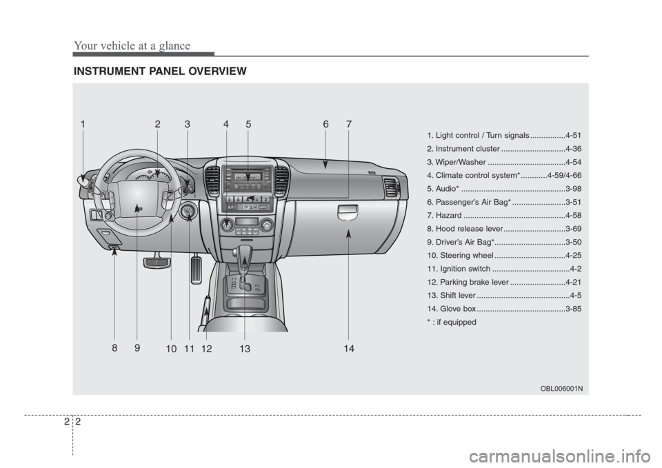
INSTRUMENT PANEL OVERVIEW
OBL006001N
1. Light control / Turn signals ................4-51
2. Instrument cluster .............................4-36
3. Wiper/Washer ...................................4-54
4. Climate control system* ............4-59/4-66
5. Audio* ...............................................3-98
6. Passenger’s Air Bag* ........................3-51
7. Hazard ..............................................4-58
8. Hood release lever ............................3-69
9. Driver’s Air Bag*................................3-50
10. Steering wheel ................................4-25
11. Ignition switch ...................................4-2
12. Parking brake lever .........................4-21
13. Shift lever ..........................................4-5
14. Glove box ........................................3-85
* : if equipped
1234567
89
1011121314
Page 14 of 326
35
Knowing your vehicle
Your vehicle is equipped with an electron-
ic engine immobilizer system to reduce
the risk of unauthorized vehicle use.
Your immobilizer system is comprised of
a small transponder in the ignition key,
and antenna coil in the key cylinder and
Immobilizer Control Unit (or Smartra
Unit).
With this system, whenever you insert
your ignition key into the ignition switch
and turn it to ON, the antenna coil in the
ignition switch receives a signal from the
transponder in the ignition key and then
sends the signal to the ECU (Engine
Control Unit).
The ECU checks the signal whether the
ignition key is valid.
If the key is determined to be valid, the
engine will start.
If the key is determined to be invalid, the
engine will not start.
To deactivate the immobilizer system:
Insert the ignition key into the key cylin-
der and turn it to the ON position.
To activate the immobilizer system:
Turn the ignition key to the OFF position.
The immobilizer system activates auto-
matically. Without a valid ignition key for
your vehicle, the engine will not start.
✽
NOTICE
When starting the engine, do not use the
key with other immobilizer keys around.
Otherwise the engine may not start or
may stop soon after it starts. Keep each
key separately not to have any malfunc-
tion after you receive your new vehicle.
Limp home (override) procedure
When you turn the ignition key to the ON
position, if the IMMO indicator goes off
after blinking 5 times, your transponder
equipped in the ignition key is out of order.
You cannot start the engine without the
lime home procedure. To start the engine,
you have to input your password by using
the ignition switch.
The following procedure is how to input
your password of “2345” as an example.
1. Turn the ignition key to the ON position.
The IMMO indicator ( ) will blink 5
times and go off indicating the begin-
ning of the limp home procedure.
2. Turn the ignition key to the ACC posi-
tion.
3. To enter the first digit (in this example
“2”), turn the ignition key to the ON and
ACC position twice. Perform the same
procedure for the next digits between 3
seconds and 10 seconds (for example,
for “3”, turn the ignition ON and ACC 3
times).
IMMOBILIZER SYSTEM (IF EQUIPPED)
CAUTION
Do not put metal accessories near
the key or ignition switch.
The engine may not start for the
metal accessories may interrupt the
transponder signal from normally
transmitting.
WARNING
In order to prevent theft of your
vehicle, do not leave spare keys
anywhere in your vehicle. Your
Immobilizer password is a cus-
tomer unique password and should
be kept confidential. Do not leave
this number anywhere in your vehi-
cle.
Page 73 of 326
Knowing your vehicle
64 3
How does the air bag system
operate
• Air bag only operates when the ignition
switch is turned to ON or START posi-
tion.
• Air bags inflate instantly in the event of
serious frontal or side collision in order
to help protect the occupants from seri-
ous physical injury.
• There is no single speed at which the
air bags will inflate.
Generally, air bags are designed to
inflate by the severity of a collision and
its direction. These two factors deter-
mine whether the sensors send out an
electronic deployment/inflation signal.
• Air bag deployment depends on a
number of factors including vehicle
speed, angles of impact and the densi-
ty and stiffness of the vehicles or
objects which your vehicle hits in the
collision. Though, factors are not limit-
ed to those mentioned above.
• The front air bags will completely
inflate and deflate in an instant.
It is virtually impossible for you to see
the air bags inflate during an accident.
It is much more likely that you will sim-
ply see the deflated air bags hanging
out of their storage compartments after
the collision.• In order to help provide protection in a
severe collision, the air bags must
inflate rapidly. The speed of air bag
inflation has been determined by the
Canadian Motor Vehicle Safety
Standards (CMVSS) to reduce the like-
lihood of serious or life-threatening
injuries and is thus a mandatory part of
the air bag design.
However, air bag inflation can also
cause injuries which normally can
include facial abrasions, bruises and
broken bones, and sometimes more
serious injuries because the inflation
speed also causes the air bags to
expand with a great deal of force.
• There are even circumstances
under which contact with the steer-
ing wheel air bag can cause fatal
injuries,especially if the occupant
is positioned excessively close to
the steering wheel.
WARNING
• To avoid severe personal injury or
death caused by deploying air
bags in a collision, the driver
should sit as far back from the
steering wheel air bag as possi-
ble (at least 250 mm (10 inches)
away). The front passenger
should always move their seat as
far back as possible and sit back
in their seat.
• Air bag inflates instantly in an
event of collision, passengers
may be injured by the air bag
expansion force if they are not in
proper position.
• Air bag inflation may cause
injuries which normally include
facial or bodily abrasions, injuries
by broken glass or burns by the
explosives.
Page 87 of 326
Knowing your vehicle
78 3
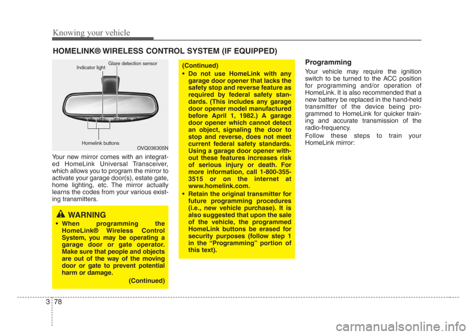
Your new mirror comes with an integrat-
ed HomeLink Universal Transceiver,
which allows you to program the mirror to
activate your garage door(s), estate gate,
home lighting, etc. The mirror actually
learns the codes from your various exist-
ing transmitters.
Programming
Your vehicle may require the ignition
switch to be turned to the ACC position
for programming and/or operation of
HomeLink. It is also recommended that a
new battery be replaced in the hand-held
transmitter of the device being pro-
grammed to HomeLink for quicker train-
ing and accurate transmission of the
radio-frequency.
Follow these steps to train your
HomeLink mirror:
HOMELINK® WIRELESS CONTROL SYSTEM (IF EQUIPPED)
WARNING
• When programming the
HomeLink® Wireless Control
System, you may be operating a
garage door or gate operator.
Make sure that people and objects
are out of the way of the moving
door or gate to prevent potential
harm or damage.
(Continued)
(Continued)
• Do not use HomeLink with any
garage door opener that lacks the
safety stop and reverse feature as
required by federal safety stan-
dards. (This includes any garage
door opener model manufactured
before April 1, 1982.) A garage
door opener which cannot detect
an object,signaling the door to
stop and reverse, does not meet
current federal safety standards.
Using a garage door opener with-
out these features increases risk
of serious injury or death. For
more information, call 1-800-355-
3515 or on the internet at
www.homelink.com.
• Retain the original transmitter for
future programming procedures
(i.e., new vehicle purchase). It is
also suggested that upon the sale
of the vehicle, the programmed
HomeLink buttons be erased for
security purposes (follow step 1
in the “Programming” portion of
this text).
OVQ036305N Glare detection sensor
Indicator light
Homelink buttons
Page 89 of 326
Knowing your vehicle
80 3
Rolling code programming
To train a garage door opener (or other
rolling code equipped devices) with the
rolling code feature, follow these instruc-
tions after completing the “Programming”
portion of this text. (A second person
may make the following training proce-
dures quicker & easier.)
4. Locate the “learn” or “smart” button on
the device’s motor head unit. Exact
location and color of the button may
vary by product brand. If there is diffi-
culty locating the “learn” or “smart” but-
ton, reference the device’s owner’s
manual or contact HomeLink at 1-800-
355-3515 or on the internet at
www.homelink.com.
5. Press and release the “learn” or
“smart” button on the device’s motor
head unit. You have 30 seconds to
complete step number 6.
6. Return to the vehicle and firmly press
and release the programmed
HomeLink button up to three times.
The rolling code equipped device
should now recognize the HomeLink
signal and activate when the
HomeLink button is pressed. The
remaining two buttons may now be
programmed if this has not previously
been done. Refer to the
“Programming” portion of this text.
Operating HomeLink
To operate, simply press the pro-
grammed HomeLink button. Activation
will now occur for the trained product
(garage door, security system, entry door
lock, estate gate, or home or office light-
ing). For convenience, the hand-held
transmitter of the device may also be
used at any time. The HomeLink
Wireless Controls System (once pro-
grammed) or the original hand-held
transmitter may be used to activate the
device (e.g. garage door, entry door lock,
etc.). In the event that there are still pro-
gramming difficulties, contact HomeLink
at 1-800-355-3515 or on the internet at
www.homelink.com.
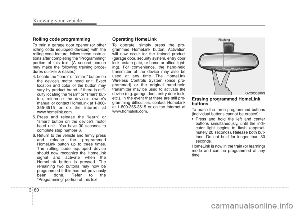
Erasing programmed HomeLink
buttons
To erase the three programmed buttons
(individual buttons cannot be erased):
• Press and hold the left and center
buttons simultaneously, until the indi-
cator light begins to flash (approxi-
mately 20 seconds). Release both but-
tons. Do not hold for longer than 30
seconds.
HomeLink is now in the train (or learning)
mode and can be programmed at any
time.
OVQ036306N Flashing
Page 118 of 326
3 109
Knowing your vehicle
1. SCAN button
Frequency band scan function
Press the SCANbutton for the tuner to
scan for radio signals in the selected fre-
quency band (AM or FM). Once the tuner
locks onto the signal of a transmitting
station, it plays that station for 5 seconds
before scanning for the next available
station in the selected frequency band.
If you want to keep listening to a particu-
lar station and want to stop the scanning,
press the SCANbutton again.
This function is useful for providing you
with a good overview of all the radio sta-
tions within range of your tuner.
2. PRESET SCAN function
Press and hold the SCANbutton for
more than 2 seconds. Each preset radio
stations will be automatically played for 5
seconds. If you want to keep listening to
a particular preset station and want to
stop the scanning, press the SCANbut-
ton again.
3. SEEK and buttons
Automatic Channel Selection function
Press the and buttons to scan up
and down the frequency range for the
next available radio station and automat-
ically lock on to that frequency.
The LCD screen displays the frequency
of the radio station transmitting a clear
and strong signal.
Use this function to search for a radio
station you want. If you like a particular
station, you can store it as one of 6
Presets using the Presetbuttons below.
✽
NOTICE
This function is not effective if you are
experiencing poor reception in your
vicinity.
4. Tuning Knob
Manual Channel Selection
Rotate the knob clockwise or counter-
clockwise to manually advance up or
down the frequency range. The tuning
knob also gives you fine-grain control
which you can use to manually fine-tune
your frequency selection. This is useful if
you are searching for a radio signal
which is not strong enough for you to use
the Automatic Channel Selection func-
tion
✽
NOTICE
The speed at which you advance up or
down the frequency range depends on
how fast you turn the knob.
Page 166 of 326
Driving your vehicle
36 4
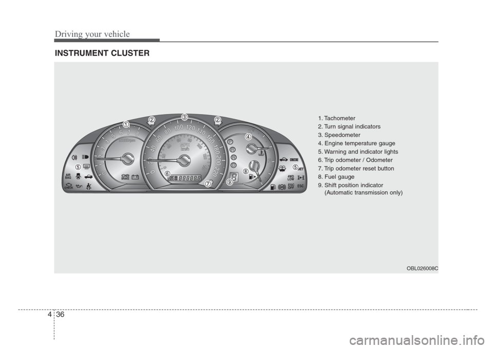
INSTRUMENT CLUSTER
ESCESC
1. Tachometer
2. Turn signal indicators
3. Speedometer
4. Engine temperature gauge
5. Warning and indicator lights
6. Trip odometer / Odometer
7. Trip odometer reset button
8. Fuel gauge
9. Shift position indicator
(Automatic transmission only)
OBL026008C
Page 172 of 326
Driving your vehicle
42 4
Door ajar warning
This warning light illuminates when a
door is not closed securely with the igni-
tion in any position.
Headlight high beam
indicator
This indicator illuminates when the head-
lights are on and in the high beam posi-
tion or when the turn signal lever is pulled
into the Flash-to-Pass position.
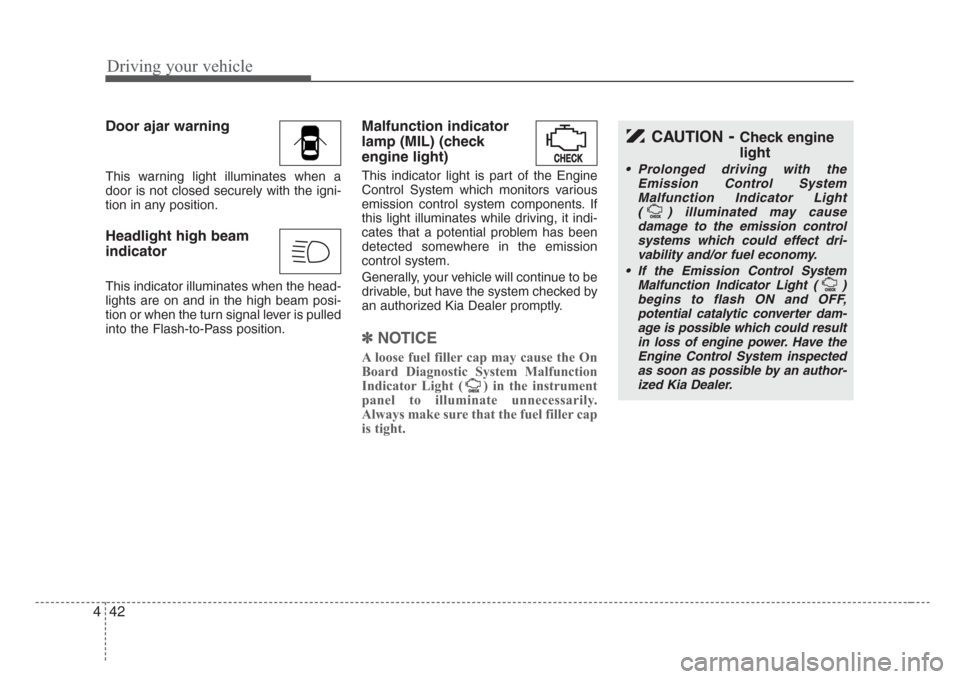
Malfunction indicator
lamp (MIL) (check
engine light)
This indicator light is part of the Engine
Control System which monitors various
emission control system components. If
this light illuminates while driving, it indi-
cates that a potential problem has been
detected somewhere in the emission
control system.
Generally, your vehicle will continue to be
drivable, but have the system checked by
an authorized Kia Dealer promptly.
✽
NOTICE
A loose fuel filler cap may cause the On
Board Diagnostic System Malfunction
Indicator Light ( ) in the instrument
panel to illuminate unnecessarily.
Always make sure that the fuel filler cap
is tight.
CAUTION-Check engine
light
• Prolonged driving with the
Emission Control System
Malfunction Indicator Light
( ) illuminated may cause
damage to the emission control
systems which could effect dri-
vability and/or fuel economy.
•
If the EmissionControl System
Malfunction Indicator Light ( )
begins to flash ON and OFF,
potential catalytic converter dam-
age is possible which could result
in loss of engine power. Have the
Engine Control System inspected
as soon as possible by an author-
ized Kia Dealer.
Page 182 of 326
Driving your vehicle
52 4
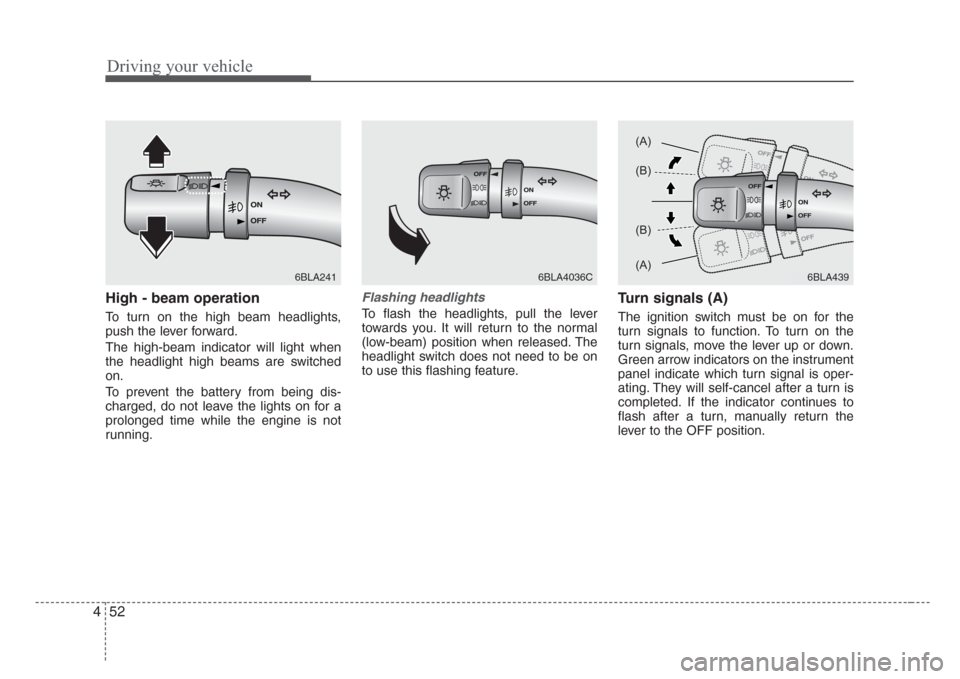
High - beam operation
To turn on the high beam headlights,
push the lever forward.
The high-beam indicator will light when
the headlight high beams are switched
on.
To prevent the battery from being dis-
charged, do not leave the lights on for a
prolonged time while the engine is not
running.
Flashing headlights
To flash the headlights, pull the lever
towards you. It will return to the normal
(low-beam) position when released. The
headlight switch does not need to be on
to use this flashing feature.
Turn signals (A)
The ignition switch must be on for the
turn signals to function. To turn on the
turn signals, move the lever up or down.
Green arrow indicators on the instrument
panel indicate which turn signal is oper-
ating. They will self-cancel after a turn is
completed. If the indicator continues to
flash after a turn, manually return the
lever to the OFF position.
6BLA2416BLA4036C6BLA439
(A)
(B)
(B)
(A)
Page 183 of 326
453
Driving your vehicle
Lane change signals (B)
To signal a lane change, move the turn
signal lever slightly and hold it in position.
The lever will return to the OFF position
when released.
If an indicator stays on and does not
flash or if it flashes abnormally, one of the
turn signal bulbs may be burned out and
will require replacement.
✽
NOTICE
If an indicator flash is abnormally quick
or slow, bulb may be burned out or have
a poor electrical connection in the cir-
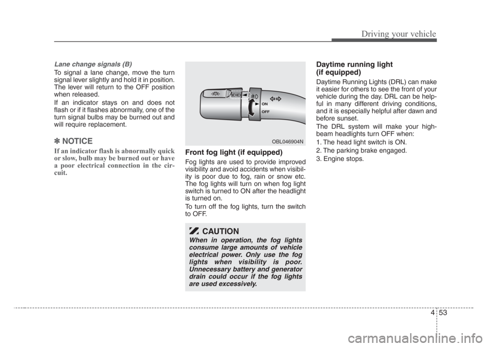
cuit.Front fog light (if equipped)
Fog lights are used to provide improved
visibility and avoid accidents when visibil-
ity is poor due to fog, rain or snow etc.
The fog lights will turn on when fog light
switch is turned to ON after the headlight
is turned on.
To turn off the fog lights, turn the switch
to OFF.
Daytime running light
(if equipped)
Daytime Running Lights (DRL) can make
it easier for others to see the front of your
vehicle during the day. DRL can be help-
ful in many different driving conditions,
and it is especially helpful after dawn and
before sunset.
The DRL system will make your high-
beam headlights turn OFF when:
1. The head light switch is ON.
2. The parking brake engaged.
3. Engine stops.
OBL046904N
CAUTION
When in operation, the fog lights
consume large amounts of vehicle
electrical power. Only use the fog
lights when visibility is poor.
Unnecessary battery and generator
drain could occur if the fog lights
are used excessively.