battery terminal KIA SORENTO 2018 Owners Manual
[x] Cancel search | Manufacturer: KIA, Model Year: 2018, Model line: SORENTO, Model: KIA SORENTO 2018Pages: 536, PDF Size: 13.42 MB
Page 15 of 536
Your vehicle at a glance
62
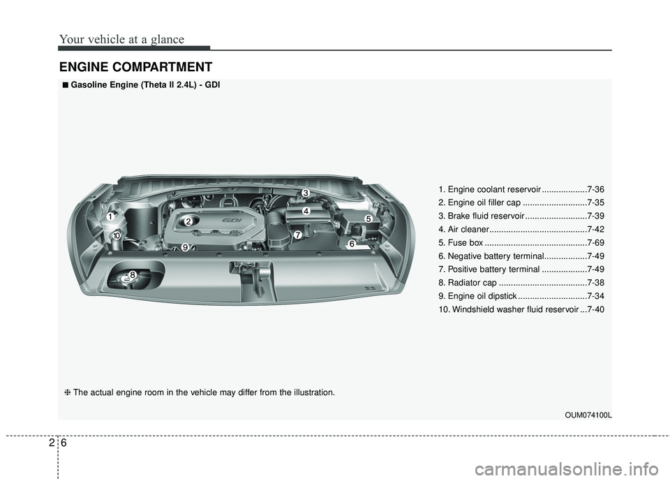
ENGINE COMPARTMENT
OUM074100L
■ ■Gasoline Engine (Theta II 2.4L) - GDI
❈ The actual engine room in the vehicle may differ from the illustration. 1. Engine coolant reservoir ...................7-36
2. Engine oil filler cap ...........................7-35
3. Brake fluid reservoir ..........................7-39
4. Air cleaner.........................................7-42
5. Fuse box ...........................................7-69
6. Negative battery terminal..................7-49
7. Positive battery terminal ...................7-49
8. Radiator cap .....................................7-38
9. Engine oil dipstick .............................7-34
10. Windshield washer fluid reservoir ...7-40
Page 16 of 536
27
Your vehicle at a glance
OUM074115L
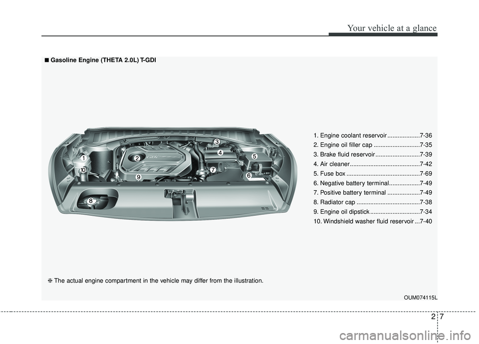
■ ■Gasoline Engine (THETA 2.0L) T-GDI
❈ The actual engine compartment in the vehicle may differ from the illustration. 1. Engine coolant reservoir ...................7-36
2. Engine oil filler cap ...........................7-35
3. Brake fluid reservoir ..........................7-39
4. Air cleaner.........................................7-42
5. Fuse box ...........................................7-69
6. Negative battery terminal..................7-49
7. Positive battery terminal ...................7-49
8. Radiator cap .....................................7-38
9. Engine oil dipstick .............................7-34
10. Windshield washer fluid reservoir ...7-40
Page 17 of 536
Your vehicle at a glance
82
OUMA074001
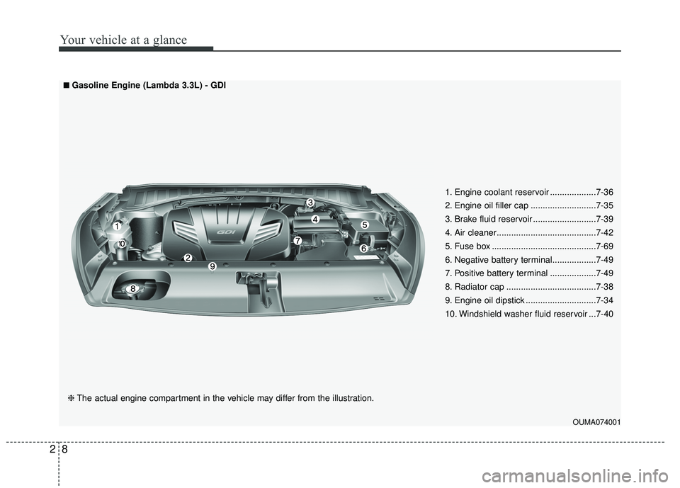
■ ■Gasoline Engine (Lambda 3.3L) - GDI
❈ The actual engine compartment in the vehicle may differ from the illustration. 1. Engine coolant reservoir ...................7-36
2. Engine oil filler cap ...........................7-35
3. Brake fluid reservoir ..........................7-39
4. Air cleaner.........................................7-42
5. Fuse box ...........................................7-69
6. Negative battery terminal..................7-49
7. Positive battery terminal ...................7-49
8. Radiator cap .....................................7-38
9. Engine oil dipstick .............................7-34
10. Windshield washer fluid reservoir ...7-40
Page 68 of 536
351
Safety features of your vehicle
The SRS can function only whenthe ignition switch is in the ON
position. If the SRS air bag warning
light does not illuminate, or contin-
uously remains on after illuminat-
ing for about 6 seconds when the
ignition switch is turned to the ON
position, or after the engine is
started, comes on while driving,
the SRS is not working properly. If
this occurs, have your vehicle
immediately inspected by an
authorized Kia dealer.
✽ ✽ NOTICE
Before you replace a fuse or discon-
nect a battery terminal, turn the
ignition switch to the LOCK posi-
tion and remove the ignition switch.
Never remove or replace the air bag
related fuse(s) when the ignition
switch is in the ON position. Failure
to heed this warning will cause the
SRS air bag warning light to illumi-
nate.
Occupant Detection System
(ODS)
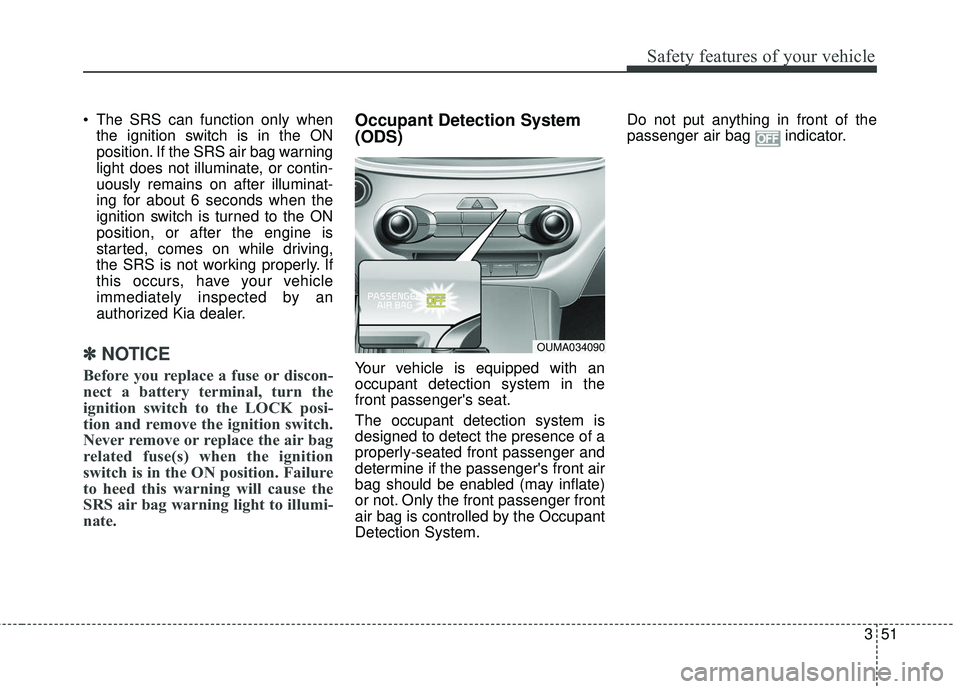
Your vehicle is equipped with an
occupant detection system in the
front passenger's seat.
The occupant detection system is
designed to detect the presence of a
properly-seated front passenger and
determine if the passenger's front air
bag should be enabled (may inflate)
or not. Only the front passenger front
air bag is controlled by the Occupant
Detection System. Do not put anything in front of the
passenger air bag indicator.
OUMA034090
Page 267 of 536
Features of your vehicle
182
4
(Continued)
If you use devices such as a USB
hub purchased separately, the
vehicle’s audio system may not
recognize the USB device. In that
case, connect the USB device
directly to the multimedia terminal
of the vehicle.
If the USB device is divided by log- ical drives, only the music files on
the highest-priority drive are recog-
nized by car audio.
Devices such as MP3 Player/ Cellular phone/Digital camera can
be unrecognizable by standard
USB I/F can be unrecognizable.
Charging through the USB may not be supported in some mobile
devices.
USB HDD or USB types liable to connection failures due to vehicle
vibrations are not supported. (i-stick
type)
Some non-standard USB devices (METAL COVER TYPE USB) can
be unrecognizable.
(Continued)(Continued)
Some USB flash memory readers
(such as CF, SD, micro SD, etc.) or
external-HDD type devices can be
unrecognizable.
Music files protected by DRM (DIGI- TAL RIGHTS MANAGEMENT) are
not recognizable.
The data in the USB memory may be lost while using this audio.
Always back up important data on
a personal storage device.
Please avoid using USB memory products
which can be used as
key chains or cellular
phone accessories as they could
cause damage to the USB jack.
Please make certain only to use
plug type connector products.USING iPod®DEVICE
iPhone®is a registered trademark of
Apple inc.
Some iPod
®models may not sup-
port communication protocol and
files may not play properly.
Supported iPod
®models:
- iPhone
®3GS/4 or latest model
- iPod
®touch 1st~4th generation
- iPod
®nano 1st~6th generation
- iPod
®classic
The order of search or playback of songs in the iPod
®can be different
from the order searched in the
audio system.
If the iPod
®is disabled due to its
own malfunction, reset the iPod®.
(Reset: Refer to iPod®manual)
An iPod
®may not operate normally
on low battery.
(Continued)
Page 398 of 536
What to do in an emergency
66
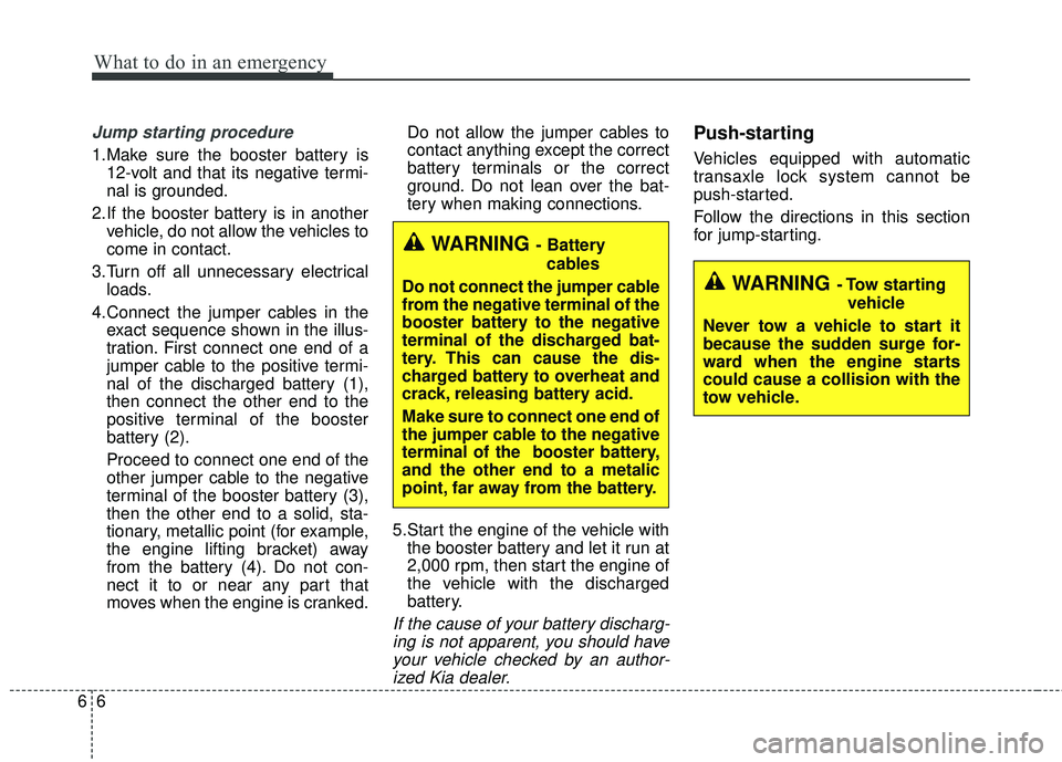
Jump starting procedure
1.Make sure the booster battery is12-volt and that its negative termi-
nal is grounded.
2.If the booster battery is in another vehicle, do not allow the vehicles to
come in contact.
3.Turn off all unnecessary electrical loads.
4.Connect the jumper cables in the exact sequence shown in the illus-
tration. First connect one end of a
jumper cable to the positive termi-
nal of the discharged battery (1),
then connect the other end to the
positive terminal of the booster
battery (2).
Proceed to connect one end of the
other jumper cable to the negative
terminal of the booster battery (3),
then the other end to a solid, sta-
tionary, metallic point (for example,
the engine lifting bracket) away
from the battery (4). Do not con-
nect it to or near any part that
moves when the engine is cranked. Do not allow the jumper cables to
contact anything except the correct
battery terminals or the correct
ground. Do not lean over the bat-
tery when making connections.
5.Start the engine of the vehicle with the booster battery and let it run at
2,000 rpm, then start the engine of
the vehicle with the discharged
battery.
If the cause of your battery discharg-ing is not apparent, you should haveyour vehicle checked by an author-ized Kia dealer.
Push-starting
Vehicles equipped with automatic
transaxle lock system cannot be
push-started.
Follow the directions in this section
for jump-starting.
WARNING - Tow starting
vehicle
Never tow a vehicle to start it
because the sudden surge for-
ward when the engine starts
could cause a collision with the
tow vehicle.
WARNING - Battery cables
Do not connect the jumper cable
from the negative terminal of the
booster battery to the negative
terminal of the discharged bat-
tery. This can cause the dis-
charged battery to overheat and
crack, releasing battery acid.
Make sure to connect one end of
the jumper cable to the negative
terminal of the booster battery,
and the other end to a metalic
point, far away from the battery.
Page 414 of 536
73
Maintenance
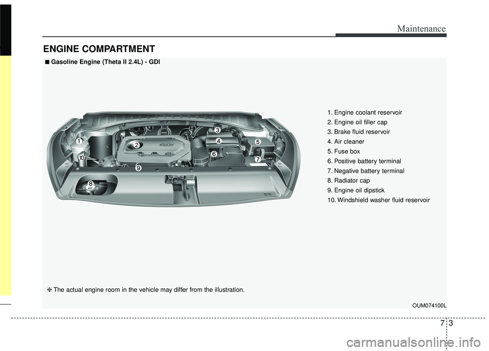
ENGINE COMPARTMENT
OUM074100L
■ ■Gasoline Engine (Theta II 2.4L) - GDI
❈The actual engine room in the vehicle may differ from the illustration. 1. Engine coolant reservoir
2. Engine oil filler cap
3. Brake fluid reservoir
4. Air cleaner
5. Fuse box
6. Positive battery terminal
7. Negative battery terminal
8. Radiator cap
9. Engine oil dipstick
10. Windshield washer fluid reservoir
Page 415 of 536
Maintenance
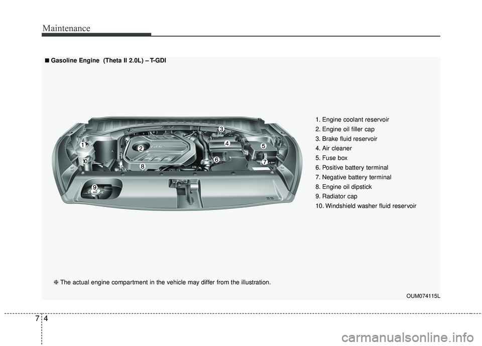
47
OUM074115L
■ ■Gasoline Engine (Theta II 2.0L) – T-GDI❈ The actual engine compartment in the vehicle may differ from the illustration. 1. Engine coolant reservoir
2. Engine oil filler cap
3. Brake fluid reservoir
4. Air cleaner
5. Fuse box
6. Positive battery terminal
7. Negative battery terminal
8. Engine oil dipstick
9. Radiator cap
10. Windshield washer fluid reservoir
Page 416 of 536
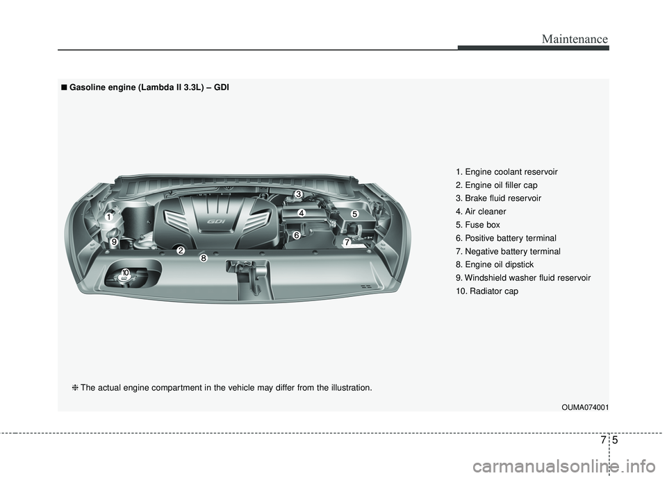
75
Maintenance
OUMA074001
1. Engine coolant reservoir
2. Engine oil filler cap
3. Brake fluid reservoir
4. Air cleaner
5. Fuse box
6. Positive battery terminal
7. Negative battery terminal
8. Engine oil dipstick
9. Windshield washer fluid reservoir
10. Radiator cap
■ ■Gasoline engine (Lambda II 3.3L) – GDI❈ The actual engine compartment in the vehicle may differ from the illustration.
Page 420 of 536
79
Maintenance
At least monthly:
Check the coolant level in theengine coolant reservoir.
Check the operation of all exterior lights, including the stoplights, turn
signals and hazard warning flash-
ers.
Check the inflation pressures of all tires including the spare.
At least twice a year
(i.e., every Spring and Fall):
Check the radiator, heater and air conditioning hoses for leaks or
damage.
Check the windshield washer spray and wiper operation. Clean
the wiper blades with clean cloth
dampened with washer fluid.
Check the headlight alignment.
Check the muffler, exhaust pipes, shields and clamps.
Check the lap/shoulder belts for wear and function.
Check for worn tires and loose wheel lug nuts.
At least once a year:
Clean the body and door drainholes.
Lubricate the door hinges and checks, and hood hinges.
Lubricate the door and hood locks and latches.
Lubricate the door rubber weather- strips.
Check the air conditioning system.
Inspect and lubricate the automat- ic transaxle linkage and controls.
Clean the battery and terminals.
Check the brake fluid level.