instrument panel KIA SOUL EV 2018 User Guide
[x] Cancel search | Manufacturer: KIA, Model Year: 2018, Model line: SOUL EV, Model: KIA SOUL EV 2018Pages: 496, PDF Size: 15.13 MB
Page 122 of 496
349
Safety features of your vehicle
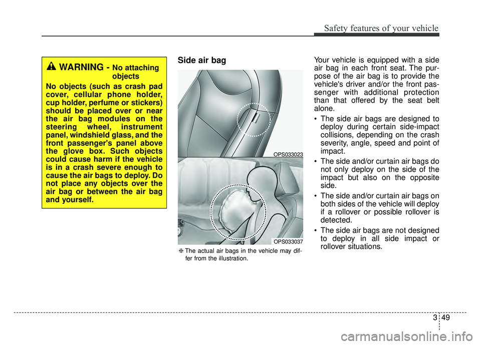
Side air bagYour vehicle is equipped with a side
air bag in each front seat. The pur-
pose of the air bag is to provide the
vehicle's driver and/or the front pas-
senger with additional protection
than that offered by the seat belt
alone.
The side air bags are designed todeploy during certain side-impact
collisions, depending on the crash
severity, angle, speed and point of
impact.
The side and/or curtain air bags do not only deploy on the side of the
impact but also on the opposite
side.
The side and/or curtain air bags on both sides of the vehicle will deploy
if a rollover or possible rollover is
detected.
The side air bags are not designed to deploy in all side impact or
rollover situations.
WARNING - No attaching
objects
No objects (such as crash pad
cover, cellular phone holder,
cup holder, perfume or stickers)
should be placed over or near
the air bag modules on the
steering wheel, instrument
panel, windshield glass, and the
front passenger's panel above
the glove box. Such objects
could cause harm if the vehicle
is in a crash severe enough to
cause the air bags to deploy. Do
not place any objects over the
air bag or between the air bag
and yourself.
OPS033037
OPS033023
❈ The actual air bags in the vehicle may dif-
fer from the illustration.
Page 162 of 496
431
Features of your vehicle
(Continued)
• When you operate the steeringwheel in low temperature, abnor-
mal noise may occur. If tempera-
ture rises, the noise will likely dis-
appear. This is a normal condition.
• When the charging system warn- ing light comes on due to the low
voltage (When the alternator or
battery) does not operate normal-
ly or it malfunctions), the steering
wheel may require increased
steering effort.Tilt and telescopic steering
Tilt and telescopic steering allows
you to adjust the steering wheel
before you drive. You can also raise it
to give your legs more room when
you exit and enter the vehicle.
The steering wheel should be posi-
tioned so that it is comfortable for
you to drive, while permitting you to
see the instrument panel warning
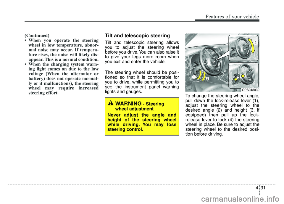
lights and gauges. To change the steering wheel angle,
pull down the lock-release lever (1),
adjust the steering wheel to the
desired angle (2) and height (3, if
equipped) then pull up the lock-
release lever to lock (4) the steering
wheel in place. Be sure to adjust the
steering wheel to the desired posi-
tion before driving.
OPS043032
WARNING- Steering
wheel adjustment
Never adjust the angle and
height of the steering wheel
while driving. You may lose
steering control.
Page 172 of 496
441
Features of your vehicle
Instrument Cluster Control
Adjusting Instrument ClusterIllumination
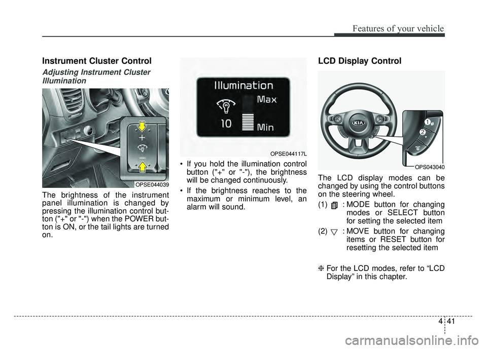
The brightness of the instrument
panel illumination is changed by
pressing the illumination control but-
ton ("+" or "-") when the POWER but-
ton is ON, or the tail lights are turned
on. If you hold the illumination control
button ("+" or "-"), the brightness
will be changed continuously.
If the brightness reaches to the maximum or minimum level, an
alarm will sound.
LCD Display Control
The LCD display modes can be
changed by using the control buttons
on the steering wheel.
(1) : MODE button for changing modes or SELECT button
for setting the selected item
(2) : MOVE button for changing items or RESET button for
resetting the selected item
❈ For the LCD modes, refer to “LCD
Display” in this chapter.OPSE044039
OPSE044117L
OPS043040
Page 214 of 496
483
Features of your vehicle
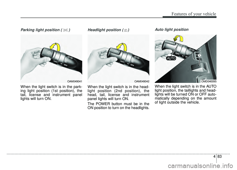
Parking light position ( )
When the light switch is in the park-
ing light position (1st position), the
tail, license and instrument panel
lights will turn ON.
Headlight position ( )
When the light switch is in the head-
light position (2nd position), the
head, tail, license and instrument
panel lights will turn ON.
The POWER button must be in the
ON position to turn on the headlights.
Auto light position
When the light switch is in the AUTO
light position, the taillights and head-
lights will be turned ON or OFF auto-
matically depending on the amount
of light outside the vehicle.
OAM049041OAM049042OMD040095
Page 215 of 496
Features of your vehicle
84
4
Never place anything over sensor
(1) located on the instrument
panel. This will ensure better auto-
light system control.
Don’t clean the sensor using a win- dow cleaner. The cleaner may
leave a light film which could inter-
fere with sensor operation.
If your vehicle has window tint or other types of metallic coating on
the front windshield, the Auto light
system may not work properly.High beam operation
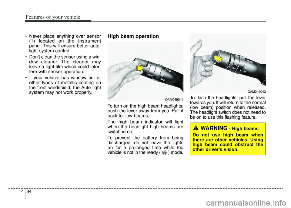
To turn on the high beam headlights,
push the lever away from you. Pull it
back for low beams.
The high beam indicator will light
when the headlight high beams are
switched on.
To prevent the battery from being
discharged, do not leave the lights
on for a prolonged time while the
vehicle is not in the ready ( ) mode. To flash the headlights, pull the lever
towards you. It will return to the normal
(low beam) position when released.
The headlight switch does not need to
be on to use this flashing feature.
OAM049044
OAM049043
WARNING- High beams
Do not use high beam when
there are other vehicles. Using
high beam could obstruct the
other driver's vision.
Page 216 of 496
485
Features of your vehicle
Turn signals and lane change
signals
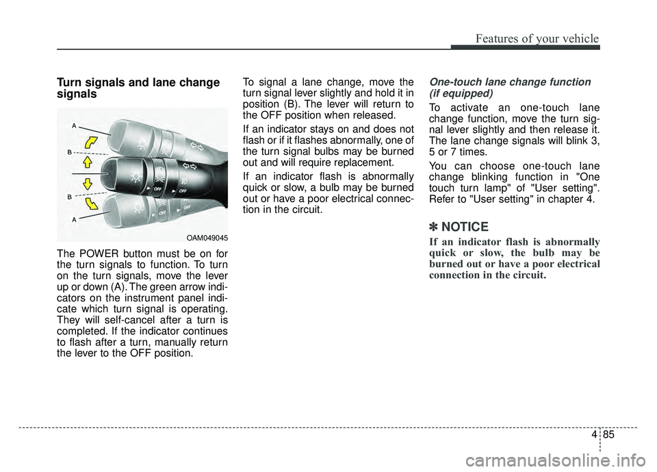
The POWER button must be on for
the turn signals to function. To turn
on the turn signals, move the lever
up or down (A). The green arrow indi-
cators on the instrument panel indi-
cate which turn signal is operating.
They will self-cancel after a turn is
completed. If the indicator continues
to flash after a turn, manually return
the lever to the OFF position.To signal a lane change, move the
turn signal lever slightly and hold it in
position (B). The lever will return to
the OFF position when released.
If an indicator stays on and does not
flash or if it flashes abnormally, one of
the turn signal bulbs may be burned
out and will require replacement.
If an indicator flash is abnormally
quick or slow, a bulb may be burned
out or have a poor electrical connec-
tion in the circuit.
One-touch lane change function
(if equipped)
To activate an one-touch lane
change function, move the turn sig-
nal lever slightly and then release it.
The lane change signals will blink 3,
5 or 7 times.
You can choose one-touch lane
change blinking function in "One
touch turn lamp" of "User setting".
Refer to "User setting" in chapter 4.
✽ ✽ NOTICE
If an indicator flash is abnormally
quick or slow, the bulb may be
burned out or have a poor electrical
connection in the circuit.OAM049045
Page 224 of 496
493
Features of your vehicle
✽
✽NOTICE
If you want to defrost and defog the
front windshield, refer to
“Windshield defrosting and defog-
ging” in this section.
Rear window defroster
The defroster heats the window to
remove frost, fog and thin ice from
the rear window, while the v ehicle is
in the ready ( ) mode. To activate the rear window
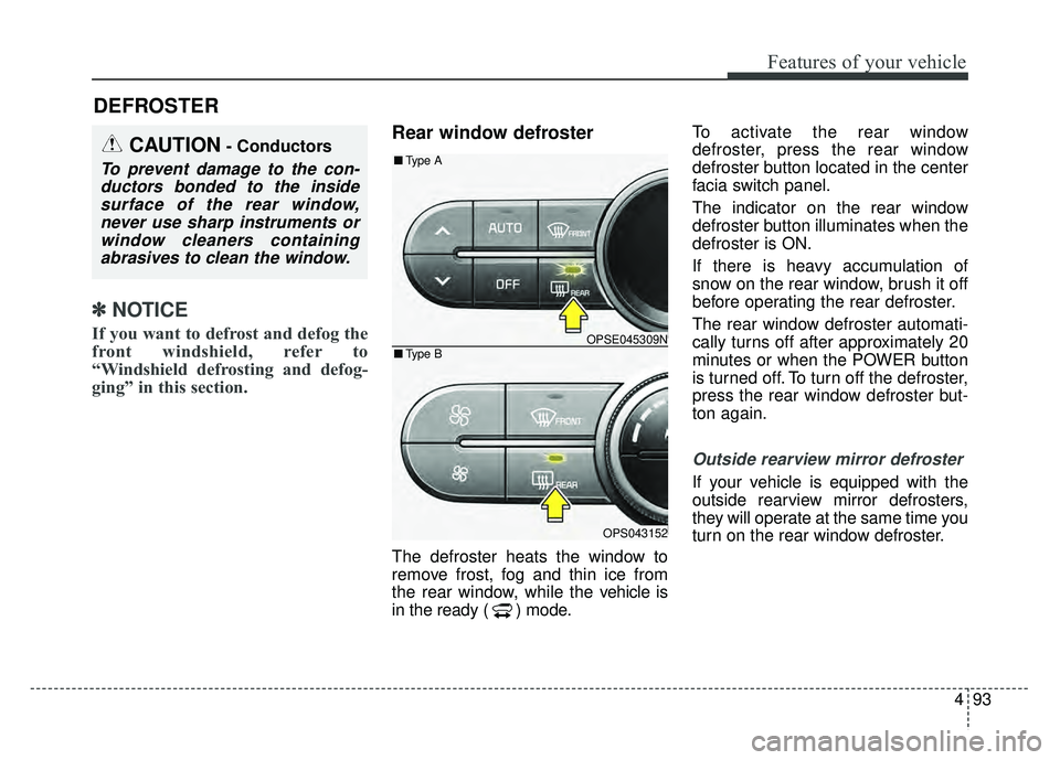
defroster, press the rear window
defroster button located in the center
facia switch panel.
The indicator on the rear window
defroster button illuminates when the
defroster is ON.
If there is heavy accumulation of
snow on the rear window, brush it off
before operating the rear defroster.
The rear window defroster automati-
cally turns off after approximately 20
minutes or when the POWER button
is turned off. To turn off the defroster,
press the rear window defroster but-
ton again.
Outside rearview mirror defroster
If your vehicle is equipped with the
outside rearview mirror defrosters,
they will operate at the same time you
turn on the rear window defroster.
DEFROSTER
CAUTION- Conductors
To prevent damage to the con-
ductors bonded to the insidesurface of the rear window,never use sharp instruments orwindow cleaners containingabrasives to clean the window.
OPSE045309N
OPS043152
■ Type B
■Type A
Page 227 of 496
Features of your vehicle
96
4
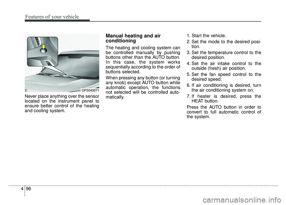
Never place anything over the sensor
located on the instrument panel to
ensure better control of the heating
and cooling system.
Manual heating and air
conditioning
The heating and cooling system can
be controlled manually by pushing
buttons other than the AUTO button.
In this case, the system works
sequentially according to the order of
buttons selected.
When pressing any button (or turning
any knob) except AUTO button while
automatic operation, the functions
not selected will be controlled auto-
matically. 1. Start the vehicle.
2. Set the mode to the desired posi-
tion.
3. Set the temperature control to the desired position.
4. Set the air intake control to the outside (fresh) air position.
5. Set the fan speed control to the desired speed.
6. If air conditioning is desired, turn the air conditioning system on.
7. If heater is desired, press the HEAT button.
Press the AUTO button in order to
convert to full automatic control of
the system.
OPS043071
Page 230 of 496
499
Features of your vehicle
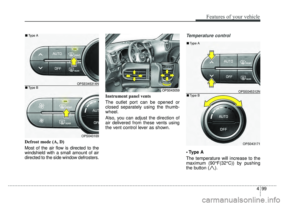
Defrost mode (A, D)
Most of the air flow is directed to the
windshield with a small amount of air
directed to the side window defrosters.Instrument panel vents
The outlet port can be opened or
closed separately using the thumb-
wheel.
Also, you can adjust the direction of
air delivered from these vents using
the vent control lever as shown.
Temperature control
A
The temperature will increase to the
maximum (90°F(32°C)) by pushing
the button ( ).
OPS043059
OPSE045314N
OPS043169
■
Type B
■Type A
OPSE045312N
OPS043171
■Type B
■Type A
Page 447 of 496
757
Maintenance
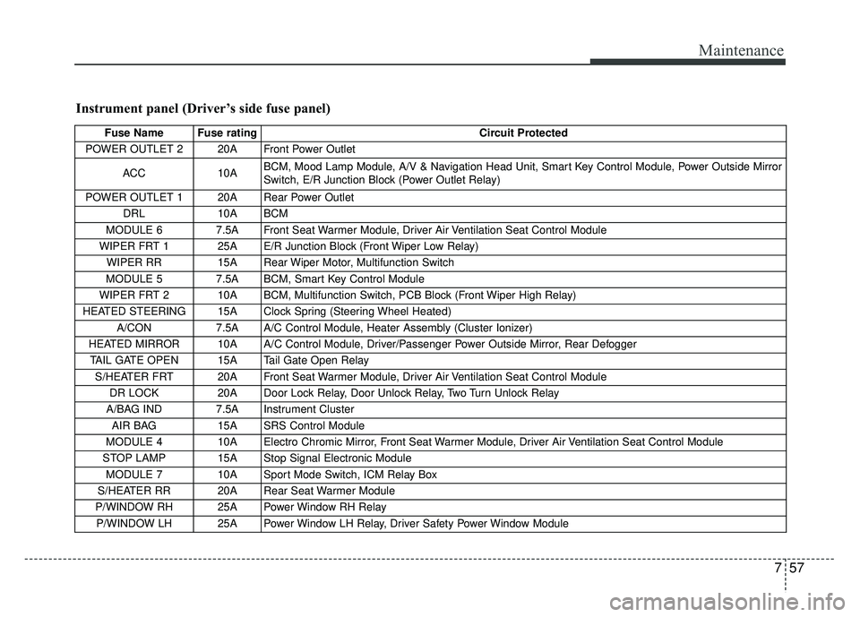
Instrument panel (Driver’s side fuse panel)
Fuse Name Fuse ratingCircuit Protected
POWER OUTLET 2 20A Front Power Outlet
ACC 10A BCM, Mood Lamp Module, A/V & Navigation Head Unit, Smart Key Control Module, Power Outside Mirror
Switch, E/R Junction Block (Power Outlet Relay)
POWER OUTLET 1 20A Rear Power Outlet DRL 10A BCM
MODULE 6 7.5A Front Seat Warmer Module, Driver Air Ventilation Seat Control Module
WIPER FRT 1 25A E/R Junction Block (Front Wiper Low Relay) WIPER RR 15A Rear Wiper Motor, Multifunction Switch
MODULE 5 7.5A BCM, Smart Key Control Module
WIPER FRT 2 10A BCM, Multifunction Switch, PCB Block (Front Wiper High Relay)
HEATED STEERING 15A Clock Spring (Steering Wheel Heated) A/CON 7.5A A/C Control Module, Heater Assembly (Cluster Ionizer)
HEATED MIRROR 10A A/C Control Module, Driver/Passenger Power Outside Mirror, Rear Defogger TAIL GATE OPEN 15A Tail Gate Open Relay S/HEATER FRT 20A Front Seat Warmer Module, Driver Air Ventilation Seat Control Module DR LOCK 20A Door Lock Relay, Door Unlock Relay, Two Turn Unlock Relay
A/BAG IND 7.5A Instrument Cluster AIR BAG 15A SRS Control Module
MODULE 4 10A Electro Chromic Mirror, Front Seat Warmer Module, Driver Air Ventilation Seat Control Module
STOP LAMP 15A Stop Signal Electronic Module MODULE 7 10A Sport Mode Switch, ICM Relay Box
S/HEATER RR 20A Rear Seat Warmer Module
P/WINDOW RH 25A Power Window RH Relay P/WINDOW LH 25A Power Window LH Relay, Driver Safety Power Window Module