oil KIA Sportage 2013 SL / 3.G Owner's Guide
[x] Cancel search | Manufacturer: KIA, Model Year: 2013, Model line: Sportage, Model: KIA Sportage 2013 SL / 3.GPages: 387, PDF Size: 8.44 MB
Page 329 of 387
711
Maintenance
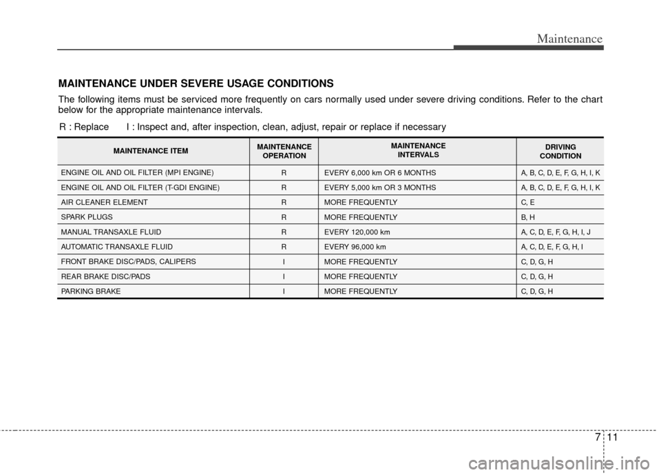
MAINTENANCE UNDER SEVERE USAGE CONDITIONS
The following items must be serviced more frequently on cars normally used under severe driving conditions. Refer to the chart
below for the appropriate maintenance intervals.R : Replace I : Inspect and, after inspection, clean, adjust, repair or replace if neces\
sary
R
R
R
R
R
R
I
I
I EVERY 6,000 km OR 6 MONTHS
EVERY 5,000 km OR 3 MONTHS
MORE FREQUENTLY
MORE FREQUENTLY
EVERY 120,000 km
EVERY 96,000 km
MORE FREQUENTLY
MORE FREQUENTLY
MORE FREQUENTLYA, B, C, D, E, F, G, H, I, K
A, B, C, D, E, F, G, H, I, K
C, E
B, H
A, C, D, E, F, G, H, I, J
A, C, D, E, F, G, H, I
C, D, G, H
C, D, G, H
C, D, G, H ENGINE OIL AND OIL FILTER (MPI ENGINE)
ENGINE OIL AND OIL FILTER (T-GDI ENGINE)
AIR CLEANER ELEMENT
SPARK PLUGS
MANUAL TRANSAXLE FLUID
AUTOMATIC TRANSAXLE FLUID
FRONT BRAKE DISC/PADS, CALIPERS
REAR BRAKE DISC/PADS
PARKING BRAKE
MAINTENANCE ITEM
MAINTENANCE
OPERATION MAINTENANCE
INTERVALS DRIVING
CONDITION
Page 330 of 387
Maintenance
12
7
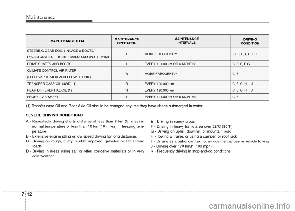
SEVERE DRIVING CONDITIONS
A - Repeatedly driving shorts distanse of less than 8 km (5 miles) in
normal temperature or less than 16 km (10 miles) in freezing tem-
perature
B - Extensive engine idling or low speed driving for long distances
C - Driving on rough, dusty, muddy, unpaved, graveled or salt-spread roads
D - Driving in areas using salt or other corrosive materials or in very cold weather E - Driving in sandy areas
F - Driving in heavy traffic area over 32°C (90°F)
G - Driving on uphill, downhill, or mountain road
H - Towing a Trailer, or using a camper, or roof rack
I - Driving as a patrol car, taxi, other commercial use or vehicle towing
J - Driving over 170 km/h (100 mph)
K - Frequently driving in stop-and-go conditions
I
I
R
R
R I MORE FREQUENTLY
EVERY 12,000 km OR 6 MONTHS
MORE FREQUENTLY
EVERY 120,000 km
EVERY 120,000 km
EVERY 12,000 km OR 6 MONTHSC, D, E, F, G, H, I
C, D, E, F, G
C, E
C, E, G, H, I, J
C, E, G, H, I, J
C, ESTEERING GEAR BOX, LINKAGE & BOOTS/
LOWER ARM BALL JOINT, UPPER ARM BSALL JOINT
DRIVE SHAFTS AND BOOTS
CLIMATE CONTROL AIR FILTER
(FOR EVAPORATOR AND BLOWER UNIT)
TRANSFER CASE OIL (4WD) (1)
REAR DIFFERENTIAL OIL (1)
PROPELLAR SHAFT
MAINTENANCE ITEM MAINTENANCE
OPERATION MAINTENANCE
INTERVALS DRIVING
CONDITION
(1) Transfer case Oil and Rear Axle Oil should be changed anytime they have abeen submerged in water.
Page 331 of 387
713
Maintenance
EXPLANATION OF SCHEDULED MAINTENANCE ITEMS
G050100AHM
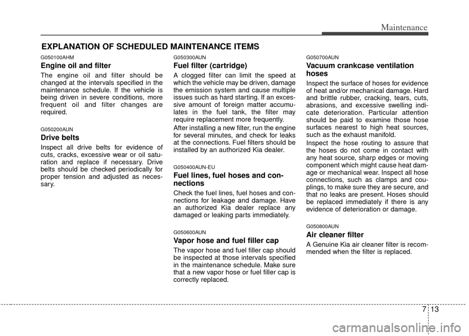
Engine oil and filter
The engine oil and filter should be
changed at the intervals specified in the
maintenance schedule. If the vehicle is
being driven in severe conditions, more
frequent oil and filter changes are
required.
G050200AUN
Drive belts
Inspect all drive belts for evidence of
cuts, cracks, excessive wear or oil satu-
ration and replace if necessary. Drive
belts should be checked periodically for
proper tension and adjusted as neces-
sary.
G050300AUN
Fuel filter (cartridge)
A clogged filter can limit the speed at
which the vehicle may be driven, damage
the emission system and cause multiple
issues such as hard starting. If an exces-
sive amount of foreign matter accumu-
lates in the fuel tank, the filter may
require replacement more frequently.
After installing a new filter, run the engine
for several minutes, and check for leaks
at the connections. Fuel filters should be
installed by an authorized Kia dealer.
G050400AUN-EU
Fuel lines, fuel hoses and con-
nections
Check the fuel lines, fuel hoses and con-
nections for leakage and damage. Have
an authorized Kia dealer replace any
damaged or leaking parts immediately.
G050600AUN
Vapor hose and fuel filler cap
The vapor hose and fuel filler cap should
be inspected at those intervals specified
in the maintenance schedule. Make sure
that a new vapor hose or fuel filler cap is
correctly replaced.
G050700AUN
Vacuum crankcase ventilation
hoses
Inspect the surface of hoses for evidence
of heat and/or mechanical damage. Hard
and brittle rubber, cracking, tears, cuts,
abrasions, and excessive swelling indi-
cate deterioration. Particular attention
should be paid to examine those hose
surfaces nearest to high heat sources,
such as the exhaust manifold.
Inspect the hose routing to assure that
the hoses do not come in contact with
any heat source, sharp edges or moving
component which might cause heat dam-
age or mechanical wear. Inspect all hose
connections, such as clamps and cou-
plings, to make sure they are secure, and
that no leaks are present. Hoses should
be replaced immediately if there is any
evidence of deterioration or damage.
G050800AUN
Air cleaner filter
A Genuine Kia air cleaner filter is recom-
mended when the filter is replaced.
Page 334 of 387
Maintenance
16
7
ENGINE OIL
❈ The actual feature may differ from the illus-
tration.
G060100AHM-EU
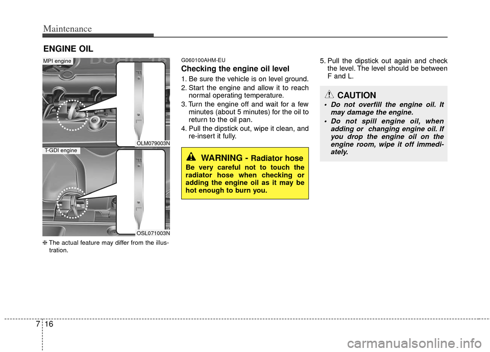
Checking the engine oil level
1. Be sure the vehicle is on level ground.
2. Start the engine and allow it to reach normal operating temperature.
3. Turn the engine off and wait for a few minutes (about 5 minutes) for the oil to
return to the oil pan.
4. Pull the dipstick out, wipe it clean, and re-insert it fully. 5. Pull the dipstick out again and check
the level. The level should be between
F and L.
WARNING - Radiator hose
Be very careful not to touch the
radiator hose when checking or
adding the engine oil as it may be
hot enough to burn you.
CAUTION
Do not overfill the engine oil. It may damage the engine.
Do not spill engine oil, when adding or changing engine oil. Ifyou drop the engine oil on theengine room, wipe it off immedi-ately.
OLM079003N
OSL071003N
MPI engine
T-GDI engine
Page 335 of 387
717
Maintenance
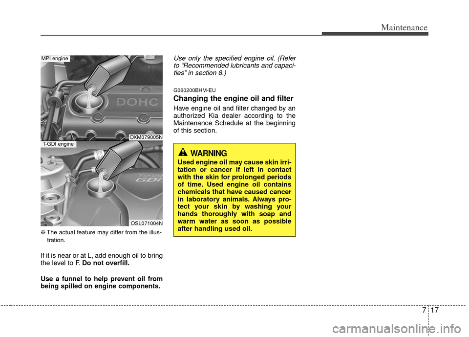
❈The actual feature may differ from the illus-
tration.
If it is near or at L, add enough oil to bring
the level to F. Do not overfill.
Use a funnel to help prevent oil from
being spilled on engine components.
Use only the specified engine oil. (Refer to “Recommended lubricants and capaci-ties” in section 8.)
G060200BHM-EU
Changing the engine oil and filter
Have engine oil and filter changed by an
authorized Kia dealer according to the
Maintenance Schedule at the beginning
of this section.
OXM079005N
OSL071004N
MPI engine
T-GDI engine
WARNING
Used engine oil may cause skin irri-
tation or cancer if left in contact
with the skin for prolonged periods
of time. Used engine oil contains
chemicals that have caused cancer
in laboratory animals. Always pro-
tect your skin by washing your
hands thoroughly with soap and
warm water as soon as possible
after handling used oil.
Page 339 of 387
721
Maintenance
BRAKE/CLUTCH (IF EQUIPPED) FLUID
G080100AAM
Checking the brake/clutch* fluid
level
Check the fluid level in the reservoir peri-
odically. The fluid level should be
between MAX and MIN marks on the
side of the reservoir.
Before removing the reservoir cap and
adding brake/clutch* fluid, clean the area
around the reservoir cap thoroughly to
prevent brake/clutch* fluid contamina-
tion.
* if equippedIf the level is low, add fluid to the MAX
level. The level will fall with accumulated
mileage. This is a normal condition asso-
ciated with the wear of the brake linings
and/or clutch disc (if equipped). If the
fluid level is excessively low, have the
brake/clutch* system checked by an
authorized Kia dealer.
Use only the specified brake/clutch* fluid.
(Refer to “Recommended lubricants andcapacities” in section 8.)
Never mix different types of fluid.
WARNING - Loss of
brake/clutch* fluid
In the event the brake/clutch* sys-
tem requires frequent additions of
fluid, the vehicle should be inspect-
ed by an authorized Kia dealer.
OLM079008
WARNING - Brake/clutch*
fluid
When changing and adding
brake/clutch* fluid, handle it care-
fully. Do not let it come in contact
with your eyes. If brake/clutch* fluid
should come in contact with your
eyes, immediately flush them with a
large quantity of fresh tap water.
Have your eyes examined by a doc-
tor as soon as possible.
CAUTION
Do not allow brake/clutch* fluid to
contact the vehicle's body paint, aspaint damage will result.
Brake/clutch* fluid, which has beenexposed to open air for an extendedtime should never be used as its quality cannot be guaranteed. Itshould be disposed of properly. Don't put in the wrong kind of fluid.A few drops of mineral-based oil, such as engine oil, in yourbrake/clutch* system can damagebrake/clutch* system parts.
Page 347 of 387
729
Maintenance
G190200AUN
Battery recharging
Your vehicle has a maintenance-free,
calcium-based battery.
If the battery becomes discharged in ashort time (because, for example, the
headlights or interior lights were left on
while the vehicle was not in use),
recharge it by slow charging (trickle)
for 10 hours.
If the battery gradually discharges because of high electric load while the
vehicle is being used, recharge it at 20-
30A for two hours.
(Continued)
The electrical ignition systemworks with high voltage. Never
touch these components with the
engine running or the ignition
switched on.
Failure to follow the above warn-
ings can result in serious bodily
injury or death.WARNING- Recharging battery
When recharging the battery,
observe the following precautions:
The battery must be removed
from the vehicle and placed in an
area with good ventilation.
Do not allow cigarettes, sparks, or flame near the battery.
Watch the battery during charg- ing, and stop or reduce the charg-
ing rate if the battery cells begin
gassing (boiling) violently or if
the temperature of the electrolyte
of any cell exceeds 49°C (120°F).
Wear eye protection when check- ing the battery during charging.
Disconnect the battery charger in the following order.
1. Turn off the battery charger main switch.
2. Unhook the negative clamp from the negative battery terminal.
3. Unhook the positive clamp from the positive battery terminal.
CAUTION
If you connect unauthorized elec-tronic devices to the battery, thebattery may be discharged. Never use unauthorized devices.
Page 359 of 387
741
Maintenance
G201100AAM
Tire terminology and definitions
Air Pressure: The amount of air
inside the tire pressing outward on
the tire. Air pressure is expressed in
kilopascal (kPa) or pounds per
square inch (psi).
Accessory Weight: This means the
combined weight of optional acces-
sories. Some examples of optional
accessories are, automatic
transaxle, power seats, and air con-
ditioning.
Aspect Ratio : The relationship of a
tire's height to its width.
Belt: A rubber coated layer of cords
that is located between the plies and
the tread. Cords may be made from
steel or other reinforcing materials.
Bead: The tire bead contains steel
wires wrapped by steel cords that
hold the tire onto the rim.
Bias Ply Tire : A pneumatic tire in
which the plies are laid at alternate
angles less than 90 degrees to the
centerline of the tread. Cold Tire Pressure: The amount of
air pressure in a tire, measured in
kilopascals (kPa) or pounds per
square inch (psi) before a tire has
built up heat from driving.
Curb Weight: This means the weight
of a motor vehicle with standard and
optional equipment including the
maximum capacity of fuel, oil and
coolant, but without passengers and
cargo.
DOT Markings: The DOT code
includes the Tire Identification
Number (TIN), an alphanumeric des-
ignator which can also identify the
tire manufacturer, production plant,
brand and date of production.
GVWR: Gross Vehicle Weight Rating
GAWR FRT: Gross Axle Weight
Rating for the Front Axle.
GAWR RR: Gross Axle Weight
Rating for the Rear axle.
Intended Outboard Sidewall
: The
side of an asymmetrical tire, that
must always face outward when
mounted on a vehicle.
Kilopascal (kPa): The metric unit for
air pressure.
Load Index: An assigned number
ranging from 1 to 279 that corre-
sponds to the load carrying capacity
of a tire.
Maximum Inflation Pressure : The
maximum air pressure to which a
cold tire may be inflated. The maxi-
mum air pressure is molded onto the
sidewall.
Maximum Load Rating : The load
rating for a tire at the maximum per-
missible inflation pressure for that
tire.
Maximum Loaded Vehicle Weight:
The sum of curb weight; accessory
weight; vehicle capacity weight; and
production options weight.
Normal Occupant Weight: The
number of occupants a vehicle is
designed to seat multiplied by 68 kg
(150 pounds).
Page 362 of 387
Maintenance
44
7
FUSES
G210000AAM
A vehicle’s electrical system is protected
from electrical overload damage by
fuses.
This vehicle has 3 fuse panels, one locat-
ed in the driver’s side panel bolster, the
other in the engine compartment near
the battery.
If any of your vehicle’s lights, acces-
sories, or controls do not work, check the
appropriate circuit fuse. If a fuse has
blown, the element inside the fuse will
melt.
If the electrical system does not work,
first check the driver’s side fuse panel.
Always replace a blown fuse with one of
the same rating.
If the replacement fuse blows, this indi-
cates an electrical problem. Avoid using
the system involved and immediately
consult an authorized Kia dealer.
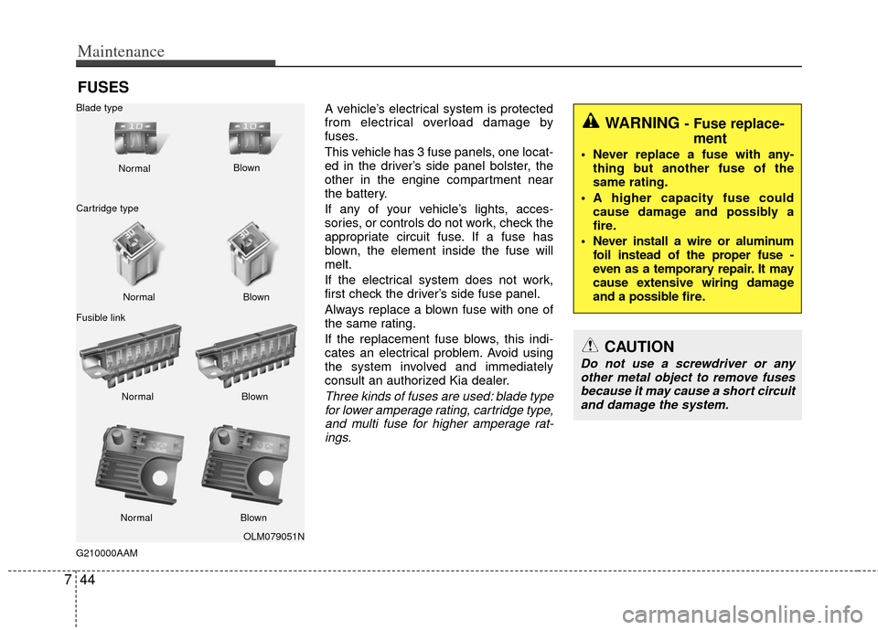
Three kinds of fuses are used: blade type
for lower amperage rating, cartridge type,and multi fuse for higher amperage rat-ings.
WARNING - Fuse replace- ment
Never replace a fuse with any-
thing but another fuse of the
same rating.
A higher capacity fuse could cause damage and possibly a
fire.
Never install a wire or aluminum foil instead of the proper fuse -
even as a temporary repair. It may
cause extensive wiring damage
and a possible fire.
CAUTION
Do not use a screwdriver or anyother metal object to remove fusesbecause it may cause a short circuitand damage the system.
OLM079051N
Normal
Normal
Blade type
Cartridge type
Fusible link Blown
Blown
Normal Blown
Normal Blown
Page 370 of 387
Maintenance
52
7
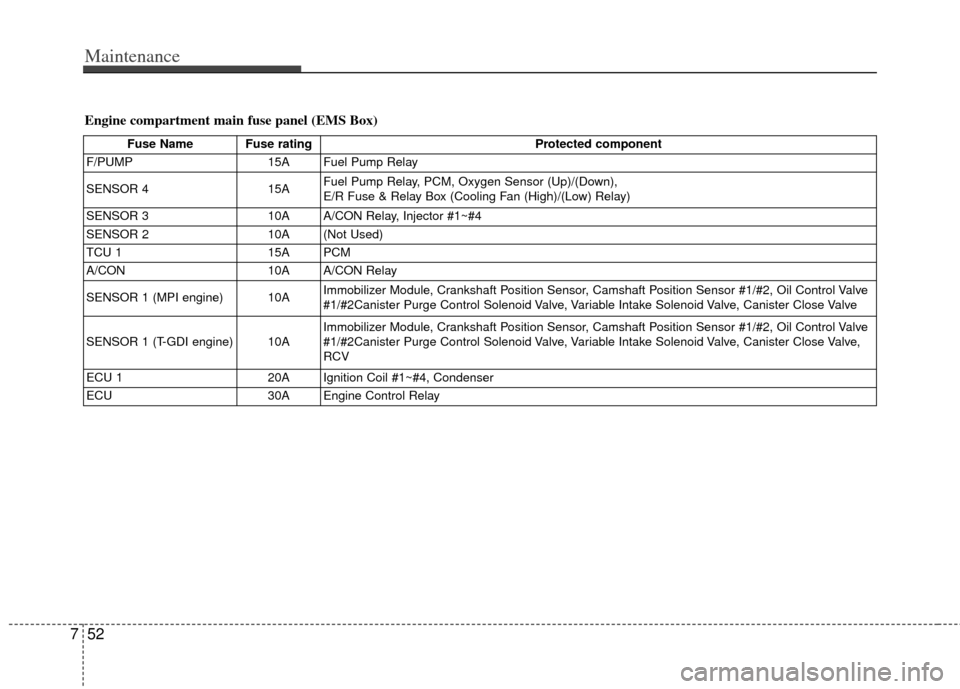
Fuse Name Fuse rating Protected component
F/PUMP 15A Fuel Pump Relay
SENSOR 4 15AFuel Pump Relay, PCM, Oxygen Sensor (Up)/(Down),
E/R Fuse & Relay Box (Cooling Fan (High)/(Low) Relay)
SENSOR 3 10A A/CON Relay, Injector #1~#4
SENSOR 2 10A (Not Used)
TCU 1 15A PCM
A/CON 10A A/CON Relay
SENSOR 1 (MPI engine) 10A Immobilizer Module, Crankshaft Position Sensor, Camshaft Position Sensor #1/#2, Oil Control Valve
#1/#2Canister Purge Control Solenoid Valve, Variable Intake Solenoid Valve, Canister Close Valve
SENSOR 1 (T-GDI engine) 10A Immobilizer Module, Crankshaft Position Sensor, Camshaft Position Sensor #1/#2, Oil Control Valve
#1/#2Canister Purge Control Solenoid Valve, Variable Intake Solenoid Valve, Canister Close Valve,
RCV
ECU 1 20A Ignition Coil #1~#4, Condenser
ECU 30A Engine Control Relay
Engine compartment main fuse panel (EMS Box)