sensor KIA Sportage 2013 SL / 3.G Owner's Guide
[x] Cancel search | Manufacturer: KIA, Model Year: 2013, Model line: Sportage, Model: KIA Sportage 2013 SL / 3.GPages: 387, PDF Size: 8.44 MB
Page 179 of 387
489
Features of your vehicle
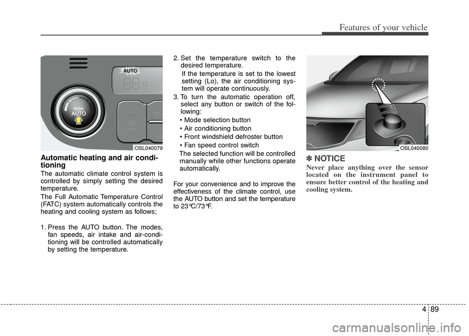
Automatic heating and air condi-
tioning
The automatic climate control system is
controlled by simply setting the desired
temperature.
The Full Automatic Temperature Control
(FATC) system automatically controls the
heating and cooling system as follows;
1. Press the AUTO button. The modes,fan speeds, air intake and air-condi-
tioning will be controlled automatically
by setting the temperature. 2. Set the temperature switch to the
desired temperature.
If the temperature is set to the lowest
setting (Lo), the air conditioning sys-
tem will operate continuously.
3. To turn the automatic operation off, select any button or switch of the fol-
lowing:
The selected function will be controlled manually while other functions operate
automatically.
For your convenience and to improve the
effectiveness of the climate control, use
the AUTO button and set the temperature
to 23°C/73°F.
✽ ✽ NOTICE
Never place anything over the sensor
located on the instrument panel to
ensure better control of the heating and
cooling system.
OSL040080OSL040079
Page 314 of 387
615
What to do in an emergency
TOWING
F080100AAM-EU
Towing service
If emergency towing is necessary, we
recommend having it done by an author-
ized Kia dealer or a commercial tow-truck
service. Proper lifting and towing proce-
dures are necessary to prevent damage
to the vehicle. The use of wheel dollies or
flatbed is recommended.
For trailer towing guidelines information,refer to “Trailer towing” in section 5.
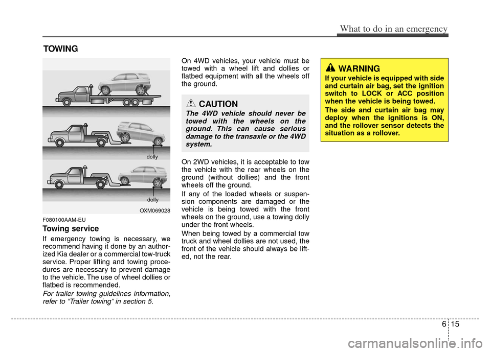
On 4WD vehicles, your vehicle must be
towed with a wheel lift and dollies or
flatbed equipment with all the wheels off
the ground.
On 2WD vehicles, it is acceptable to tow
the vehicle with the rear wheels on the
ground (without dollies) and the front
wheels off the ground.
If any of the loaded wheels or suspen-
sion components are damaged or the
vehicle is being towed with the front
wheels on the ground, use a towing dolly
under the front wheels.
When being towed by a commercial tow
truck and wheel dollies are not used, the
front of the vehicle should always be lift-
ed, not the rear.
OXM069028 dolly
dolly
CAUTION
The 4WD vehicle should never be
towed with the wheels on theground. This can cause seriousdamage to the transaxle or the 4WDsystem.
WARNING
If your vehicle is equipped with side
and curtain air bag, set the ignition
switch to LOCK or ACC position
when the vehicle is being towed.
The side and curtain air bag may
deploy when the ignitions is ON,
and the rollover sensor detects the
situation as a rollover.
Page 341 of 387
723
Maintenance
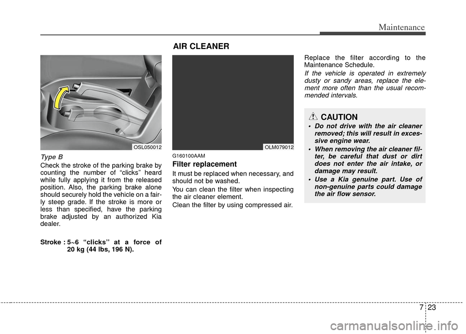
Type B
Check the stroke of the parking brake by
counting the number of “clicks’’ heard
while fully applying it from the released
position. Also, the parking brake alone
should securely hold the vehicle on a fair-
ly steep grade. If the stroke is more or
less than specified, have the parking
brake adjusted by an authorized Kia
dealer.
Stroke :5~6 “clicks’’ at a force of
20 kg (44 lbs, 196 N).
G160100AAM
Filter replacement
It must be replaced when necessary, and
should not be washed.
You can clean the filter when inspecting
the air cleaner element.
Clean the filter by using compressed air. Replace the filter according to the
Maintenance Schedule.
If the vehicle is operated in extremely
dusty or sandy areas, replace the ele- ment more often than the usual recom-mended intervals.
AIR CLEANER
OSL050012OLM079012
CAUTION
Do not drive with the air cleaner removed; this will result in exces-sive engine wear.
When removing the air cleaner fil- ter, be careful that dust or dirtdoes not enter the air intake, or damage may result.
Use a Kia genuine part. Use of non-genuine parts could damagethe air flow sensor.
Page 367 of 387
749
Maintenance
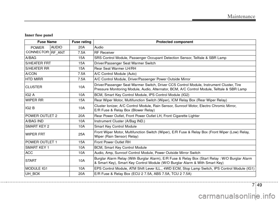
Inner fuse panel
Fuse Name Fuse ratingProtected component
POWER
CONNECTOR
AUDIO 20A Audio
RF_ANT 7.5A RF Receiver
A/BAG 15A SRS Control Module, Passenger Occupant Detection Sensor, Telltale & SBR Lamp
S/HEATER FRT 15A Driver/Passenger Seat Warmer Switch
S/HEATER RR 15A Rear Seat Warmer LH/RH
A/CON 7.5A A/C Control Module (Auto)
HTD MIRR 7.5A A/C Control Module, Driver/Passenger Power Outside Mirror
CLUSTER 10A Driver/Passenger Seat Warmer Switch, Driver CCS Control Module, Instrument Cluster, Tire
Pressure Monitoring Module, Audio, Alternator, BCM, A/C Control Module, Telltale & SBR Lamp
IG2 A 10A BCM, Smart Key Control Module, IPS Control Module (IG2)
WIPER RR 15A Rear Wiper Motor, Multifunction Switch (Wiper), ICM Relay Box (Rear Wiper Relay)
IG2 B 10A Cluster Ionizer, A/C Control Module, Rain Sensor, Sunroof Motor, Electro Chromic Mirror,
E/R Fuse & Relay Box (Blower Relay)
POWER OUTLET 2 20A Rear Power Outlet, Front Power Outlet LH, Front Cigarette Lighter
A/BAG IND 10A Instrument Cluster (A/Bag IND.)
SMART KEY 2 10A Smart Key Control Module
WIPER FRT 25A Front Wiper Motor, Multifunction Switch (Wiper), E/R Fuse & Relay Box (Front Wiper (Low) Relay,
Wiper (Rain Sensor) Relay)
POWER OUTLET 1 15A Front Power Outlet RH
SMART KEY 1 10A BCM, Smart Key Control Module
ACC 10A Audio, Amp, Sunroof Control Module, Power Outside Mirror Switch
START 10A Burglar Alarm Relay (With Burglar Alarm), E/R Fuse & Relay Box (Start Relay : W/O Burglar Alarm
& Smart Key), Smart Key Control Module (W/O Burglar Alarm & With Smart Key)
MODULE IG1 10A EPS Control Module, ATM Shift Lever ILL., 4WD ECM, Stop Lamp Switch, IPS Control Module (IG1)
UH_BOX 20A E/R Fuse & Relay Box (ECU 2 7.5A, ABS 7.5A, TCU 2 7.5A)
Page 369 of 387
751
Maintenance
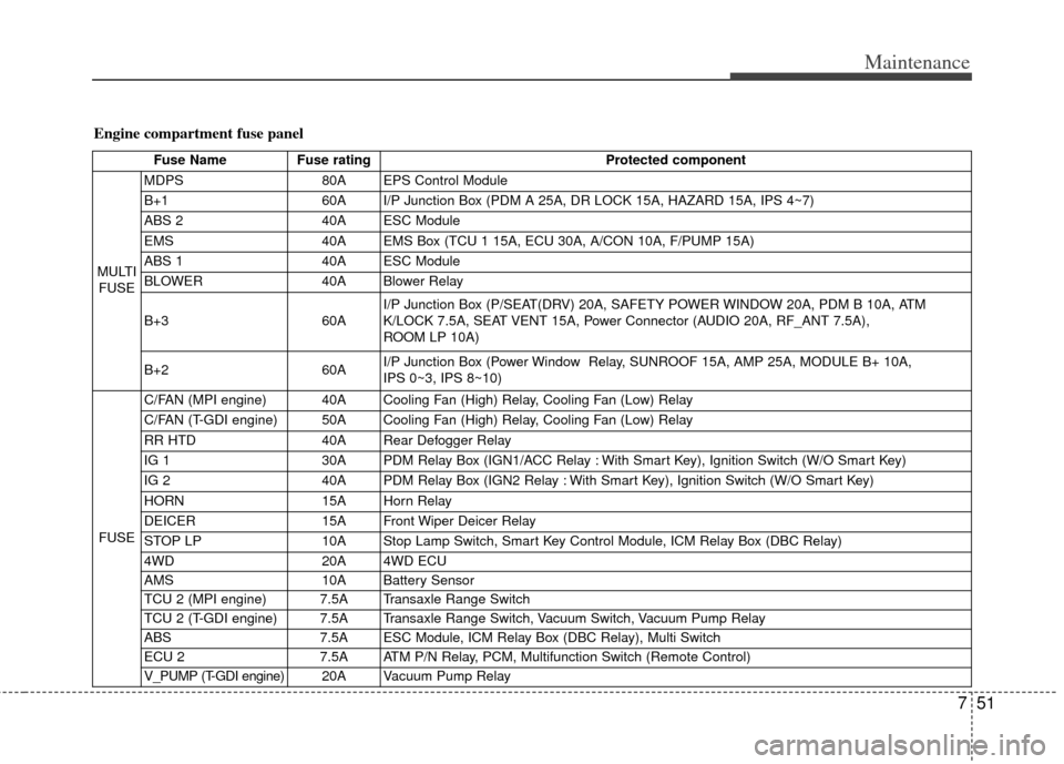
Engine compartment fuse panel
Fuse NameFuse rating Protected component
MULTI FUSE MDPS
80A EPS Control Module
B+1 60A I/P Junction Box (PDM A 25A, DR LOCK 15A, HAZARD 15A, IPS 4~7)
ABS 2 40A ESC Module
EMS 40A EMS Box (TCU 1 15A, ECU 30A, A/CON 10A, F/PUMP 15A)
ABS 1 40A ESC Module
BLOWER 40A Blower Relay
B+3 60AI/P Junction Box (P/SEAT(DRV) 20A, SAFETY POWER WINDOW 20A, PDM B 10A, ATM
K/LOCK 7.5A, SEAT VENT 15A, Power Connector (AUDIO 20A, RF_ANT 7.5A),
ROOM LP 10A)
B+2 60AI/P Junction Box (Power Window Relay, SUNROOF 15A, AMP 25A, MODULE B+ 10A,
IPS 0~3, IPS 8~10)
FUSE C/FAN (MPI engine) 40A Cooling Fan (High) Relay, Cooling Fan (Low) Relay
C/FAN (T-GDI engine) 50A Cooling Fan (High) Relay, Cooling Fan (Low) Relay
RR HTD
40A Rear Defogger Relay
IG 1 30A PDM Relay Box (IGN1/ACC Relay : With Smart Key), Ignition Switch (W/O Smart Key)
IG 2 40A PDM Relay Box (IGN2 Relay : With Smart Key), Ignition Switch (W/O Smart Key)
HORN 15A Horn Relay
DEICER 15A Front Wiper Deicer Relay
STOP LP 10A Stop Lamp Switch, Smart Key Control Module, ICM Relay Box (DBC Relay)
4WD 20A 4WD ECU
AMS 10A Battery Sensor
TCU 2 (MPI engine) 7.5A Transaxle Range Switch
TCU 2 (T-GDI engine) 7.5A Transaxle Range Switch, Vacuum Switch, Vacuum Pump Relay
ABS 7.5A ESC Module, ICM Relay Box (DBC Relay), Multi Switch
ECU 2 7.5A ATM P/N Relay, PCM, Multifunction Switch (Remote Control)
V_PUMP (T-GDI engine) 20A V acuum Pump Relay
Page 370 of 387
Maintenance
52
7
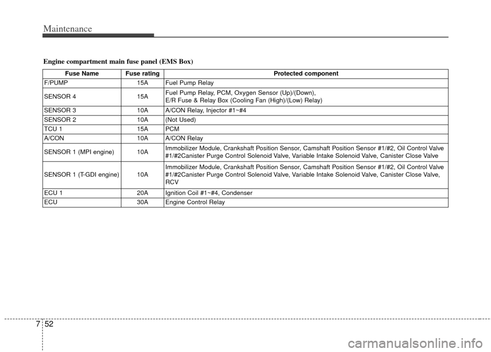
Fuse Name Fuse rating Protected component
F/PUMP 15A Fuel Pump Relay
SENSOR 4 15AFuel Pump Relay, PCM, Oxygen Sensor (Up)/(Down),
E/R Fuse & Relay Box (Cooling Fan (High)/(Low) Relay)
SENSOR 3 10A A/CON Relay, Injector #1~#4
SENSOR 2 10A (Not Used)
TCU 1 15A PCM
A/CON 10A A/CON Relay
SENSOR 1 (MPI engine) 10A Immobilizer Module, Crankshaft Position Sensor, Camshaft Position Sensor #1/#2, Oil Control Valve
#1/#2Canister Purge Control Solenoid Valve, Variable Intake Solenoid Valve, Canister Close Valve
SENSOR 1 (T-GDI engine) 10A Immobilizer Module, Crankshaft Position Sensor, Camshaft Position Sensor #1/#2, Oil Control Valve
#1/#2Canister Purge Control Solenoid Valve, Variable Intake Solenoid Valve, Canister Close Valve,
RCV
ECU 1 20A Ignition Coil #1~#4, Condenser
ECU 30A Engine Control Relay
Engine compartment main fuse panel (EMS Box)