engine KIA STINGER 2021 Owners Manual
[x] Cancel search | Manufacturer: KIA, Model Year: 2021, Model line: STINGER, Model: KIA STINGER 2021Pages: 585, PDF Size: 10.87 MB
Page 509 of 585

757
Maintenance
✽ ✽
NOTICE- Remodeling
Prohibited
Do not rewire your vehicle in any
way as doing so may affect the per-
formance of several safety features
in your vehicle. Rewiring your vehi-
cle may also void your warranty and
cause you to be responsible for any
subsequent vehicle damage which
may result.
✽ ✽
NOTICE- Window tinting
precaution
Window tint(especially metallic
film) might cause communication
disorder or poor radio reception,
and malfunction of the automatic
lighting system due to excessive
change of illumination inside the
vehicle. The solution used might also
flow into electric, electronic devices
causing disorder and failure.
Inner panel fuse replacement
1. Turn the ignition switch and all
other switches off.
2. Open the fuse panel cover.
If the switch is located in the “OFF”
position, a caution indicator will be
displayed in the cluster.
CAUTION
Visually inspect the battery cap
to ensure it is securely closed.
If the battery cap is not securely
closed, moisture may enter the
system and damage the electri-
cal components.
WARNING
- Electrical wiring repairs
All electrical repairs should be
performed by authorized Kia
dealerships using approved Kia
parts. Using other wiring com-
ponents, especially when retro-
fitting AVN or theft alarm sys-
tem, remote engine control, car
phone or radio may cause vehi-
cle damage and increase the
risk of a vehicle fire.
OCK077032
Page 510 of 585

Maintenance
58 7
3. Pull the suspected fuse straight
out. Use the removal tool provided
on the engine compartment fuse
panel cover.
4. Check the removed fuse; replace it
if it is blown.
Spare fuses are provided in the
engine compartment fuse panel.
5. Push in a new fuse of the same
rating, and make sure it fits tightly
in the clips.
If it fits loosely, consult an authorized
Kia dealer.
If you do not have a spare, use a
fuse of the same rating from a circuit
you may not need for operating the
vehicle, such as the power outlet
fuse.
If the head lamp, turn signal lamp,
stop signal lamp, fog lamp, DRL, tail
lamp, HMSL do not work and the
fuses are OK, check the fuse panel
in the engine compartment. If a fuse
is blown, it must be replaced.
✽ ✽
NOTICE
If the headlamp, fog lamp, turn sig-
nal lamp, or tail lamp malfunction
even without any problem to the
lamps, have the vehicle checked by
an authorized Kia dealer for assis-
tance.
Fuse switch
Always set the fuse switch to the ON
position before using the vehicle.
If you move the switch to the OFF
position, some items such as audio
and digital clock must be reset and
transmitter (or smart key) may not
work properly. When the switch is
Off, the caution indicator will be dis-
played on the instrument cluster.
Always place the fuse switch in the
ON position while driving the vehicle.
If the switch is located in the “OFF”
position, a caution indicator will be
displayed in the cluster.
OCK077033
OCK077034
Page 511 of 585

759
Maintenance
✽ ✽
NOTICE
• Set all switches to ON before driv-
ing.
• If the vehicle is going to be unused
for over 1 month, set all switches
to OFF to prevent the batteries
from draining.
Engine compartment fuse
replacement
1. Turn the ignition switch and all
other switches off.
2. Remove the fuse panel cover by
pressing the tab and pulling the
cover up. When the blade type
fuse is disconnected, remove it by
using the clip designed for chang-
ing fuses located in the engine
compartment fuse box. Upon
removal, securely insert reserve
fuse of the same rating.3. Check the removed fuse; replace it
if it is blown. To remove or insert
the fuse, use the fuse puller in the
engine compartment fuse panel.
4. Push in a new fuse of the same
rating, and make sure it fits tightly
in the clips. If it fits loosely, consult
an authorized Kia dealer.
CAUTION
Always securely install the fuse
panel cover in the engine com-
partment to protect against
electrical failure which may
occur from water contact.
Listen for the audible clicking
sound to ensure fuse panel
cover is securely fastened.
CAUTION - Fuse Panel
Covers
The contact points of the
switches may wear out with
excessive use. Please refrain
from excessive use of the
switches (except for long-term
parking for over 1 month).
OCK077035
Page 512 of 585

Maintenance
60 7
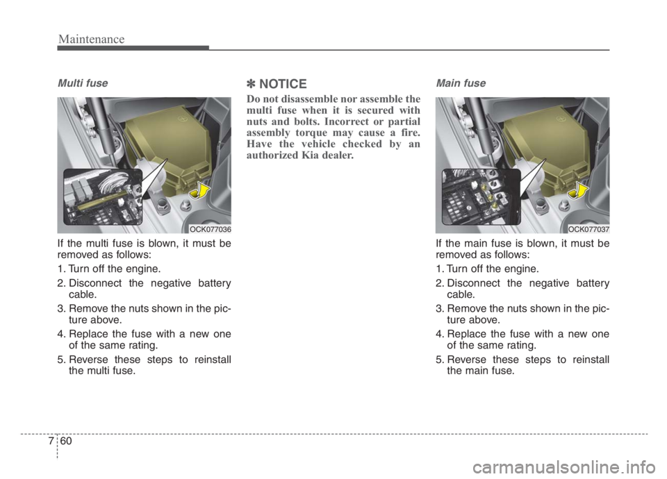
Multi fuse
If the multi fuse is blown, it must be
removed as follows:
1. Turn off the engine.
2. Disconnect the negative battery
cable.
3. Remove the nuts shown in the pic-
ture above.
4. Replace the fuse with a new one
of the same rating.
5. Reverse these steps to reinstall
the multi fuse.
✽ ✽
NOTICE
Do not disassemble nor assemble the
multi fuse when it is secured with
nuts and bolts. Incorrect or partial
assembly torque may cause a fire.
Have the vehicle checked by an
authorized Kia dealer.
Main fuse
If the main fuse is blown, it must be
removed as follows:
1. Turn off the engine.
2. Disconnect the negative battery
cable.
3. Remove the nuts shown in the pic-
ture above.
4. Replace the fuse with a new one
of the same rating.
5. Reverse these steps to reinstall
the main fuse.
OCK077037OCK077036
Page 513 of 585

761
Maintenance
✽ ✽
NOTICE
The electronic system may not func-
tion correctly even when the engine
compartment and internal fuse
box’s individual fuses are not dis-
connected. In such case the cause of
the problem may be disconnection
of the main fuse.
Since the main fuse is designed more
intricately than other parts, have the
vehicle checked by an authorized
Kia dealer.
Fuse/relay panel description
■Engine compartment fuse panel
■Driver’s side fuse panel
OCK077040
■Battery box fuse panel
■Rear fuse box panel
OCK077043
OCK077045
OCK077038
Inside the fuse/relay panel covers, you can find the fuse/relay label
describing fuse/relay name and capacity.
Page 519 of 585

767
Maintenance
Fuse NameFuse ratingCircuit Protected
WASHER15AMultifunction Switch
MDPS10AMDPS (Motor Driven Power Steering) Unit (R-MDPS (Motor Driven Power Steering))
P/SEAT (DRV)30ADriver Integrated memory system Control Module, Drive Seat Module
P/SEAT (PASS)30APassenger Seat Module
P/WINDOW LH25ADriver Power Window Module, Rear Power Window Module Left Handle side
MODULE 610AIBU, Low DC-DC Converter (Audio/AMP (Amplifier)), Electronic Auto Transmission Shift Lever (SBW
(Shift By Wire)), Engine Room Junction Block (RLY. 4 - Power Outlet Relay)
A/C10AAir Conditioner Control Module, Air Conditioner Switch, Engine Room Junction Block (Blower Relay)
MODULE 410AHead Lamp Left Handle side/Right Handle side, AFS Control Unit, Auto Head Lamp Leveling Device Module
Page 520 of 585

Maintenance
68 7
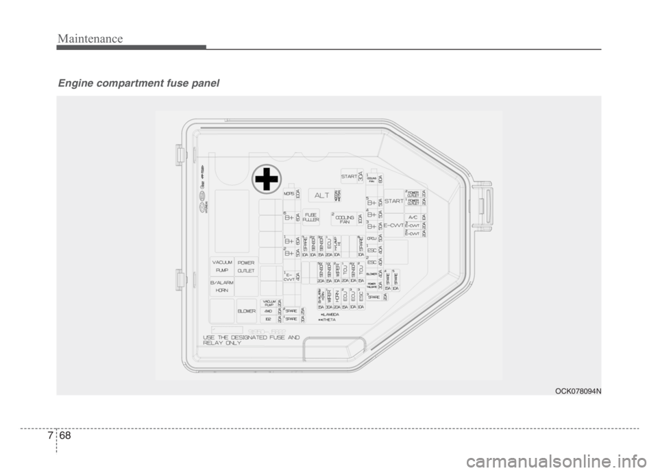
Engine compartment fuse panel
OCK078094N
Page 521 of 585

769
Maintenance
Fuse NameFuse ratingCircuit Protected
ALT175A
200AAlternator, Multi Fuse
- COOLING FAN 1 / B+5 / B+4 / B+3 / OPCU / ESC1 / ESC2 / BLOWER / POWER TAIL GATE
COOLING FAN 2100A[BLDC (Brushless Direct Current) Motor] Cooling Fan Controller
START30AStart Relay
COOLING FAN 180A[BLDC (Brushless Direct Current) Motor] Cooling Fan Controller
B+550AInstrument Panel Junction Block
(Fuse - STOP LAMP / Leak Current Autocut Device Fuse / INTERIOR LAMP)
B+450AInstrument Panel Junction Block
(Fuse - DOOR LOCK / POWER HANDLE / SUNROOF / P/SEAT (DRV) / P/SEAT (PASS))
B+350AInstrument Panel Junction Block
(Fuse - S/HEATER DRV/PASS / TAIL GATE / MODULE9 / P/WINDOW RH / P/WINDOW LH)
OPCU50AElectric Oil Pump Inverter
ESC 140AESC (Electronic Stability Control) Control Module
ESC 240AESC (Electronic Stability Control) Control Module, Multipurpose Check Connector
BLOWER40ABlower Relay
POWER TAIL GATE30APower Tail Gate Module
Engine room compartment fuse panel
Page 522 of 585

Maintenance
70 7
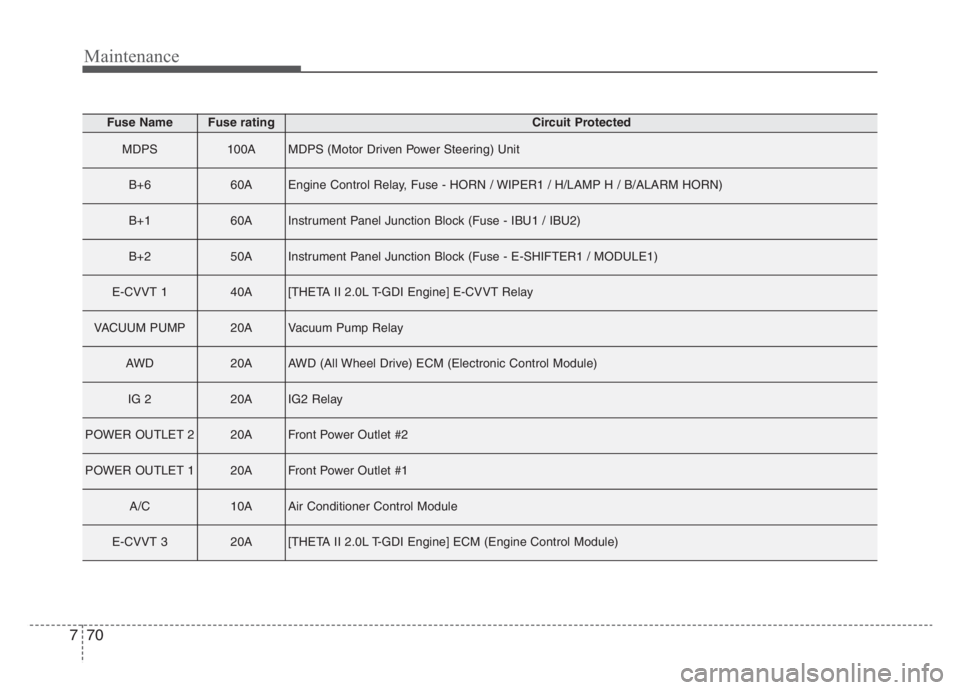
Fuse NameFuse ratingCircuit Protected
MDPS100AMDPS (Motor Driven Power Steering) Unit
B+660AEngine Control Relay, Fuse - HORN / WIPER1 / H/LAMP H / B/ALARM HORN)
B+160AInstrument Panel Junction Block (Fuse - IBU1 / IBU2)
B+250AInstrument Panel Junction Block (Fuse - E-SHIFTER1 / MODULE1)
E-CVVT 140A[THETA II 2.0L T-GDI Engine] E-CVVT Relay
VACUUM PUMP20AVacuum Pump Relay
AWD20AAWD (All Wheel Drive) ECM (Electronic Control Module)
IG 220AIG2 Relay
POWER OUTLET 220AFront Power Outlet #2
POWER OUTLET 120AFront Power Outlet #1
A/C10AAir Conditioner Control Module
E-CVVT 320A[THETA II 2.0L T-GDI Engine] ECM (Engine Control Module)
Page 523 of 585
![KIA STINGER 2021 Owners Manual 771
Maintenance
Fuse NameFuse ratingCircuit Protected
E-CVVT 220A[THETA II 2.0L T-GDI Engine] ECM (Engine Control Module)
ESC 310AESC (Electronic Stability Control) Control Module, Multipurpose Check KIA STINGER 2021 Owners Manual 771
Maintenance
Fuse NameFuse ratingCircuit Protected
E-CVVT 220A[THETA II 2.0L T-GDI Engine] ECM (Engine Control Module)
ESC 310AESC (Electronic Stability Control) Control Module, Multipurpose Check](/img/2/55166/w960_55166-522.png)
771
Maintenance
Fuse NameFuse ratingCircuit Protected
E-CVVT 220A[THETA II 2.0L T-GDI Engine] ECM (Engine Control Module)
ESC 310AESC (Electronic Stability Control) Control Module, Multipurpose Check Connector
ECU 310AECM (Engine Control Module)
ECU 215AECM (Engine Control Module)
HORN20AHorn Relay
WIPER 130AWiper Power Relay
TCU 215ATCM (Transmission Control Module)
SENSOR 410ABrake Vacuum Switch, Vacuum Pump Relay, Electric Oil Pump Inverter
TCU 120ATCM (Transmission Control Module)
WIPER 210AIBU (Integrated Body Control Unit), ECM (Electronic Control Module)
SENSOR 115ARear Sub Junction Block (Fuel Pump Relay)
SENSOR520A[THETA II 2.0L T-GDI Engine] Ignition Coil #1/#2/#3/#4
[Lambda II PE 3.3L T-GDI Engine] Ignition Coil #1/#2/#3/#4/#5/#6