lock KIA VENGA 2011 Owners Manual
[x] Cancel search | Manufacturer: KIA, Model Year: 2011, Model line: VENGA, Model: KIA VENGA 2011Pages: 761, PDF Size: 34.65 MB
Page 684 of 761
Maintenance
44
7
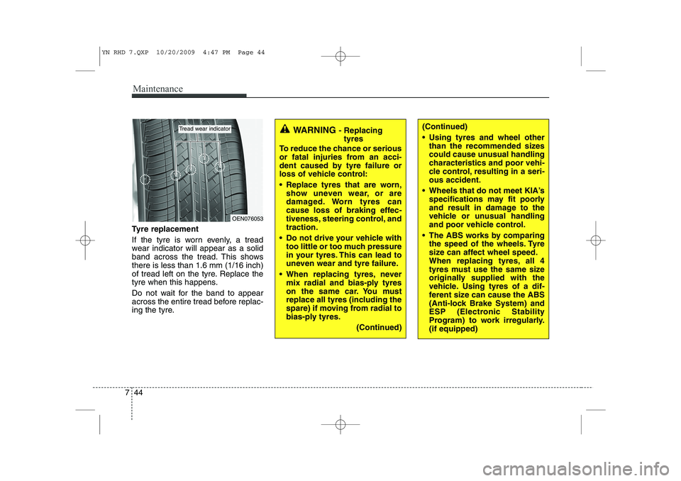
Tyre replacement
If the tyre is worn evenly, a tread
wear indicator will appear as a solid
band across the tread. This showsthere is less than 1.6 mm (1/16 inch)
of tread left on the tyre. Replace the
tyre when this happens.
Do not wait for the band to appear
across the entire tread before replac-
ing the tyre.
OEN076053
Tread wear indicatorWARNING - Replacing
tyres
To reduce the chance or serious
or fatal injuries from an acci-
dent caused by tyre failure or
loss of vehicle control:
Replace tyres that are worn, show uneven wear, or are
damaged. Worn tyres can
cause loss of braking effec-
tiveness, steering control, andtraction.
Do not drive your vehicle with too little or too much pressure
in your tyres. This can lead to
uneven wear and tyre failure.
When replacing tyres, never mix radial and bias-ply tyres
on the same car. You must
replace all tyres (including the
spare) if moving from radial to
bias-ply tyres.
(Continued)(Continued)
Using tyres and wheel otherthan the recommended sizes
could cause unusual handling
characteristics and poor vehi-
cle control, resulting in a seri-ous accident.
Wheels that do not meet KIA’s specifications may fit poorly
and result in damage to the
vehicle or unusual handling
and poor vehicle control.
The ABS works by comparing the speed of the wheels. Tyre
size can affect wheel speed.
When replacing tyres, all 4
tyres must use the same size
originally supplied with the
vehicle. Using tyres of a dif-
ferent size can cause the ABS
(Anti-lock Brake System) and
ESP (Electronic Stability
Program) to work irregularly.(if equipped)
YN RHD 7.QXP 10/20/2009 4:47 PM Page 44
Page 696 of 761
Maintenance
56
7
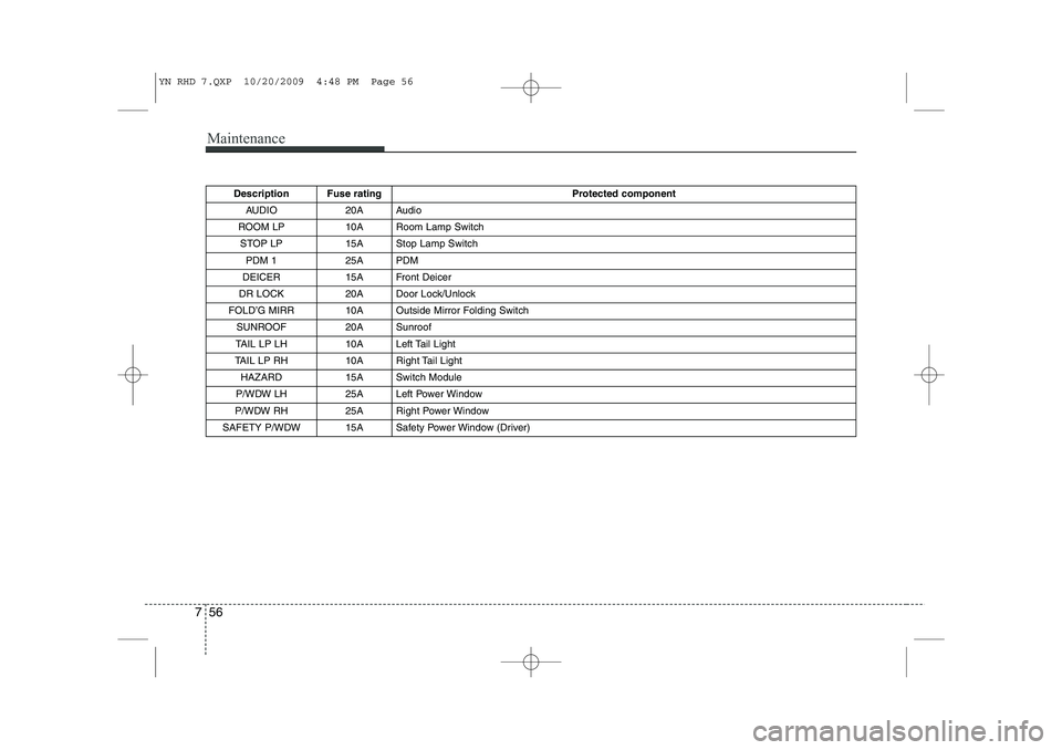
Description Fuse rating Protected component
AUDIO 20A Audio
ROOM LP 10A Room Lamp Switch STOP LP 15A Stop Lamp Switch
PDM 1 25A PDM
DEICER 15A Front Deicer
DR LOCK 20A Door Lock/Unlock
FOLD’G MIRR 10A Outside Mirror Folding Switch SUNROOF 20A Sunroof
TAIL LP LH 10A Left Tail Light
TAIL LP RH 10A Right Tail Light HAZARD 15A Switch Module
P/WDW LH 25A Left Power Window
P/WDW RH 25A Right Power Window
SAFETY P/WDW 15A Safety Power Window (Driver)
YN RHD 7.QXP 10/20/2009 4:48 PM Page 56
Page 697 of 761
757
Maintenance
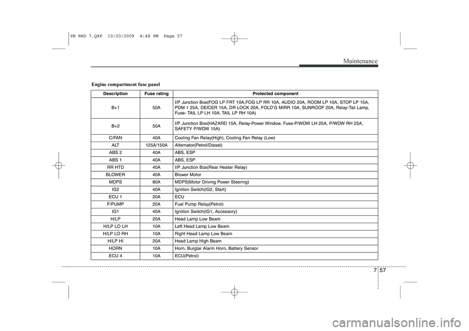
Engine compartment fuse panelDescription Fuse rating Protected component
B+1 50A I/P Junction Box(FOG LP FRT 10A,FOG LP RR 10A, AUDIO 20A, ROOM LP 10A, STOP LP 15A,
PDM 1 25A, DEICER 15A, DR LOCK 20A, FOLD’G MIRR 10A, SUNROOF 20A, Relay-Tail Lamp,
Fuse- TAIL LP LH 10A, TAIL LP RH 10A)
B+2 50A I/P Junction Box(HAZARD 15A, Relay-Power Window, Fuse-P/WDW LH 25A, P/WDW RH 25A,
SAFETY P/WDW 15A)
C/FAN 40A Cooling Fan Relay(High), Cooling Fan Relay (Low) ALT 125A/150A Alternator(Petrol/Diesel)
ABS 2 40A ABS, ESP
ABS 1 40A ABS, ESP
RR HTD 40A I/P Junction Box(Rear Heater Relay)
BLOWER 40A Blower Motor
MDPS 80A MDPS(Motor Driving Power Steering)IG2 40A Ignition Switch(IG2, Start)
ECU 1 20A ECU
F/PUMP 20A Fuel Pump Relay(Petrol) IG1 40A Ignition Switch(IG1, Accessory)
H/LP 20A Head Lamp Low Beam
H/LP LO LH 10A Left Head Lamp Low Beam
H/LP LO RH 10A Right Head Lamp Low Beam
H/LP HI 20A Head Lamp High BeamHORN 10A Horn, Burglar Alarm Horn, Battery Sensor
ECU 4 10A ECU(Petrol)
YN RHD 7.QXP 10/20/2009 4:48 PM Page 57
Page 699 of 761
759
Maintenance
LIGHT BULBS
Use only the bulbs of the specifiedwattage.
✽✽ NOTICE
After heavy, driving rain or washing, headlight and taillight lenses could
appear frosty. This condition is caused by
the temperature difference between the
lamp inside and outside. This is similar
to the condensation on your windows
inside your vehicle during the rain and
doesn’t indicate a problem with your
vehicle. If the water leaks into the lamp
bulb circuitry, have the vehicle checked
by an authorised KIA dealer.
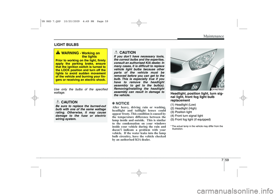
Headlight, position light, turn sig-
nal light, front fog light bulbreplacement
(1) Headlight (Low) (2) Headlight (High)
(3) Position light
(4) Front turn signal light
(5) Front fog light (if equipped)
* The actual lamp in the vehicle may differ from the illustration.
WARNING - Working on
the lights
Prior to working on the light, firmly
apply the parking brake, ensure
that the ignition switch is turned tothe LOCK position and turn off the
lights to avoid sudden movement
of the vehicle and burning your fin-
gers or receiving an electric shock.
CAUTION
Be sure to replace the burned-out bulb with one of the same wattagerating. Otherwise, it may cause
damage to the fuse or electricwiring system.
CAUTION
If you don’t have necessary tools,the correct bulbs and the expertise,
consult an authorised KIA dealer. Inmany cases, it is difficult to replace vehicle light bulbs because otherparts of the vehicle must be
removed before you can get to thebulb. This is especially true if you have to remove the headlight
assembly to
get to the bulb(s).
Removing/installingthe headlight
assembly can result in damage to the vehicle.OYN079027
YN RHD 7.QXP 10/20/2009 4:49 PM Page 59
Page 701 of 761
761
Maintenance
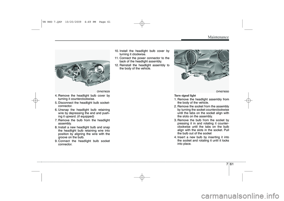
4. Remove the headlight bulb cover byturning it counterclockwise.
5. Disconnect the headlight bulb socket- connector.
6. Unsnap the headlight bulb retaining wire by depressing the end and push-
ing it upward. (if equipped)
7. Remove the bulb from the headlight assembly.
8. Install a new headlight bulb and snap the headlight bulb retaining wire into
position by aligning the wire with the
groove on the bulb.
9. Connect the headlight bulb socket connector. 10. Install the headlight bulb cover by
turning it clockwise.
11. Connect the power connector to the back of the headlight assembly.
12. Reinstall the headlight assembly to the body of the vehicle.
Turn signal light
1. Remove the headlight assembly fromthe body of the vehicle.
2. Remove the socket from the assembly by turning the socket counterclockwise
until the tabs on the socket align with
the slots on the assembly.
3. Remove the bulb from the socket by pressing it in and rotating it counter-
clockwise until the tabs on the bulb
align with the slots in the socket. Pull
the bulb out of the socket
4. Insert a new bulb by inserting it into the socket and rotating it until it locks
into place.
OYN079029OYN079050
YN RHD 7.QXP 10/20/2009 4:49 PM Page 61
Page 702 of 761
Maintenance
62
7
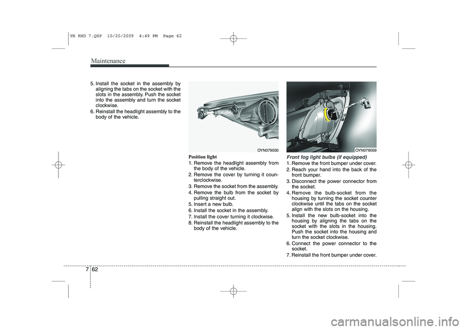
5. Install the socket in the assembly by
aligning the tabs on the socket with the
slots in the assembly. Push the socket
into the assembly and turn the socket
clockwise.
6. Reinstall the headlight assembly to the body of the vehicle.
Position light
1. Remove the headlight assembly fromthe body of the vehicle.
2. Remove the cover by turning it coun- terclockwise.
3. Remove the socket from the assembly.
4. Remove the bulb from the socket by pulling straight out.
5. Insert a new bulb.
6. Install the socket in the assembly.
7. Install the cover turning it clockwise.
8. Reinstall the headlight assembly to the body of the vehicle.
Front fog light bulbs (if equipped)
1. Remove the front bumper under cover.
2. Reach your hand into the back of the
front bumper.
3. Disconnect the power connector from the socket.
4. Remove the bulb-socket from the housing by turning the socket counter
clockwise until the tabs on the socketalign with the slots on the housing.
5. Install the new bulb-socket into the housing by aligning the tabs on the
socket with the slots in the housing.
Push the socket into the housing and
turn the socket clockwise.
6. Connect the power connector to the socket.
7. Reinstall the front bumper under cover.
OYN079030OYN079059
YN RHD 7.QXP 10/20/2009 4:49 PM Page 62
Page 704 of 761
Maintenance
64
7
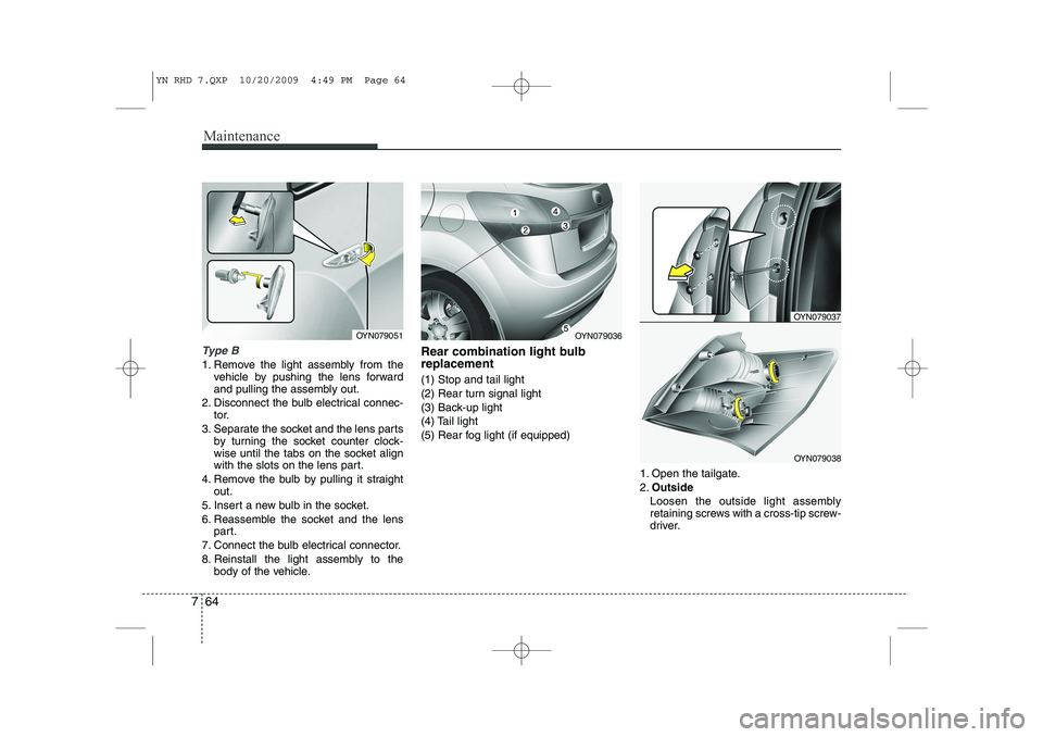
Type B
1. Remove the light assembly from the
vehicle by pushing the lens forward
and pulling the assembly out.
2. Disconnect the bulb electrical connec- tor.
3. Separate the socket and the lens parts by turning the socket counter clock-
wise until the tabs on the socket align
with the slots on the lens part.
4. Remove the bulb by pulling it straight out.
5. Insert a new bulb in the socket.
6. Reassemble the socket and the lens part.
7. Connect the bulb electrical connector.
8. Reinstall the light assembly to the body of the vehicle. Rear combination light bulb replacement (1) Stop and tail light
(2) Rear turn signal light
(3) Back-up light
(4) Tail light
(5) Rear fog light (if equipped)
1. Open the tailgate.2.Outside
Loosen the outside light assembly
retaining screws with a cross-tip screw-
driver.
OYN079051OYN079036
OYN079037
OYN079038
YN RHD 7.QXP 10/20/2009 4:49 PM Page 64
Page 705 of 761
765
Maintenance
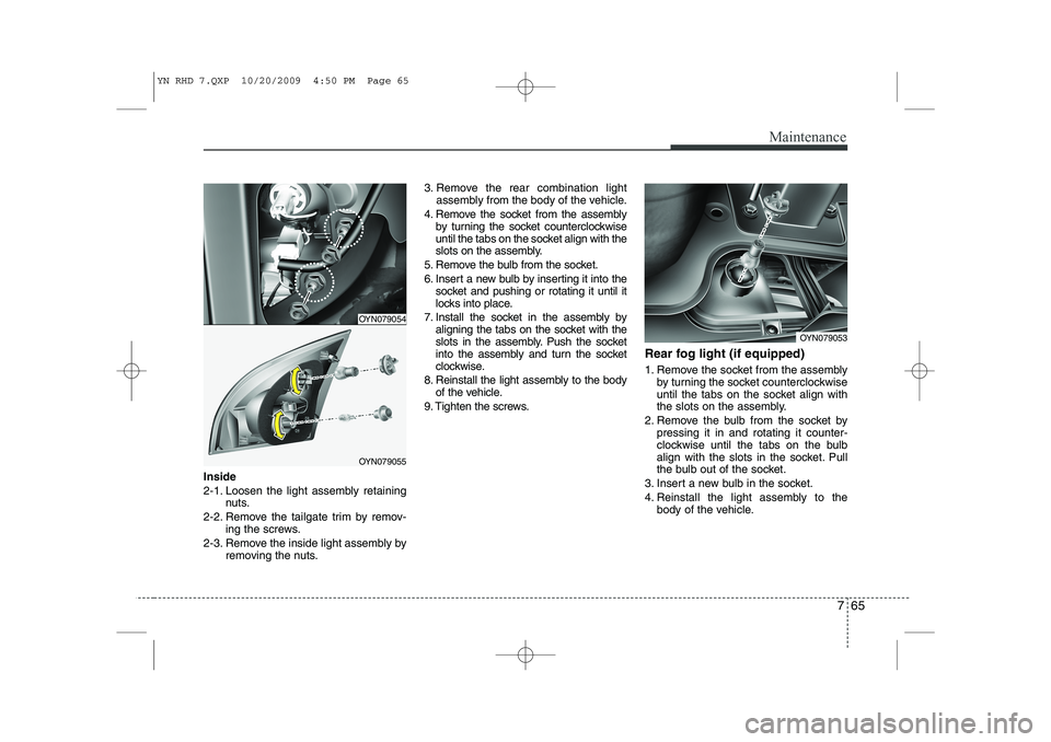
Inside
2-1. Loosen the light assembly retainingnuts.
2-2. Remove the tailgate trim by remov- ing the screws.
2-3. Remove the inside light assembly by removing the nuts. 3. Remove the rear combination light
assembly from the body of the vehicle.
4. Remove the socket from the assembly by turning the socket counterclockwise
until the tabs on the socket align with the
slots on the assembly.
5. Remove the bulb from the socket.
6. Insert a new bulb by inserting it into the socket and pushing or rotating it until it
locks into place.
7. Install the socket in the assembly by aligning the tabs on the socket with the
slots in the assembly. Push the socket
into the assembly and turn the socket
clockwise.
8. Reinstall the light assembly to the body of the vehicle.
9. Tighten the screws. Rear fog light (if equipped)
1. Remove the socket from the assembly
by turning the socket counterclockwise
until the tabs on the socket align with
the slots on the assembly.
2. Remove the bulb from the socket by pressing it in and rotating it counter-
clockwise until the tabs on the bulb
align with the slots in the socket. Pull
the bulb out of the socket.
3. Insert a new bulb in the socket.
4. Reinstall the light assembly to the body of the vehicle.
OYN079054
OYN079055
OYN079053
YN RHD 7.QXP 10/20/2009 4:50 PM Page 65
Page 724 of 761
87
Specifications & Consumer information
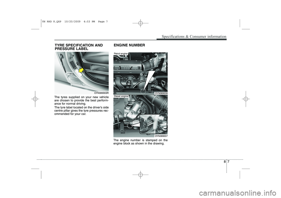
The tyres supplied on your new vehicle
are chosen to provide the best perform-
ance for normal driving.
The tyre label located on the driver's side
centre pillar gives the tyre pressures rec-
ommended for your car.The engine number is stamped on the
engine block as shown in the drawing.
OYN089003R
TYRE SPECIFICATION AND PRESSURE LABEL
OYN089006
Petrol engine
OYN089007
ENGINE NUMBER
Diesel engine
YN RHD 8.QXP 10/20/2009 4:53 PM Page 7
Page 726 of 761
Index
2
I
Air bag - supplemental restraint system . . . . . . . . . 3-37
Air cleaner . . . . . . . . . . . . . . . . . . . . . . . . . . . . . . . . . . 7-33
Appearance care . . . . . . . . . . . . . . . . . . . . . . . . . . . . . 7-68
Audio system . . . . . . . . . . . . . . . . . . . . . . . . . . . . . . . . 4-99
Automatic climate control system . . . . . . . . . . . . . . . 4-81
Automatic transaxle . . . . . . . . . . . . . . . . . . . . . . . . . . 5-19
Automatic transaxle fluid . . . . . . . . . . . . . . . . . . . . . 7-29
Battery . . . . . . . . . . . . . . . . . . . . . . . . . . . . . . . . . . . . . 7-37
Before driving . . . . . . . . . . . . . . . . . . . . . . . . . . . . . . . . 5-3
Bonnet . . . . . . . . . . . . . . . . . . . . . . . . . . . . . . . . . . . . . 4-24
Brake system . . . . . . . . . . . . . . . . . . . . . . . . . . . . . . . . 5-24
Brake/clutch fluid . . . . . . . . . . . . . . . . . . . . . . . . . . . . 7-28
Bulb wattage . . . . . . . . . . . . . . . . . . . . . . . . . . . . . . . . . 8-2
Child restraint system . . . . . . . . . . . . . . . . . . . . . . . . 3-26
Cruise control system . . . . . . . . . . . . . . . . . . . . . . . . . 5-34
Defroster . . . . . . . . . . . . . . . . . . . . . . . . . . . . . . . . . . . 4-71
Dimensions. . . . . . . . . . . . . . . . . . . . . . . . . . . . . . . . . . . 8-2 Door locks . . . . . . . . . . . . . . . . . . . . . . . . . . . . . . . . . . 4-13
Economical operation . . . . . . . . . . . . . . . . . . . . . . . . . 5-40
Emergency starting. . . . . . . . . . . . . . . . . . . . . . . . . . . . 6-4
Emission control system . . . . . . . . . . . . . . . . . . . . . . . 7-74
Engine compartment . . . . . . . . . . . . . . . . . . . . . . . 2-4/7-2
Engine coolant . . . . . . . . . . . . . . . . . . . . . . . . . . . . . . . 7-25
Engine number . . . . . . . . . . . . . . . . . . . . . . . . . . . . . . . 8-7
Engine oil . . . . . . . . . . . . . . . . . . . . . . . . . . . . . . . . . . . 7-24
Engine start/stop button. . . . . . . . . . . . . . . . . . . . . . . . 5-8
Explanation of scheduled maintenance items . . . . . 7-20
Fuel filler lid . . . . . . . . . . . . . . . . . . . . . . . . . . . . . . . . 4-26
Fuel filter . . . . . . . . . . . . . . . . . . . . . . . . . . . . . . . . . . . 7-32
Fuel requirements . . . . . . . . . . . . . . . . . . . . . . . . . . . . . 1-2
Fuses . . . . . . . . . . . . . . . . . . . . . . . . . . . . . . . . . . . . . . . 7-50
Hazard warning flasher . . . . . . . . . . . . . . . . . . . . . . . 4-60
How to use this manual . . . . . . . . . . . . . . . . . . . . . . . . 1-2
If the engine overheats . . . . . . . . . . . . . . . . . . . . . . . . . 6-6
A
B
C
D
F
E
H
I
YN RHD INDEX.QXP 1/25/2010 11:51 AM Page 2