sensor KIA VENGA 2013 Owner's Manual
[x] Cancel search | Manufacturer: KIA, Model Year: 2013, Model line: VENGA, Model: KIA VENGA 2013Pages: 751, PDF Size: 27.49 MB
Page 288 of 751

What to do in an emergency
24
6
You may not be able identify a low
tire by simply looking at it. Alwaysuse a good quality tire pressuregauge to measure the tire's inflation
pressure. Please note that a tire that
is hot (from being driven) will have ahigher pressure measurement than atire that is cold (from sitting station-
ary for at least 3 hours and driven
less than 1 mile (1.6 km) during that
3 hour period).
Allow the tire to cool before measur-
ing the inflation pressure. Always be
sure the tire is cold before inflating to
the recommended pressure.
A cold tire means the vehicle has
been sitting for 3 hours and driven forless than 1 mile (1.6 km) in that 3
hour period.
CAUTION
We recommend to use the Tire
Mobility Kit approved by Kia ifyour vehicle is equipped with a Tire Pressure Monitoring System.The liquid sealant can damagethe tire pressure sensors.
WARNING - Protecting
TPMS
Tampering with, modifying, or
disabling the Tire PressureMonitoring System (TPMS)
components may interfere withthe system's ability to warn the
driver of low tire pressure con-
ditions and/or TPMS malfunc-
tions. Tampering with, modifying,
or disabling the Tire PressureMonitoring System (TPMS) com-
ponents may void the warranty
for that portion of the vehicle.WARNING - TPMS
The TPMS cannot alert you to severe and sudden tire dam-
age caused by external factors
such as nails or road debris.
If you feel any vehicle instabil- ity, immediately take your foot
off the accelerator, apply the
brakes gradually and with
light force, and slowly move to
a safe position off the road.
YN ENG 6.QXP 4/16/2012 10:06 AM Page 24
Page 334 of 751
741
Maintenance
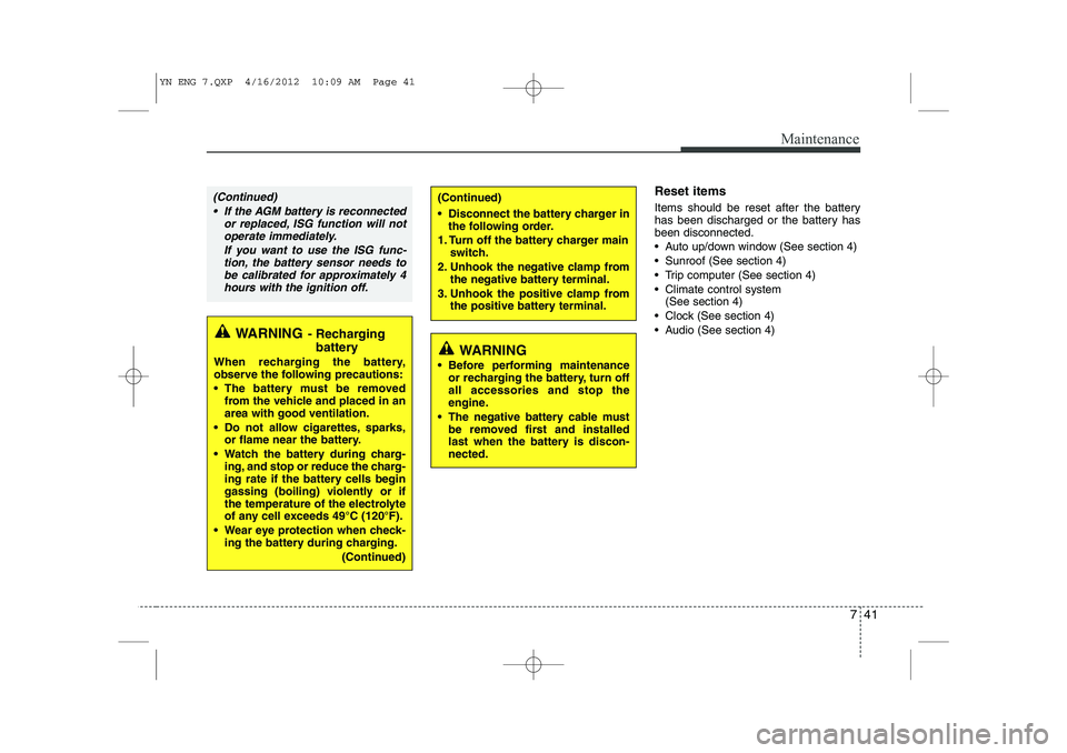
Reset items
Items should be reset after the battery
has been discharged or the battery hasbeen disconnected.
Auto up/down window (See section 4)
Sunroof (See section 4)
Trip computer (See section 4)
Climate control system (See section 4)
Clock (See section 4)
Audio (See section 4)
WARNING
Before performing maintenance or recharging the battery, turn off all accessories and stop the
engine.
The negative battery cable must be removed first and installed
last when the battery is discon-nected.
WARNING - Recharging
battery
When recharging the battery,
observe the following precautions:
The battery must be removed from the vehicle and placed in an area with good ventilation.
Do not allow cigarettes, sparks, or flame near the battery.
Watch the battery during charg- ing, and stop or reduce the charg-
ing rate if the battery cells begin
gassing (boiling) violently or if
the temperature of the electrolyte
of any cell exceeds 49°C (120°F).
Wear eye protection when check- ing the battery during charging.
(Continued)
(Continued)
Disconnect the battery charger inthe following order.
1. Turn off the battery charger main switch.
2. Unhook the negative clamp from the negative battery terminal.
3. Unhook the positive clamp from the positive battery terminal.(Continued)
If the AGM battery is reconnected or replaced, ISG function will notoperate immediately.
If you want to use the ISG func-tion, the battery sensor needs to be calibrated for approximately 4hours with the ignition off.
YN ENG 7.QXP 4/16/2012 10:09 AM Page 41
Page 351 of 751

Maintenance
58
7
DescriptionFuse ratingSystemProtected Component
15ATRANSMISSION
CONTROL UNITSpeed In Sensor, Speed Out Sensor, Speed Sensor, Inhibitor Switch
15AIGNITION COILIgnition Coil, Condensor
10AIGNITIONHLLD Switch, HLLD Actuator, BCM, Air Conditioning System, Sunroof
25AWINDSCREEN WIPING
SYSTEM (CONTINUOUS)Front Wiper Motor Relay, Multi Function Switch Wiper
10AFRONT FOG LAMPFront Fog Lamp, BCM
10AREAR FOG LAMPRear Fog Lamp, BCM
10AROOM LAMPRoom Lamp Switch, MUT
15ASTOP LAMPStop Switch, BCM
10ACLUSTERCluster, BCM, Digtal Clock
10AIGNITIONAudio,TPMS, Center Facia Switch
10AANTI-LOCK BRAKE SYSTEMYaw Rate Sensor, ABS(ESP),ESP Switch
10AB/UP LPBack Up Switch
10AELECTRONIC (ENGINE) CONTROL UNITECU, AFS
10ARAIN SENSOR
(PTC HEATER )Rain Sensor Relay (PTC, Fuel Filter Heater)
10APOWER DISTRIBUTION MODULESmart key Unit, SSB
YN ENG 7.QXP 4/16/2012 10:10 AM Page 58
Page 352 of 751
759
Maintenance
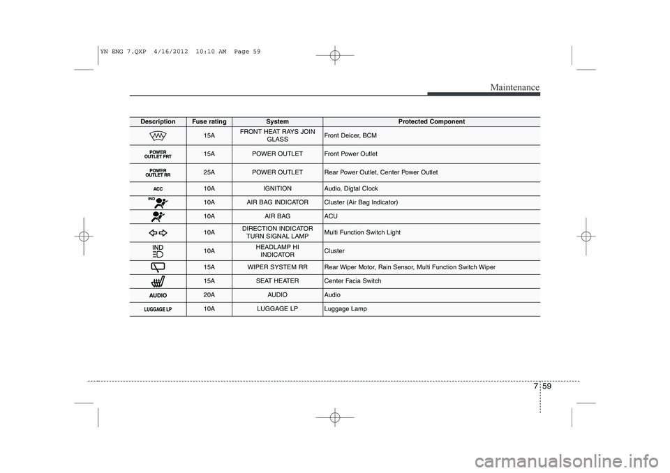
DescriptionFuse ratingSystemProtected Component
15AFRONT HEAT RAYS JOINGLASSFront Deicer, BCM
15APOWER OUTLETFront Power Outlet
25APOWER OUTLETRear Power Outlet, Center Power Outlet
10AIGNITIONAudio, Digtal Clock
10AAIR BAG INDICATORCluster (Air Bag Indicator)
10AAIR BAG ACU
10ADIRECTION INDICATORTURN SIGNAL LAMPMulti Function Switch Light
10AHEADLAMP HI INDICATORCluster
15AWIPER SYSTEM RRRear Wiper Motor, Rain Sensor, Multi Function Switch Wiper
15ASEAT HEATERCenter Facia Switch
20AAUDIOAudio
10ALUGGAGE LPLuggage Lamp
YN ENG 7.QXP 4/16/2012 10:10 AM Page 59
Page 353 of 751
Maintenance
60
7
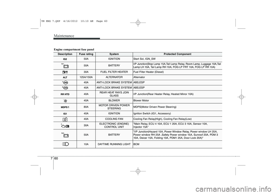
Engine compartment fuse panel
DescriptionFuse ratingSystemProtected Component
50AIGNITIONStart Sol, IGN_SW
50ABATTERYI/P Junction(Stop Lamp 15A,Tail Lamp Relay, Room Lamp, Luggage 10A,Tail
Lamp LH 10A, Tail Lamp RH 10A, FOG LP FRT 10A, FOG LP RR 10A)
30AFUEL FILTER HEATERFuel Filter Heater (Diesel)
125A/150AALTERNATORAlternator
40AANTI-LOCK BRAKE SYSTEMABS,ESP
40AANTI-LOCK BRAKE SYSTEMABS,ESP
40AREAR HEAT RAYS JOIN
GLASSI/P Junction(Rear Heater Relay, Heated Mirror 10A)
40ABLOWERBlower Motor
80AMOTOR DRIVEN POWERSTEERINGMDPS(Motor Driven Power Steering)
40AIGNITIONIgnition Switch (IG1, Accessory)
40ACOOLING FANCooling Fan Relay(High), Cooling Fan Relay(Low)
30AELECTRONIC (ENGINE)CONTROL UNIT"Main Relay, ECU 4 10A, ECU 1 20A, ECU 3 10A, Sensor 10A, Injector 15A"
50ABATTERY"I/P Junction(Hazard 15A, Power Window Relay, Power window LH 25A,
Power window RH 25A ,Safety Power window 15A, Sunroof 20A, PDM 3
10A, Deicer 15A, Folding 10A, PDM1 25A, Door Lock 20A)"
10ADAYTIME RUNNING LIGHTBCM
YN ENG 7.QXP 4/16/2012 10:10 AM Page 60
Page 354 of 751
761
Maintenance
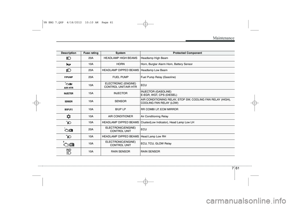
DescriptionFuse ratingSystemProtected Component
20AHEADLAMP HIGH BEAMSHeadlamp High Beam
10AHORNHorn, Burglar Alarm Horn, Battery Sensor
20AHEADLAMP DIPPED BEAMSHeadlamp Low Beam
F/PUMP20AFUEL PUMPFuel Pump Relay (Gasoline)
10AELECTRONIC (ENGINE)
CONTROL UNIT/AIR HTRECU
15AINJECTORINJECTOR (GASOLINE)
E-EGR, WGT, CPS (DIESEL)
10ASENSORAIR CONDITIONING RELAY, STOP SW, COOLING FAN RELAY (HIGH),
COOLING FAN RELAY (LOW)
10AB/UP LPRR COMBI LP, ECM MIRROR
10AAIR CONDITIONERAir Conditioning Relay
10AHEADLAMP DIPPED BEAMSCluster(Low Indicator), Head Lamp Low LH
20AELECTRONIC(ENGINE) CONTROL UNITECU
10AHEADLAMP DIPPED BEAMSHead Lamp Low RH
10AELECTRONIC(ENGINE) CONTROL UNITECU, TCU, GLOW Relay
10ARAIN SENSORRAIN SENSOR
YN ENG 7.QXP 4/16/2012 10:10 AM Page 61
Page 398 of 751
13
Introduction
Leaded (if equipped)
For some countries, your vehicle is
designed to use leaded petrol. When you
are going to use leaded petrol, we rec-
ommend that you ask to an authorised
Kia dealer. Octane Rating of leaded petrol is same
with unleaded one.
Petrol containing alcohol andmethanol
Gasohol, a mixture of petrol and ethanol
(also known as grain alcohol), and petrolor gasohol containing methanol (also
known as wood alcohol) are being mar-
keted along with or instead of leaded orunleaded petrol. Do not use gasohol containing more than 10% ethanol, and do not use petrol or
gasohol containing any methanol. Either
of these fuels may cause drivability prob-lems and damage to the fuel system.
Discontinue using gasohol of any kind if
drivability problems occur.
Vehicle damage or drivability problems
may not be covered by the manufacturer’s
warranty if they result from the use of: 1. Gasohol containing more than 10%
ethanol.
2. Petrol or gasohol containing methanol.
3. Leaded fuel or leaded gasohol.Use of MTBE
Kia recommends avoiding fuels contain-
ing MTBE (Methyl Tertiary Butyl Ether)
over 15.0% vol. (Oxygen Content 2.7%
weight) in your vehicle.
Fuel containing MTBE over 15.0% vol.
(Oxygen Content 2.7% weight) may
reduce vehicle performance and produce
vapour lock or hard starting.
Do not use methanol
Fuels containing methanol (wood alco-
hol) should not be used in your vehicle.
This type of fuel can reduce vehicle per-
formance and damage components ofthe fuel system.
WARNING
• Do not "top off" after the nozzle automatically shuts off when refueling.
Always check that the fuel cap is installed securely to prevent fuel
spillage in the event of an acci-dent.
CAUTION
NEVER USE LEADED FUEL. The
use of leaded fuel is detrimental to
the catalytic converter and willdamage the engine control sys-tem’s oxygen sensor and affect emission control.
Never add any fuel system cleaningagents to the fuel tank other thanwhat has been specified. (We rec-ommend that you consult an
authorised Kia.)
CAUTION
Never use gasohol which contains methanol. Discontinue use of anygasohol product which impairs dri-
vability.
YN RHD 1.QXP 3/31/2012 4:00 PM Page 3
Page 443 of 751
Safety features of your vehicle
38
3
How does the air bag system operate
Air bags are activated (able to inflate if
necessary) only when the ignition
switch is turned to the ON or STARTposition.
Air bags inflate instantly in the event of serious frontal or side collision (ifequipped with side impact air bag or
curtain air bag) in order to help protect
the occupants from serious physical
injury.
There is no single speed at which the air bags will inflate.
Generally, air bags are designed to
inflate based upon the severity of a col-
lision and its direction. These two fac-
tors determine whether the sensors
produce an electronic deployment/inflation signal.
Air bag deployment depends on a number of factors including vehiclespeed, angles of impact and the densi-
ty and stiffness of the vehicles or
objects which your vehicle hits in the
collision. The determining, factors are
not limited to those mentioned above.
The front air bags will completely inflate and deflate in an instant. It is virtually impossible for you to see
the air bags inflate during an accident.
It is much more likely that you will sim-ply see the deflated air bags hanging
out of their storage compartments afterthe collision.
In order to help provide protection in a severe collision, the air bags must
inflate rapidly. The speed of air bag
inflation is a consequence of extremely
short time in which a collision occursand the need to get the air bag
between the occupant and the vehicle
structures before the occupant impacts
those structures. This speed of inflation
reduces the risk of serious or life-
threatening injuries in a severe collision
and is thus a necessary part of air bagdesign.
However, air bag inflation can also
cause injuries which can include facial
abrasions, bruises and broken bonesbecause the inflation speed also caus-
es the air bags to expand with a great
deal of force.
There are even circumstances under which contact with the steer-
ing wheel air bag can cause fatal
injuries, especially if the occupant
is positioned excessively close tothe steering wheel.
WARNING
To avoid severe personal injury or death caused by deploying air
bags in a collision, the driver
should sit as far back from the
steering wheel air bag as possible
(at least 250 mm (10 inches)
away). The front passenger should
always move their seat as far
back as possible and sit back intheir seat.
Air bag inflates instantly in an event of a collision, passengers
may be injured by the air bag
expansion force if they are not in
a proper position.
Air bag inflation may cause injuries including facial or bodily
abrasions, injuries from broken
glasses or burns.
YN RHD 3.QXP 3/31/2012 4:03 PM Page 38
Page 447 of 751
Safety features of your vehicle
42
3
SRS components and functions
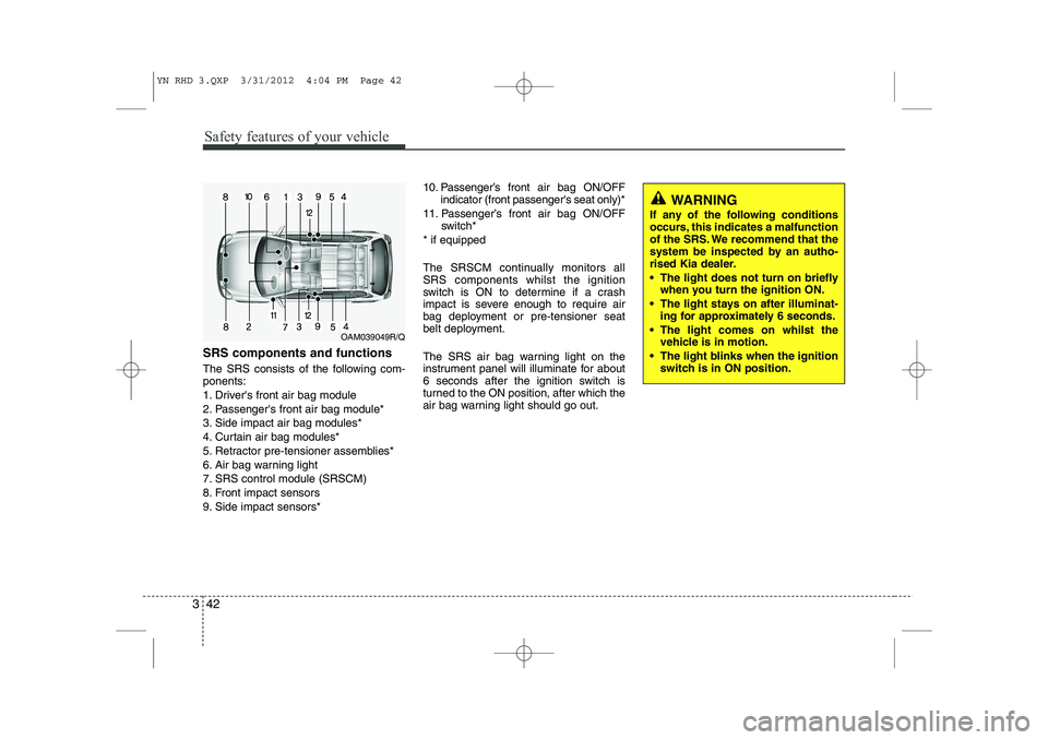
The SRS consists of the following com- ponents:
1. Driver's front air bag module
2. Passenger's front air bag module*
3. Side impact air bag modules*
4. Curtain air bag modules*
5. Retractor pre-tensioner assemblies*
6. Air bag warning light
7. SRS control module (SRSCM)
8. Front impact sensors
9. Side impact sensors* 10. Passenger’s front air bag ON/OFF
indicator (front passenger's seat only)*
11. Passenger’s front air bag ON/OFF switch*
* if equipped
The SRSCM continually monitors all SRS components whilst the ignition
switch is ON to determine if a crash
impact is severe enough to require air
bag deployment or pre-tensioner seat
belt deployment.
The SRS air bag warning light on the
instrument panel will illuminate for about
6 seconds after the ignition switch is
turned to the ON position, after which the
air bag warning light should go out.
WARNING
If any of the following conditions
occurs, this indicates a malfunction
of the SRS. We recommend that the
system be inspected by an autho-
rised Kia dealer.
The light does not turn on briefly when you turn the ignition ON.
The light stays on after illuminat- ing for approximately 6 seconds.
The light comes on whilst the vehicle is in motion.
The light blinks when the ignition switch is in ON position.
OAM039049R/Q
YN RHD 3.QXP 3/31/2012 4:04 PM Page 42
Page 455 of 751
Safety features of your vehicle
50
3
The side impact air bags are designed to
deploy only during certain side-impact
collisions, depending on the crash sever-
ity, angle, speed and point of impact. Theside impact air bags are not designed to
deploy in all side impact situations.(Continued)
Do not use any accessory seat
covers.
Use of seat covers could reduce or prevent the effectiveness of the system.
Do not install any accessories on the side or near the side impact
air bag.
Do not place any objects over the air bag or between the air bag
and yourself.
Do not place any objects (an umbrella, bag, etc.) between the
front door and the front seat.
Such objects may become dan-
gerous projectiles and cause
injury if the supplemental side
impact air bag inflates.
To prevent unexpected deploy- ment of the side impact air bag
that may result in personal injury,
avoid impact to the side impact
sensor when the ignition switchis on.
If seat or seat cover is damaged, we recommend that the system
be serviced by an authorised Kia
dealer.WARNING
Do not allow the passengers to lean their heads or bodies onto
doors, put their arms on the doors,
stretch their arms out of the win-
dow, or place objects between the
doors and passengers when theyare seated on seats equipped with
side and/or curtain air bags.
The side impact air bag is sup- plemental to the driver's and the
passenger's seat belt systems
and is not a substitute for them.
Therefore your seat belts must be
worn at all times whilst the vehi-
cle is in motion. The air bags
deploy only in certain side impact
conditions severe enough to
cause significant injury to the
vehicle occupants.
For best protection from the side impact air bag system and to
avoid being injured by the
deploying side impact air bag,
both front seat occupants shouldsit in an upright position with the
seat belt properly fastened. Thedriver's hands should be placedon the steering wheel at the 9:00
and 3:00 positions. The passen-
ger's arms and hands should beplaced on their laps. (Continued)
YN RHD 3.QXP 3/31/2012 4:04 PM Page 50