KIA VENGA 2013 Owners Manual
Manufacturer: KIA, Model Year: 2013, Model line: VENGA, Model: KIA VENGA 2013Pages: 751, PDF Size: 27.49 MB
Page 351 of 751

Maintenance
58
7
DescriptionFuse ratingSystemProtected Component
15ATRANSMISSION
CONTROL UNITSpeed In Sensor, Speed Out Sensor, Speed Sensor, Inhibitor Switch
15AIGNITION COILIgnition Coil, Condensor
10AIGNITIONHLLD Switch, HLLD Actuator, BCM, Air Conditioning System, Sunroof
25AWINDSCREEN WIPING
SYSTEM (CONTINUOUS)Front Wiper Motor Relay, Multi Function Switch Wiper
10AFRONT FOG LAMPFront Fog Lamp, BCM
10AREAR FOG LAMPRear Fog Lamp, BCM
10AROOM LAMPRoom Lamp Switch, MUT
15ASTOP LAMPStop Switch, BCM
10ACLUSTERCluster, BCM, Digtal Clock
10AIGNITIONAudio,TPMS, Center Facia Switch
10AANTI-LOCK BRAKE SYSTEMYaw Rate Sensor, ABS(ESP),ESP Switch
10AB/UP LPBack Up Switch
10AELECTRONIC (ENGINE) CONTROL UNITECU, AFS
10ARAIN SENSOR
(PTC HEATER )Rain Sensor Relay (PTC, Fuel Filter Heater)
10APOWER DISTRIBUTION MODULESmart key Unit, SSB
YN ENG 7.QXP 4/16/2012 10:10 AM Page 58
Page 352 of 751
759
Maintenance
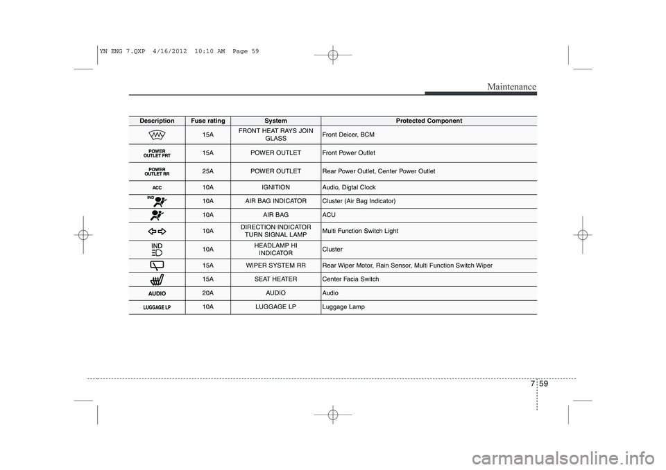
DescriptionFuse ratingSystemProtected Component
15AFRONT HEAT RAYS JOINGLASSFront Deicer, BCM
15APOWER OUTLETFront Power Outlet
25APOWER OUTLETRear Power Outlet, Center Power Outlet
10AIGNITIONAudio, Digtal Clock
10AAIR BAG INDICATORCluster (Air Bag Indicator)
10AAIR BAG ACU
10ADIRECTION INDICATORTURN SIGNAL LAMPMulti Function Switch Light
10AHEADLAMP HI INDICATORCluster
15AWIPER SYSTEM RRRear Wiper Motor, Rain Sensor, Multi Function Switch Wiper
15ASEAT HEATERCenter Facia Switch
20AAUDIOAudio
10ALUGGAGE LPLuggage Lamp
YN ENG 7.QXP 4/16/2012 10:10 AM Page 59
Page 353 of 751
Maintenance
60
7
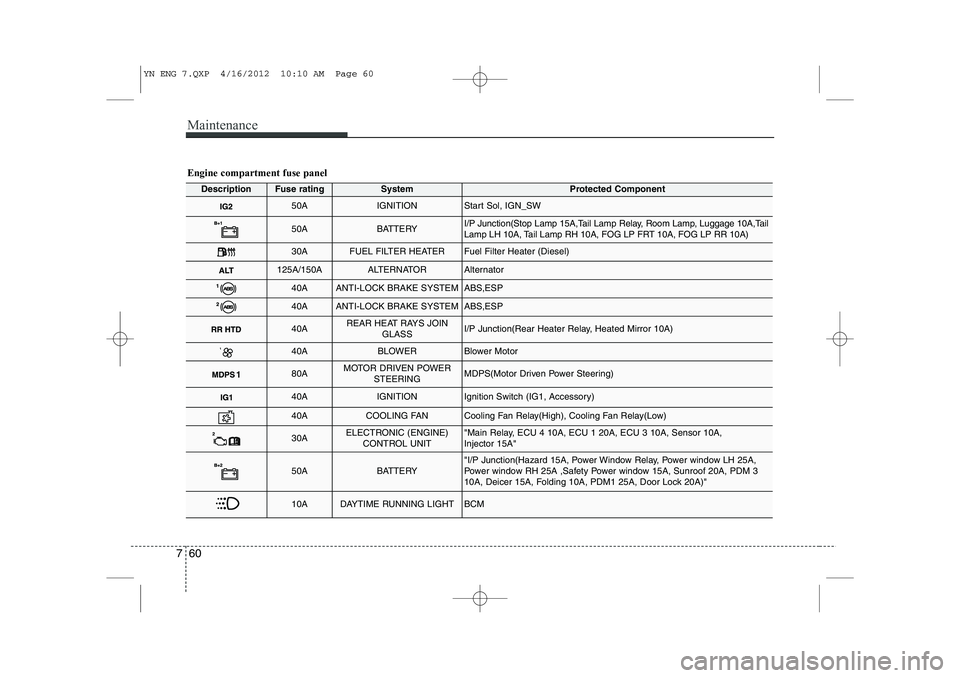
Engine compartment fuse panel
DescriptionFuse ratingSystemProtected Component
50AIGNITIONStart Sol, IGN_SW
50ABATTERYI/P Junction(Stop Lamp 15A,Tail Lamp Relay, Room Lamp, Luggage 10A,Tail
Lamp LH 10A, Tail Lamp RH 10A, FOG LP FRT 10A, FOG LP RR 10A)
30AFUEL FILTER HEATERFuel Filter Heater (Diesel)
125A/150AALTERNATORAlternator
40AANTI-LOCK BRAKE SYSTEMABS,ESP
40AANTI-LOCK BRAKE SYSTEMABS,ESP
40AREAR HEAT RAYS JOIN
GLASSI/P Junction(Rear Heater Relay, Heated Mirror 10A)
40ABLOWERBlower Motor
80AMOTOR DRIVEN POWERSTEERINGMDPS(Motor Driven Power Steering)
40AIGNITIONIgnition Switch (IG1, Accessory)
40ACOOLING FANCooling Fan Relay(High), Cooling Fan Relay(Low)
30AELECTRONIC (ENGINE)CONTROL UNIT"Main Relay, ECU 4 10A, ECU 1 20A, ECU 3 10A, Sensor 10A, Injector 15A"
50ABATTERY"I/P Junction(Hazard 15A, Power Window Relay, Power window LH 25A,
Power window RH 25A ,Safety Power window 15A, Sunroof 20A, PDM 3
10A, Deicer 15A, Folding 10A, PDM1 25A, Door Lock 20A)"
10ADAYTIME RUNNING LIGHTBCM
YN ENG 7.QXP 4/16/2012 10:10 AM Page 60
Page 354 of 751
761
Maintenance
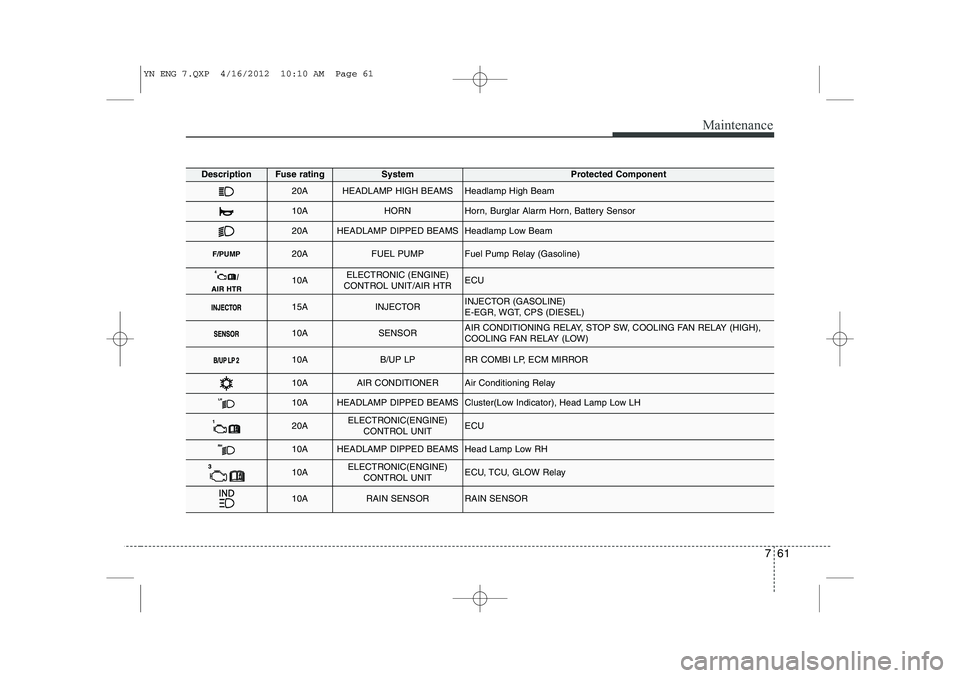
DescriptionFuse ratingSystemProtected Component
20AHEADLAMP HIGH BEAMSHeadlamp High Beam
10AHORNHorn, Burglar Alarm Horn, Battery Sensor
20AHEADLAMP DIPPED BEAMSHeadlamp Low Beam
F/PUMP20AFUEL PUMPFuel Pump Relay (Gasoline)
10AELECTRONIC (ENGINE)
CONTROL UNIT/AIR HTRECU
15AINJECTORINJECTOR (GASOLINE)
E-EGR, WGT, CPS (DIESEL)
10ASENSORAIR CONDITIONING RELAY, STOP SW, COOLING FAN RELAY (HIGH),
COOLING FAN RELAY (LOW)
10AB/UP LPRR COMBI LP, ECM MIRROR
10AAIR CONDITIONERAir Conditioning Relay
10AHEADLAMP DIPPED BEAMSCluster(Low Indicator), Head Lamp Low LH
20AELECTRONIC(ENGINE) CONTROL UNITECU
10AHEADLAMP DIPPED BEAMSHead Lamp Low RH
10AELECTRONIC(ENGINE) CONTROL UNITECU, TCU, GLOW Relay
10ARAIN SENSORRAIN SENSOR
YN ENG 7.QXP 4/16/2012 10:10 AM Page 61
Page 355 of 751
Maintenance
62
7
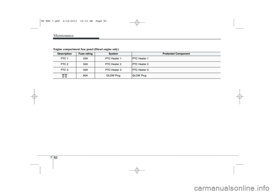
Engine compartment fuse panel (Diesel engine only)
DescriptionFuse ratingSystemProtected Component
PTC 150APTC Heater 1PTC Heater 1
PTC 250APTC Heater 2PTC Heater 2
PTC 350APTC Heater 3PTC Heater 3
80AGLOW PlugGLOW Plug
YN ENG 7.QXP 4/16/2012 10:10 AM Page 62
Page 356 of 751
763
Maintenance
LIGHT BULBS
Use only the bulbs of the specifiedwattage.
✽✽ NOTICE
After heavy, driving rain or washing, headlight and taillight lenses could
appear frosty. This condition is caused by
the temperature difference between the
lamp inside and outside. This is similar
to the condensation on your windows
inside your vehicle during the rain and
doesn’t indicate a problem with your
vehicle. If the water leaks into the lamp
bulb circuitry, we recommend that thesystem be checked by an authorized Kia
dealer.
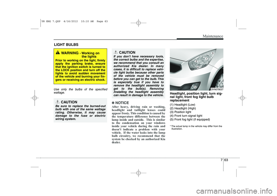
Headlight, position light, turn sig-
nal light, front fog light bulbreplacement
(1) Headlight (Low) (2) Headlight (High)
(3) Position light
(4) Front turn signal light
(5) Front fog light (if equipped)
* The actual lamp in the vehicle may differ from the illustration.
WARNING - Working on
the lights
Prior to working on the light, firmly
apply the parking brake, ensure
that the ignition switch is turned tothe LOCK position and turn off the
lights to avoid sudden movement
of the vehicle and burning your fin-
gers or receiving an electric shock.
CAUTION
Be sure to replace the burned-out bulb with one of the same wattagerating. Otherwise, it may cause
damage to the fuse or electricwiring system.
CAUTION
If you don’t have necessary tools,the correct bulbs and the expertise,
we recommend that you consult anauthorized Kia dealer. In many cases, it is difficult to replace vehi-cle light bulbs because other parts
of the vehicle must be removedbefore you can get to the bulb. This is especially true if you have to
remove the headlight assembly to
get to the bulb(s). Removing/installingthe headlight assembly
can result in damage to the vehicle.OYN079027
YN ENG 7.QXP 4/16/2012 10:10 AM Page 63
Page 357 of 751
Maintenance
64
7
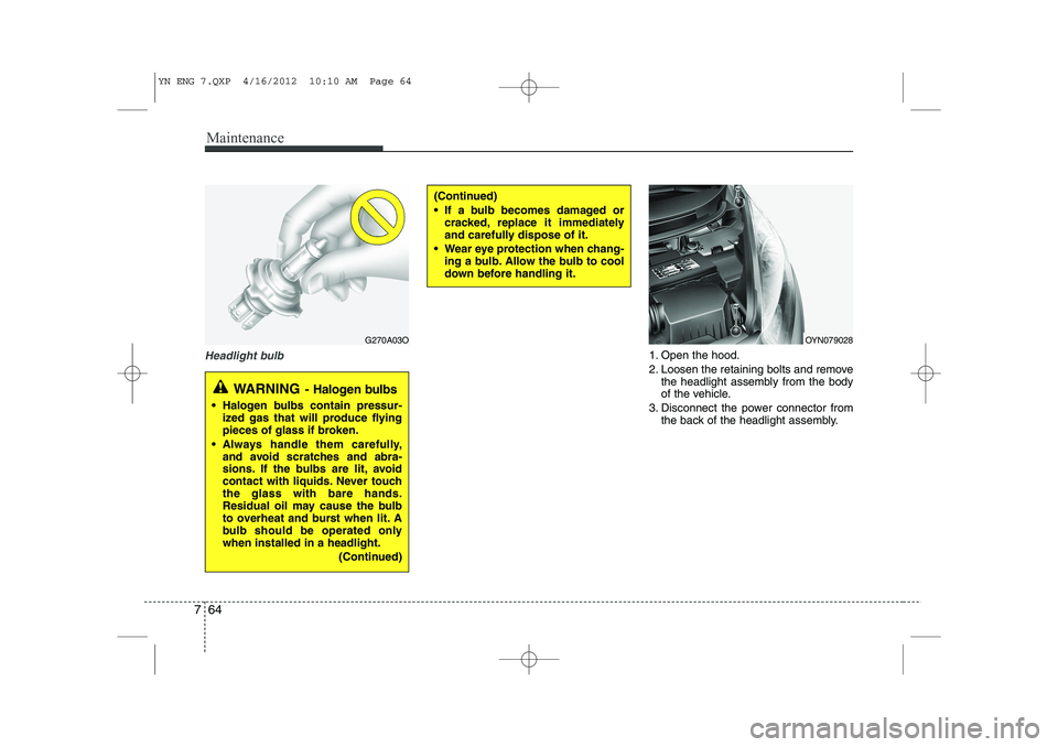
Headlight bulb1. Open the hood.
2. Loosen the retaining bolts and remove
the headlight assembly from the body
of the vehicle.
3. Disconnect the power connector from the back of the headlight assembly.
(Continued)
If a bulb becomes damaged orcracked, replace it immediately
and carefully dispose of it.
Wear eye protection when chang- ing a bulb. Allow the bulb to cool
down before handling it.
G270A03O
WARNING - Halogen bulbs
Halogen bulbs contain pressur-
ized gas that will produce flying
pieces of glass if broken.
Always handle them carefully, and avoid scratches and abra-
sions. If the bulbs are lit, avoid
contact with liquids. Never touchthe glass with bare hands.
Residual oil may cause the bulb
to overheat and burst when lit. A
bulb should be operated onlywhen installed in a headlight.
(Continued)
OYN079028
YN ENG 7.QXP 4/16/2012 10:10 AM Page 64
Page 358 of 751
765
Maintenance
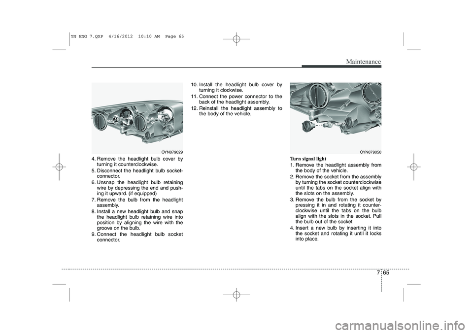
4. Remove the headlight bulb cover byturning it counterclockwise.
5. Disconnect the headlight bulb socket- connector.
6. Unsnap the headlight bulb retaining wire by depressing the end and push-
ing it upward. (if equipped)
7. Remove the bulb from the headlight assembly.
8. Install a new headlight bulb and snap the headlight bulb retaining wire into
position by aligning the wire with the
groove on the bulb.
9. Connect the headlight bulb socket connector. 10. Install the headlight bulb cover by
turning it clockwise.
11. Connect the power connector to the back of the headlight assembly.
12. Reinstall the headlight assembly to the body of the vehicle.
Turn signal light
1. Remove the headlight assembly fromthe body of the vehicle.
2. Remove the socket from the assembly by turning the socket counterclockwise
until the tabs on the socket align with
the slots on the assembly.
3. Remove the bulb from the socket by pressing it in and rotating it counter-
clockwise until the tabs on the bulb
align with the slots in the socket. Pull
the bulb out of the socket
4. Insert a new bulb by inserting it into the socket and rotating it until it locks
into place.
OYN079029OYN079050
YN ENG 7.QXP 4/16/2012 10:10 AM Page 65
Page 359 of 751
Maintenance
66
7
5. Install the socket in the assembly by
aligning the tabs on the socket with the
slots in the assembly. Push the socket
into the assembly and turn the socket
clockwise.
6. Reinstall the headlight assembly to the body of the vehicle.
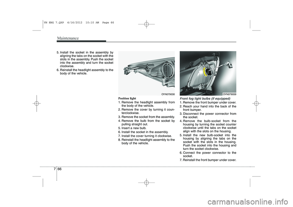
Position light
1. Remove the headlight assembly fromthe body of the vehicle.
2. Remove the cover by turning it coun- terclockwise.
3. Remove the socket from the assembly.
4. Remove the bulb from the socket by pulling straight out.
5. Insert a new bulb.
6. Install the socket in the assembly.
7. Install the cover turning it clockwise.
8. Reinstall the headlight assembly to the body of the vehicle.
Front fog light bulbs (if equipped)
1. Remove the front bumper under cover.
2. Reach your hand into the back of the
front bumper.
3. Disconnect the power connector from the socket.
4. Remove the bulb-socket from the housing by turning the socket counter
clockwise until the tabs on the socketalign with the slots on the housing.
5. Install the new bulb-socket into the housing by aligning the tabs on the
socket with the slots in the housing.
Push the socket into the housing and
turn the socket clockwise.
6. Connect the power connector to the socket.
7. Reinstall the front bumper under cover.
OYN079030OYN079059
YN ENG 7.QXP 4/16/2012 10:10 AM Page 66
Page 360 of 751
767
Maintenance
✽✽NOTICE
If the headlight aiming adjustment is
necessary after the headlight assembly is
reinstalled, we recommend that you con-
sult an authorized Kia dealer.
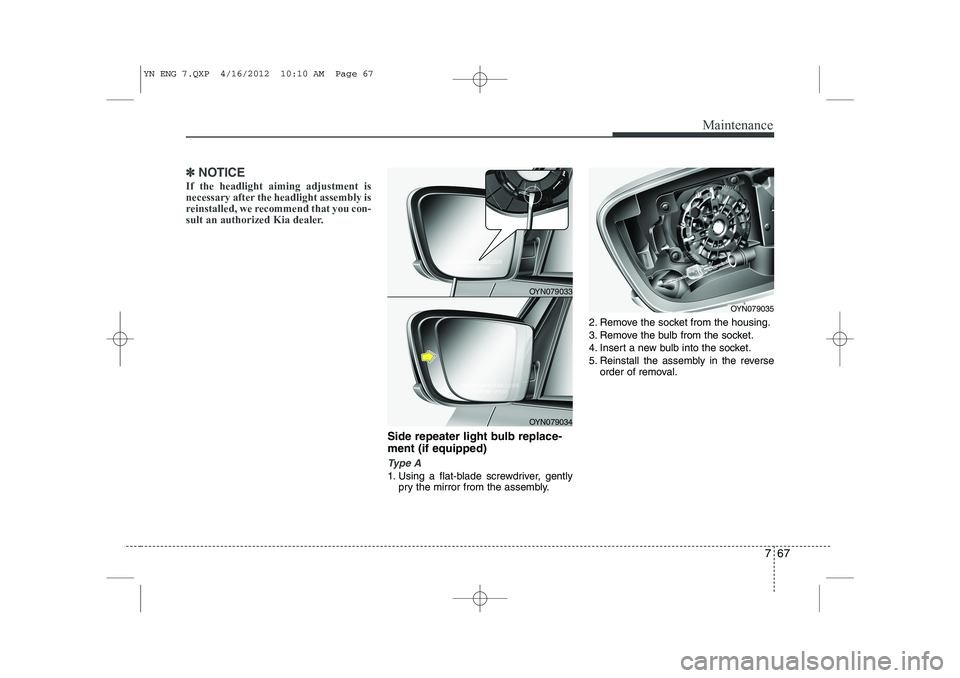
Side repeater light bulb replace- ment (if equipped)
Type A
1. Using a flat-blade screwdriver, gently pry the mirror from the assembly. 2. Remove the socket from the housing.
3. Remove the bulb from the socket.
4. Insert a new bulb into the socket.
5. Reinstall the assembly in the reverse
order of removal.
OYN079033
OYN079034
OYN079035
YN ENG 7.QXP 4/16/2012 10:10 AM Page 67