warning light Lancia Flavia 2013 Owner handbook (in English)
[x] Cancel search | Manufacturer: LANCIA, Model Year: 2013, Model line: Flavia, Model: Lancia Flavia 2013Pages: 244, PDF Size: 2.87 MB
Page 18 of 244
A WORD ABOUT YOUR
KEYSThe authorized dealer that sold you
your vehicle has the key code numbers
for your vehicle locks. These numbers
can be used to order duplicate keys
from your authorized dealer. Ask your
authorized dealer for these numbers
and keep them in a safe place.You can insert the double-sided keys
into the locks with either side up.
IGNITION KEY REMOVAL
Automatic Transaxle
Place the shift lever in PARK. Turn
the ignition switch to the ACC posi-
tion, push the key and cylinder in-
ward, rotate the key to the LOCK
position, and remove the key.NOTE:
If you try to remove the key be-
fore you place the shift lever in
PARK, the key may become
trapped temporarily in the igni-
tion switch lock cylinder. If this
occurs, rotate the key to the right
slightly, then remove the key as
described. If a malfunction oc-
curs, the system will trap the key
in the ignition switch lock cylin-
der to warn you that this safety
feature is inoperable. The en-
gine can be started and stopped,
but the key cannot be removed
until you obtain service.
The power window switches, radio,
hands-free system , and power out-
lets will remain active for up to
10 minutes after the ignition switch
is turned to the LOCK position.
Opening either front door will
cancel this feature. The time for
this feature is programmable. Re-
fer to “Electronic Vehicle Informa-
tion Center (EVIC)/Personal Set-
tings (Customer-Programmable
Features)” in “Understanding Your
Instrument Panel” for further in-
formation.WARNING!
Before exiting a vehicle, always
apply the parking brake, shift the
transmission into PARK, and
push ignition button to place ig-
nition in OFF position. When
leaving the vehicle, always lock
your vehicle.
Never leave children alone in a vehicle, or with access to an un-
locked vehicle.
(Continued)
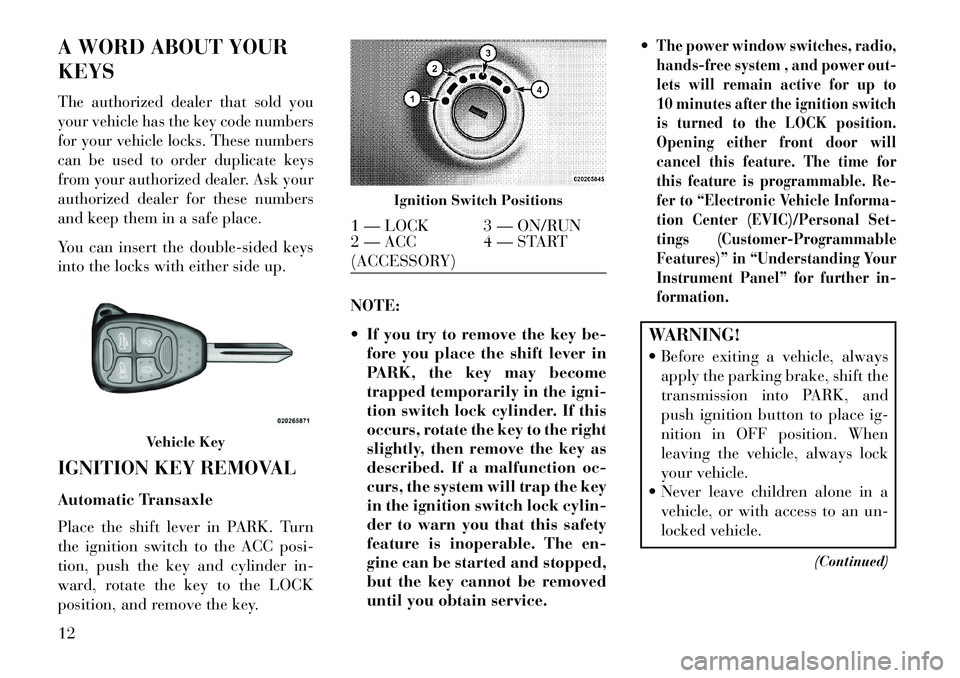
Vehicle Key
Ignition Switch Positions
1 — LOCK 3 — ON/RUN
2 — ACC
(ACCESSORY)4 — START
12
Page 26 of 244

NOTE:
If a fluttering noise is heard fromthe rear seat belts while driving
with the windows down, safely
bring the vehicle to a stop and
buckle the rear seat belts over
the empty seats. This will keep
tension on the seat belts and re-
move the fluttering condition.WARNING!Never leave children in a vehicle,
with the keys in the ignition switch.
Occupants, particularly unattended
children, can become entrapped by
the windows while operating the
power window switches. Such en-
trapment may result in serious in-
jury or death.Smart Glass Feature
The door window will lower slightly if
the window is fully up when opening
the door. The window will return to its
full up position after closing the door.
This action allows the door to open
without resistance and prevents win-
dow and top seal damage. Auto Window Down
The front window controls on the
driver and passenger door trim panels
have an Auto-Down feature. These
switches are labeled AUTO to indicate
this capability. Push the window
switch past the first detent, release,
and the window will go down auto-
matically.To open the window part way, push
the window switch to the first detent
and release it when you want the win-
dow to stop.
To cancel the Auto-Down movement,
operate the switch either in the up or
down direction and release the switch.The power window switches will remain
active for up to 10 minutes after the
ignition switch is turned to the LOCK
position. Opening either door will can-
cel this feature. The time for this feature
is programmable. Refer to “Electronic
Vehicle Information Center (EVIC)/
Personal Settings (Customer-Program-
mable Features)” in “Understanding
Your Instrument Panel” for further in-
formation.
Reset Window Smart Glass
Feature for Opening/Closing the
Door
If the vehicle battery goes dead, the
window Smart Glass Feature for
opening and closing the door will be
disabled. To reactivate the window
Smart Glass Feature, perform the fol-
lowing steps after vehicle power is
restored.
1. Lower all four windows to the full
open position.
2. Press and hold the Power Top
Switch in the Close direction. Once
the Power Top becomes fully closed,
all four windows will start closing.
3. Continue to hold the Power Top
Switch an additional two seconds
after the windows are fully closed.
4. Push all the window switches
down firmly to open the windows
completely and continue to hold the
switch down for an additional two
seconds after the window is fully
open.
20
Page 36 of 244

3.
Pull
downthenrearward to-
wards the rear of the vehicle then
down to engage the locking mecha-
nism. 4. The AHR front soft foam and trim
half should lock into the back decora-
tive plastic half.
NOTE:
If you have difficulties or prob-
lems resetting the Active Head
Restraints, see an authorized
dealer.
For safety reasons, have the Ac- tive Head Restraints checked by
a qualified specialist at an au-
thorized dealer. ENHANCED SEAT BELT
USE REMINDER SYSTEM
(BeltAlert®)
BeltAlert® is a feature intended to
remind the driver to fasten the seat
belt. The feature is active whenever
the ignition is on. If the driver is un-
belted, the Seat Belt Reminder Light
will turn on and remain on until the
seat belt is fastened.
The BeltAlert® warning sequence be-
gins after the vehicle speed is over
8 km/h, by blinking the Seat Belt
Reminder Light and sounding an in-
termittent chime. Once the sequence
starts, it will continue for the entire
duration or until the respective seat-
belt is fastened. After the sequence
completes, the Seat Belt Reminder
Light remains illuminated until the
respective seat belt is fastened. The
driver should instruct all other occu-
pants to fasten their seat belts. If the
driver's seat belt is unbuckled while
traveling at speeds greater than
8 km/h, BeltAlert® will provide both
audio and visual notification.
1 — Downward Movement
2 — Rearward Movement3 — Final Downward Movement To
Engage Locking Mechanism
AHR In Reset Position
30
Page 38 of 244
NOTE:
Air Bag covers may not be obvious
in the interior trim, but they will
open during air bag deployment. After any collision, the vehicleshould be taken to an autho-
rized dealer immediately.
Air Bag System ComponentsYour vehicle may be equipped with the
following air bag system components: Occupant Restraint Controller (ORC)
Air Bag Warning Light
Steering Wheel and Column
Instrument Panel
Knee Impact Bolster
Driver Advanced Front Air Bag
Passenger Advanced Front Air Bag
Supplemental Seat-Mounted Side Air Bags (SAB)
Front and Side Impact Sensors
Front Seat Belt Pretensioners, Seat Belt Buckle Switch Advanced Front Air Bag Features
The Advanced Front Air Bag system
has multistage driver and front pas-
senger air bags. This system provides
output appropriate to several factors,
including the severity and type of col-
lision as determined by the Occupant
Restraint Controller (ORC), which
may receive information from the
front impact sensors.
The first stage inflator is triggered
immediately during an impact that
requires air bag deployment. This low
output is used in less severe collisions.
A higher energy output is used for
more severe collisions.
WARNING!
No objects should be placed over or
near the air bag on the instrument
panel, because any such objects
could cause harm if the vehicle is in
a collision severe enough to cause
the air bag to inflate.
(Continued)
WARNING!
(Continued)
Do not put anything on or around
the air bag covers or attempt to
open them manually. You may
damage the air bags and you could
be injured because the air bags
may no longer be functional. The
protective covers for the air bag
cushions are designed to open only
when the air bags are inflating. Do not drill, cut or tamper with the knee bolster in any way.
Do not mount any accessories to
the knee bolster such as alarm
lights, stereos, citizen band radios,
etc.
Supplemental Seat-Mounted Side
Air Bags (SAB)
Supplemental Seat-Mounted Side Air
Bags (SAB) may provide enhanced
protection to help protect an occupant
during a side impact. The SAB is
marked with an air bag label sewn
into the outboard side of the front
seats.
32
Page 40 of 244

Air Bag Deployment Sensors
And ControlsOccupant Restraint Controller
(ORC)TheORC is part of a regulated safety
system required for this vehicle.
The ORC determines if deployment of
the front and/or side air bags in a
frontal or side collision is required.
Based on the impact sensor's signals,
a central electronic ORC deploys the
Advanced Front Air Bags, Supple-
mental Seat-Mounted Side Air Bags
(SAB), and front seat belt pretension-
ers, as required, depending on several
factors, including the severity and
type of impact.
Advanced Front Air Bags are designed
to provide additional protection by
supplementing the seat belts in cer-
tain frontal collisions depending on
several factors, including the severity
and type of collision. Advanced Front
Air Bags are not expected to reduce
the risk of injury in rear, side, or roll-
over collisions.
The Advanced Front Air Bags will not
deploy in all frontal collisions, includ-
ing some that may produce substantial
vehicle damage — for example, some
pole collisions, truck underrides, and
angle offset collisions. On the other
hand, depending on the type and loca-
tion of impact, Advanced Front Air
Bags may deploy in crashes with little
vehicle front-end damage but that
produce a severe initial deceleration.The side air bags will not deploy in all
side collisions. Side air bag deploy-
ment will depend on the severity and
type of collision.
Because air bag sensors measure ve-
hicle deceleration over time, vehicle
speed and damage by themselves are
not good indicators of whether or not
an air bag should have deployed.
Seat belts are necessary for your pro-
tection in all collisions, and also are
needed to help keep you in position,
away from an inflating air bag.
The ORC monitors the readiness of
the electronic parts of the air bag sys-
tem whenever the ignition switch is in
the START or ON/RUN position. If the key is in the OFF position, in the
ACC position, or not in the ignition,
the air bag system is not on and the air
bags will not inflate.
The ORC contains a backup power
supply system that may deploy the air
bags even if the battery loses power or
it becomes disconnected prior to
deployment.
Also, the ORC turns on the
Air Bag Warning Light in
the instrument panel for
approximately four to eight
seconds for a self-check when the ig-
nition is first turned on. After the self-
check, the Air Bag Warning Light will
turn off. If the ORC detects a mal-
function in any part of the system, it
turns on the Air Bag Warning Light,
either momentarily or continuously. A
single chime will sound if the light
comes on again after initial startup.
It also includes diagnostics that will
illuminate the instrument cluster Air
Bag Warning Light if a malfunction is
noted that could affect the air bag
system. The diagnostics also record
the nature of the malfunction.
34
Page 41 of 244
WARNING!
Ignoring the Air Bag Warning Light
in your instrument panel could
mean you won't have the air bags to
protect you in a collision. If the light
does not come on as a bulb check
when the ignition is first turned on,
stays on after you start the vehicle,
or if it comes on as you drive, have
an authorized dealer service the air
bag system immediately.
Driver And Passenger Advanced
Front Air Bag Inflator Units
The Driver and Passenger Advanced
Front Air Bag Inflator Units are lo-
cated in the center of the steering
wheel and on the right side of the
instrument panel. When the ORC de-
tects a collision requiring the Ad-
vanced Front Air Bags, it signals the
inflator units. A large quantity of non-
toxic gas is generated to inflate the
Advanced Front Air Bags. Different
air bag inflation rates are possible,
based on several factors, including the collision type and severity. The steer-
ing wheel hub trim cover and the up-
per right side of the instrument panel
separate and fold out of the way as the
air bags inflate to their full size. The
air bags fully inflate in about 50 to
70 milliseconds. This is about half of
the time it takes to blink your eyes.
The air bags then quickly deflate
while helping to restrain the driver
and front passenger.
The Advanced Front Air Bag gas is
vented through the vent holes in the
sides of the air bag. In this way, the air
bags do not interfere with your con-
trol of the vehicle.
Supplemental Seat-Mounted Side
Air Bag (SAB) Inflator Units
The Supplemental Seat-Mounted
Side Air Bags (SAB) are designed to
activate only in certain side collisions.
The ORC determines if a side collision
requires the side air bags to inflate,
based on the severity and type of col-
lision.Based on the severity and type of col-
lision, the side air bag inflator on the
crash side of the vehicle may be trig-
gered, releasing a quantity of non-
toxic gas. The inflating SAB exits
through the seat seam into the space
between the occupant and the door.
The SAB fully inflate in about 10 mil-
liseconds. The side air bag moves at a
very high speed and with such a high
force that it could injure you if you are
not seated properly, or if items are
positioned in the area where the side
air bag inflates. This especially ap-
plies to children.
Front And Side Impact Sensors
In front and side impacts, impact sen-
sors can aid the ORC in determining
appropriate response to impact
events.
35
Page 43 of 244
WARNING!
Deployed air bags and seat belt pre-
tensioners cannot protect you in
another collision. Have the air
bags, seat belt pretensioners, and
the front seat belt retractor assem-
blies replaced by an authorized
dealer immediately. Also, have the
Occupant Restraint Controller Sys-
tem serviced as well.
Maintaining Your Air Bag SystemWARNING!
Modifications to any part of the air bag system could cause it to
fail when you need it. You could
be injured if the air bag system is
not there to protect you. Do not
modify the components or wiring,
including adding any kind of
badges or stickers to the steering
wheel hub trim cover or the upper
right side of the instrument panel.
Do not modify the front bumper,
vehicle body structure, or add
aftermarket side steps or running
boards.
(Continued)
WARNING!(Continued)
It is dangerous to try to repair any part of the air bag system your-
self. Be sure to tell anyone who
works on your vehicle that it has
an air bag system.
Do not attempt to modify any part of your air bag system. The
air bag may inflate accidentally
or may not function properly if
modifications are made. Take
your vehicle to an authorized
dealer for any air bag system ser-
vice. If your seat, including your
trim cover and cushion, needs to
be serviced in any way (including
removal or loosening/tightening
of seat attachment bolts), take
the vehicle to your authorized
dealer. Only manufacturer ap-
proved seat accessories may be
used. If it is necessary to modify
the air bag system for persons
with disabilities, contact your au-
thorized dealer. Air Bag Warning Light
You will want to have the
air bags ready to inflate for
your protection in a colli-
sion. The Air Bag Warning
Light monitors the internal circuits
and interconnecting wiring associated
with air bag system electrical compo-
nents. While the air bag system is
designed to be maintenance free. If
any of the following occurs, have an
authorized dealer service the air bag
system immediately.
The Air Bag Warning Light does not come on during the four to eight
seconds when the ignition is first
cycled to the ON/RUN.
The Air Bag Warning Light remains on after the four to eight-second
interval.
The Air Bag Warning Light comes on intermittently or remains on
while driving.
37
Page 55 of 244

Air Bag Warning LightThe light should come on
and remain on for four to
eight seconds as a bulb
check when the ignition
switch is first turned ON. If the light is
not lit during starting, see your autho-
rized dealer. If the light stays on,
flickers, or comes on while driving,
have the system checked by an autho-
rized dealer.
Defroster
Check operation by selecting the de-
frost mode and place the blower con-
trol on high speed. You should be able
to feel the air directed against the
windshield. See your authorized
dealer for service if your defroster is
inoperable. Floor Mat Safety Information
Always use floor mats designed to fit
the footwell of your vehicle. Use only
floor mats that leave the pedal area
unobstructed and that are firmly se-
cured so that they cannot slip out of
position and interfere with the pedals
or impair safe operation of your ve-
hicle in other ways.
WARNING!
Pedals that cannot move freely can
cause loss of vehicle control and
increase the risk of serious personal
injury.
Always make sure that floor mats
are properly attached to the floor
mat fasteners.
Never place or install floor mats or other floor coverings in the ve-
hicle that cannot be properly se-
cured to prevent them from mov-
ing and interfering with the
pedals or the ability to control the
vehicle.
(Continued)
WARNING!(Continued)
Never put floor mats or other floor
coverings on top of already in-
stalled floor mats. Additional floor
mats and other coverings will re-
duce the size of the pedal area and
interfere with the pedals. Check mounting of mats on a regular basis. Always properly re-
install and secure floor mats that
have been removed for cleaning.
Always make sure that objects cannot fall into the driver foot-
well while the vehicle is moving.
Objects can become trapped un-
der the brake pedal and accelera-
tor pedal causing a loss of vehicle
control.
If required, mounting posts must be properly installed, if not
equipped from the factory.Failure to properly follow floor mat
installation or mounting can cause
interference with the brake pedal
and accelerator pedal operation
causing loss of control of the vehicle.
49
Page 72 of 244
CAUTION!To avoid damage to the mirror dur-
ing cleaning, never spray any clean-
ing solution directly onto the mirror.
Apply the solution onto a clean cloth
and wipe the mirror clean.OUTSIDE MIRRORS
To receive maximum benefit, adjust
the outside mirrors to center on the
adjacent lane of traffic and a slight
overlap of the view obtained from the
inside mirror.
NOTE: The passenger side con-
vex outside mirror will give a
much wider view to the rear, and
especially of the lane next to your
vehicle.
WARNING!
Vehicles and other objects seen in
the passenger side convex mirror
will look smaller and farther away
than they really are. Relying too
much on your passenger side con-
vex mirror could cause you to col-
lide with another vehicle or other
object. Use your inside mirror when
judging the size or distance of a
vehicle seen in the passenger side
convex mirror.
POWER MIRRORS
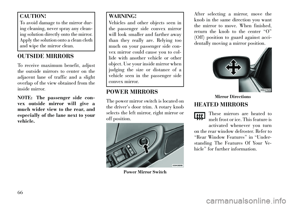
The power mirror switch is located on
the driver's door trim. A rotary knob
selects the left mirror, right mirror or
off position. After selecting a mirror, move the
knob in the same direction you want
the mirror to move. When finished,
return the knob to the center “O”
(Off) position to guard against acci-
dentally moving a mirror position.
HEATED MIRRORS
These mirrors are heated to
melt frost or ice. This feature is
activated whenever you turn
on the rear window defroster. Refer to
“Rear Window Features” in “Under-
standing The Features Of Your Ve-
hicle” for further information.
Power Mirror Switch
Mirror Directions
66
Page 81 of 244
After selecting one of the languages,
all prompts and voice commands will
be in that language.
NOTE:
After every Uconnect™
Phone language change operation,
only the language-specific 32-name
phonebook is usable. The paired
phone name is not language-specific
and is usable across all languages.
For command translations and alter-
nate commands in supported lan-
guages, refer to “Commands” in
“Voice Command System Operation”.Emergency Assistance (for
versions/markets, where provided)If you are in an emergency and the
mobile phone is reachable:
Pick up the phone and manually dial the emergency number for
your area. If the phone is not reachable and the
Uconnect™ Phone is operational, you
may reach the emergency number as
follows:
Press the
button to begin.
After the “Ready” prompt and the following beep, say “Emergency”
and the Uconnect™ Phone will in-
struct the paired mobile phone to
call the emergency number.
NOTE:
The default number is 112. The number dialed may not be ap-
plicable with the available mo-
bile service and area.
If supported, this number may be programmable on some sys-
tems. To do this, press the
button and say “Setup”, fol-
lowed by “Emergency”.
The Uconnect™ Phone does slightly lower your chances of
successfully making a phone
call as to that for the mobile
phone directly.
WARNING!
To use your Uconnect™ Phone Sys-
tem in an emergency, your mobile
phone must be:
turned on,
paired to the Uconnect™ System,
and have network coverage.Breakdown Service (for
versions/markets, where provided)If you need Breakdown service:
Press the
button to begin.
After the “Ready” prompt and the following beep, say “Breakdown
service”.
NOTE: The Breakdown service
number has to be setup before us-
ing. To setup, press the
button
and say “Setup, Breakdown Ser-
vice” and follow prompts.
75