ignition Lancia Musa 2008 Owner handbook (in English)
[x] Cancel search | Manufacturer: LANCIA, Model Year: 2008, Model line: Musa, Model: Lancia Musa 2008Pages: 218, PDF Size: 3.68 MB
Page 23 of 218
22
SAFETY
DEVICES
STARTING
AND
DRIVING
WARNING
LIGHTS AND
MESSAGES
IN AN
EMERGENCY
MAINTENANCE
AND CARE
TECHNICALSPECIFICATIONS
INDEX
DASHBOARD
AND CONTROLS
MULTIFUNCTIONAL
DISPLAY
(on two-line modal
panel)
The car can be equipped with a multi-
function display that shows useful in-
formation for car driving according to
the settings made. ENGINE COOLANT
TEMPERATURE GAUGE fig. 25
Warning light Aturns on to indicate
that the temperature of the engine
coolant has remarkably increased. In
this case, stop the engine and go to a
Lancia Dealership. This shows the tem-
perature of the engine coolant fluid and
starts working when the fluid temper-
ature exceeds approx. 50°C. In regular
operating conditions the needle moves
to the different positions allowed inside
the gauge according to the car operat-
ing conditions and management of the
engine cooling system.
IMPORTANT If the needle gets posi-
tioned at the beginning of the scale
(temperature low) and the warning
lightAis on, a failure has occurred in
the system. If this is the case, go to a
Lancia Dealership to have the system
checked.
If the needle indicating the
engine coolant temperature
reaches the red area, stop
the engine immediately and
contact a Lancia Dealership.
fig. 26L0D0027m
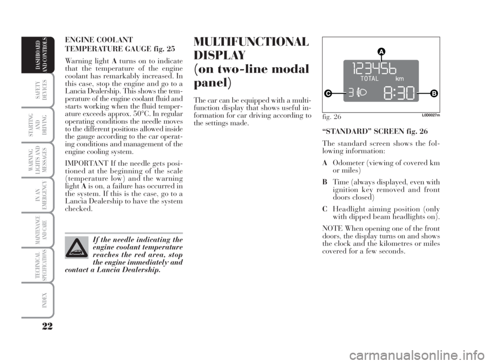
“STANDARD” SCREEN fig. 26
The standard screen shows the fol-
lowing information:
AOdometer (viewing of covered km
or miles)
BTime (always displayed, even with
ignition key removed and front
doors closed)
CHeadlight aiming position (only
with dipped beam headlights on).
NOTE When opening one of the front
doors, the display turns on and shows
the clock and the kilometres or miles
covered for a few seconds.
007-037 MUSA 3ed GB 12-11-2007 11:33 Pagina 22
Page 26 of 218
25
SAFETY
DEVICES
STARTING
AND
DRIVING
WARNING
LIGHTS AND
MESSAGES
IN AN
EMERGENCY
MAINTENANCE
AND CARE
TECHNICALSPECIFICATIONS
INDEX
DASHBOARD
AND CONTROLS
fig. 29L0D09000m
MULTIFUNCTIONAL
DISPLAY
(on three-line
comfort panel)
The car can be equipped with a mul-
tifunction display that shows useful
information for car driving according
to the settings made.
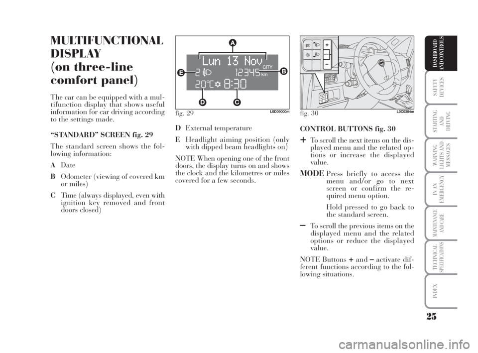
“STANDARD” SCREEN fig. 29
The standard screen shows the fol-
lowing information:
ADate
BOdometer (viewing of covered km
or miles)
CTime (always displayed, even with
ignition key removed and front
doors closed)CONTROL BUTTONS fig. 30
+To scroll the next items on the dis-
played menu and the related op-
tions or increase the displayed
value.
MODEPress briefly to access the
menu and/or go to next
screen or confirm the re-
quired menu option.
Hold pressed to go back to
the standard screen.
–To scroll the previous items on the
displayed menu and the related
options or reduce the displayed
value.
NOTE Buttons
+and–activate dif-
ferent functions according to the fol-
lowing situations. DExternal temperature
EHeadlight aiming position (only
with dipped beam headlights on)
NOTE When opening one of the front
doors, the display turns on and shows
the clock and the kilometres or miles
covered for a few seconds.
fig. 30L0C0384m
007-037 MUSA 3ed GB 12-11-2007 11:33 Pagina 25
Page 37 of 218
36
SAFETY
DEVICES
STARTING
AND
DRIVING
WARNING
LIGHTS AND
MESSAGES
IN AN
EMERGENCY
MAINTENANCE
AND CARE
TECHNICALSPECIFICATIONS
INDEX
DASHBOARD
AND CONTROLS
New mission
The new mission begins after:
– “manual” resetting by the user, by
pressing the relevant button;
– “automatic” resetting, when the
“Trip distance” reaches 9999.9 km or
when the “Travel time” reaches 99.59
(99 hours and 59 minutes);
– disconnection/reconnection of the
battery.
IMPORTANT The reset operations
performed after the “General Trip”
message appears are used to also re-
set the “Trip B”, which, on its turn, is
used to reset the values of the corre-
sponding function. Travel time
This value shows the time elapsed
since the start of a new mission.
IMPORTANT If information is not
available, the message “----” will ap-
pear instead of the Trip Computer
values. Displaying of the values will
be resumed regularly when normal
operation is restored without resetting
the values displayed before the failure
nor starting a new mission.
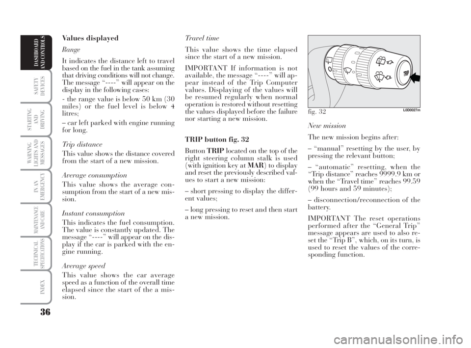
TRIP button fig. 32
ButtonTRIPlocated on the top of the
right steering column stalk is used
(with ignition key at MAR) to display
and reset the previously described val-
ues to start a new mission:
– short pressing to display the differ-
ent values;
– long pressing to reset and then start
a new mission. Values displayed
Range
It indicates the distance left to travel
based on the fuel in the tank assuming
that driving conditions will not change.
The message “----” will appear on the
display in the following cases:
- the range value is below 50 km (30
miles) or the fuel level is below 4
litres;
– car left parked with engine running
for long.
Trip distance
This value shows the distance covered
from the start of a new mission.
Average consumption
This value shows the average con-
sumption from the start of a new mis-
sion.
Instant consumption
This indicates the fuel consumption.
The value is constantly updated. The
message “----” will appear on the dis-
play if the car is parked with the en-
gine running.
Average speed
This value shows the car average
speed as a function of the overall time
elapsed since the start of the a mis-
sion.
fig. 32L0D0027m
007-037 MUSA 3ed GB 12-11-2007 11:33 Pagina 36
Page 38 of 218
37
SAFETY
DEVICES
STARTING
AND
DRIVING
WARNING
LIGHTS AND
MESSAGES
IN AN
EMERGENCY
MAINTENANCE
AND CARE
TECHNICALSPECIFICATIONS
INDEX
DASHBOARD
AND CONTROLS
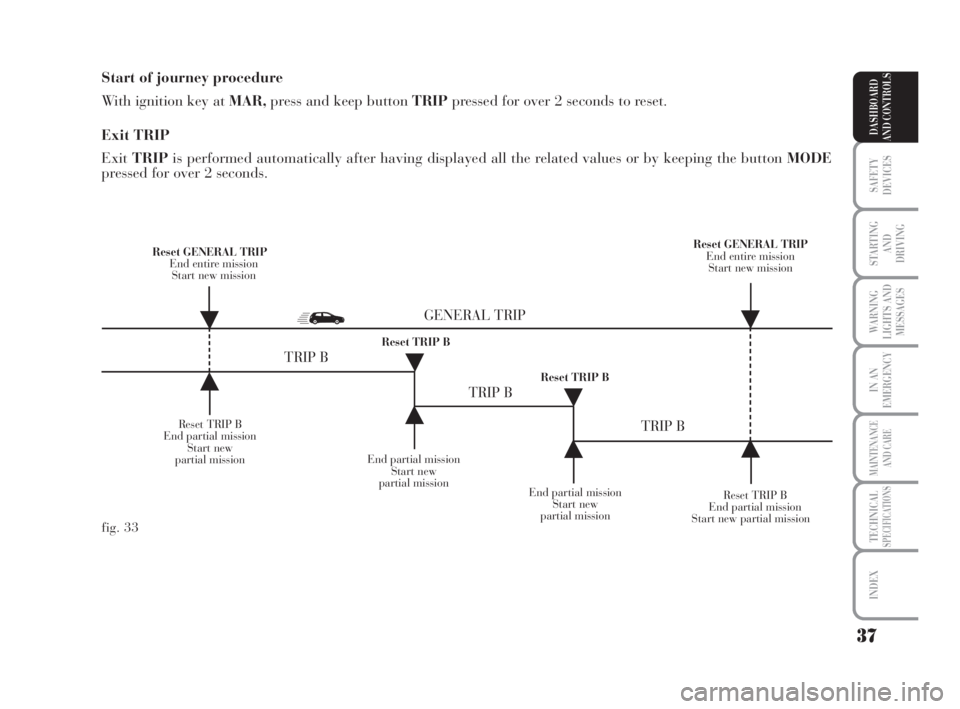
Start of journey procedure
With ignition key at MAR,press and keep button TRIPpressed for over 2 seconds to reset.
Exit TRIP
ExitTRIPis performed automatically after having displayed all the related values or by keeping the button MODE
pressed for over 2 seconds.
Reset TRIP B
End partial mission
Start new
partial missionEnd partial mission
Start new
partial mission
Reset TRIP B
End partial mission
Start new partial mission Reset GENERAL TRIP
End entire mission
Start new missionReset GENERAL TRIP
End entire mission
Start new mission
End partial mission
Start new
partial mission Reset TRIP B
Reset TRIP B
TRIP B
TRIP B
TRIP B GENERAL TRIP
˙
˙
˙
˙
˙
˙˙
˙
fig. 33
007-037 MUSA 3ed GB 12-11-2007 11:33 Pagina 37
Page 63 of 218
62
SAFETY
DEVICES
STARTING
AND
DRIVING
WARNING
LIGHTS AND
MESSAGES
IN AN
EMERGENCY
MAINTENANCE
AND CARE
TECHNICALSPECIFICATIONS
INDEX
DASHBOARD
AND CONTROLS
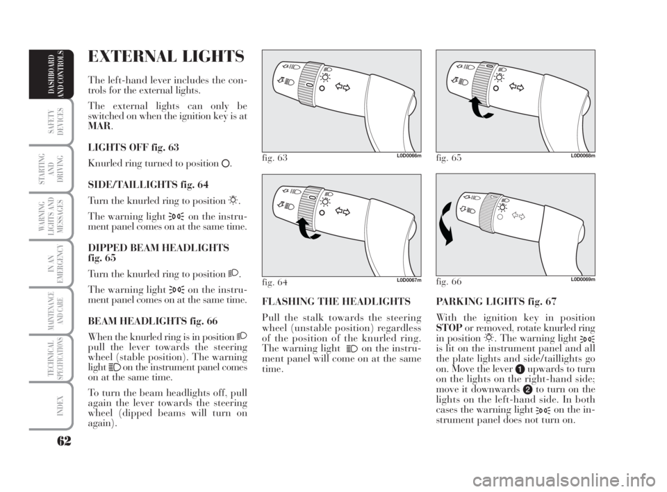
PARKING LIGHTS fig. 67
With the ignition key in position
STOPor removed, rotate knurled ring
in position
6. The warning light 3is lit on the instrument panel and all
the plate lights and side/taillights go
on. Move the lever
aupwards to turn
on the lights on the right-hand side;
move it downwards
bto turn on the
lights on the left-hand side. In both
cases the warning light
3on the in-
strument panel does not turn on. FLASHING THE HEADLIGHTS
Pull the stalk towards the steering
wheel (unstable position) regardless
of the position of the knurled ring.
The warning light
1on the instru-
ment panel will come on at the same
time.
fig. 63L0D0066m
fig. 66L0D0069m
fig. 65L0D0068m
fig. 64L0D0067m
EXTERNAL LIGHTS
The left-hand lever includes the con-
trols for the external lights.
The external lights can only be
switched on when the ignition key is at
MAR.
LIGHTS OFF fig. 63
Knurled ring turned to position
å.
SIDE/TAILLIGHTS fig. 64
Turn the knurled ring to position
6.
The warning light
3on the instru-
ment panel comes on at the same time.
DIPPED BEAM HEADLIGHTS
fig. 65
Turn the knurled ring to position
2.
The warning light
3on the instru-
ment panel comes on at the same time.
BEAM HEADLIGHTS fig. 66
When the knurled ring is in position
2pull the lever towards the steering
wheel (stable position). The warning
light
1on the instrument panel comes
on at the same time.
To turn the beam headlights off, pull
again the lever towards the steering
wheel (dipped beams will turn on
again).
038-094 MUSA 3ed GB 12-11-2007 11:35 Pagina 62
Page 64 of 218
63
SAFETY
DEVICES
STARTING
AND
DRIVING
WARNING
LIGHTS AND
MESSAGES
IN AN
EMERGENCY
MAINTENANCE
AND CARE
TECHNICALSPECIFICATIONS
INDEX
DASHBOARD
AND CONTROLS
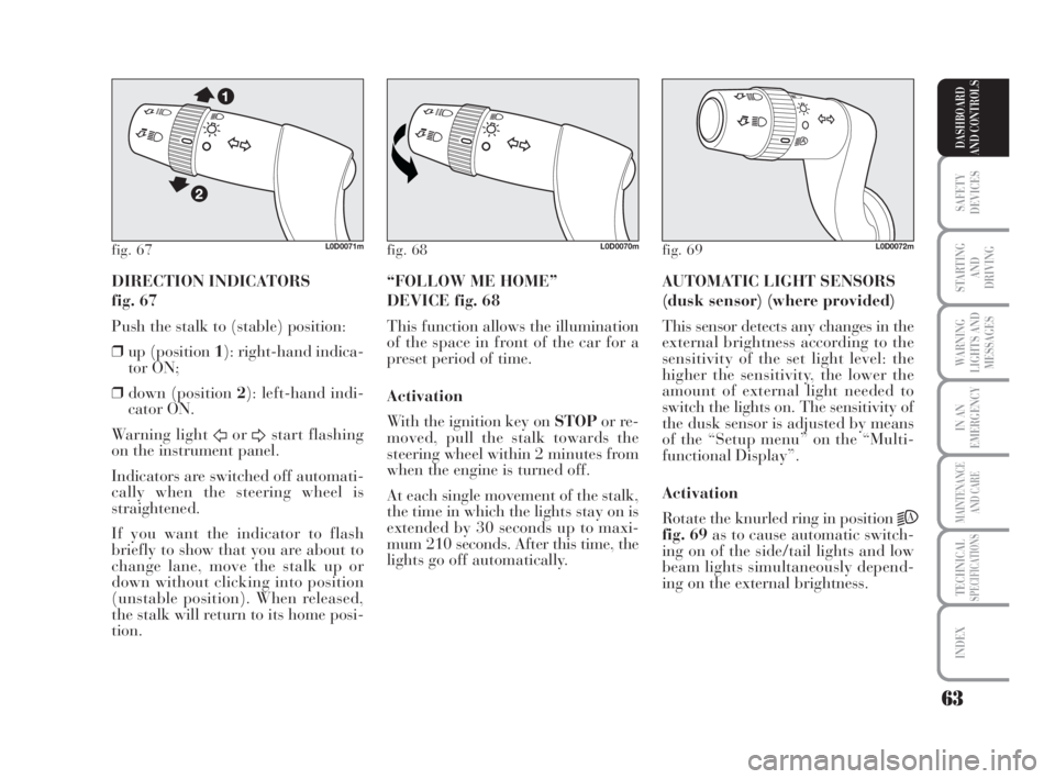
DIRECTION INDICATORS
fig. 67
Push the stalk to (stable) position:
❒up (position 1): right-hand indica-
tor ON;
❒down (position 2): left-hand indi-
cator ON.
Warning light
ForDstart flashing
on the instrument panel.
Indicators are switched off automati-
cally when the steering wheel is
straightened.
If you want the indicator to flash
briefly to show that you are about to
change lane, move the stalk up or
down without clicking into position
(unstable position). When released,
the stalk will return to its home posi-
tion.AUTOMATIC LIGHT SENSORS
(dusk sensor) (where provided)
This sensor detects any changes in the
external brightness according to the
sensitivity of the set light level: the
higher the sensitivity, the lower the
amount of external light needed to
switch the lights on. The sensitivity of
the dusk sensor is adjusted by means
of the “Setup menu” on the “Multi-
functional Display”.
Activation
Rotate the knurled ring in position
2A
fig. 69as to cause automatic switch-
ing on of the side/tail lights and low
beam lights simultaneously depend-
ing on the external brightness. “FOLLOW ME HOME”
DEVICE fig. 68
This function allows the illumination
of the space in front of the car for a
preset period of time.
Activation
With the ignition key on STOPor re-
moved, pull the stalk towards the
steering wheel within 2 minutes from
when the engine is turned off.
At each single movement of the stalk,
the time in which the lights stay on is
extended by 30 seconds up to maxi-
mum 210 seconds. After this time, the
lights go off automatically.
fig. 67L0D0071mfig. 68L0D0070mfig. 69L0D0072m
038-094 MUSA 3ed GB 12-11-2007 11:35 Pagina 63
Page 65 of 218

64
SAFETY
DEVICES
STARTING
AND
DRIVING
WARNING
LIGHTS AND
MESSAGES
IN AN
EMERGENCY
MAINTENANCE
AND CARE
TECHNICALSPECIFICATIONS
INDEX
DASHBOARD
AND CONTROLS
WINDOW
WASHING
WINDSCREEN
WASHER/WIPER
The device can work only when the
ignition key is on MAR.
The right lever can take five different
positions:
Awindscreen wiper off
Bintermittent.
With the lever in position B, turn the
knurled ring Fto select one of four
different speeds for the intermittent
operation mode:
,= very slow intermittence
--= slow intermittence
---= mean intermittence
----= fast intermittence When the automatic light sensor is ac-
tivated, the multifunctional display
shows the pre-set sensor sensitivity
level. On this screen it is possible to
adjust the sensitivity level using the
buttons
+and–(seefig. 70).
Deactivation
The main beam headlights will go out
followed by the side/tail lights after
approximately 10 seconds, when the
sensor is deactivated.
If the beam headlights are enabled
(manually by the driver) during au-
tomatic lighting, the beam lights go
off automatically along with the
lights.
IMPORTANT The sensor cannot de-
tect the presence of fog. So, in foggy
conditions, switch the lights on man-
ually.
fig. 70L0D0384m
fig. 71L0C0073m
Ccontinuous slow operation;
Dcontinuous fast operation
Etemporary fast operation
(unstable position).
038-094 MUSA 3ed GB 12-11-2007 11:35 Pagina 64
Page 67 of 218

66
SAFETY
DEVICES
STARTING
AND
DRIVING
WARNING
LIGHTS AND
MESSAGES
IN AN
EMERGENCY
MAINTENANCE
AND CARE
TECHNICALSPECIFICATIONS
INDEX
DASHBOARD
AND CONTROLS
With windscreen wiper on and reverse
gear engaged, rear window wiping
will be continuous.
Pushing the stalk towards the dash-
board (unstable position) will activate
the rear window washer.
Keeping the stalk pushed for over half
a second will activate also the rear
window wiper.
Releasing the stalk will activate the
smart washing function as described
for the windscreen wiper. The sensor reactivation is signalled by
a windscreen wiper “stroke”.
The rain sensor is able to recognize
and automatically adjust itself in the
presence of the following particular
conditions:
❒impurities on the controlled sur-
face (salt, dirt, etc.);
❒difference between day and night.
Deactivation
Change the stalk knurled ring posi-
tion from Bor turn the ignition key to
STOP.
At the next start-up (key at MAR),
the sensor will not be reactivated even
if the stalk is at B. To activate the sen-
sor, move the stalk to position AorC
and then to position Bor turn the sen-
sitivity adjustment knurled ring.
fig. 73L0C0073m
Streaks of water may
cause unnecessary blade
moving.
WARNING
REAR WINDOW WASHER/
WIPER fig. 74
The device can work only when the
ignition key is on MAR.
Turning the knurled ring Afrom po-
sition
åto position 'will operate the
rear window wiper as follows:
❒intermittent operation if the
windscreen wiper is off;
❒synchronised with the windscreen
wiper (but with half stroke fre-
quency);
fig. 74L0D0075m
038-094 MUSA 3ed GB 12-11-2007 11:35 Pagina 66
Page 69 of 218
68
SAFETY
DEVICES
STARTING
AND
DRIVING
WARNING
LIGHTS AND
MESSAGES
IN AN
EMERGENCY
MAINTENANCE
AND CARE
TECHNICALSPECIFICATIONS
INDEX
DASHBOARD
AND CONTROLS
DEVICE DISENGAGEMENT
Turn the knurled ring A-fig. 75to
OFFor the ignition key to STOP. In
addition, the device is automatically
disengaged in one of the following
cases:
❒pressing the brake pedal. TO REDUCE MEMORISED
SPEED
The stored speed can be increased in
two ways:
❒disengaging the device and then
memorising the new speed;
or
❒moving the stalk downwards (
–)
until reaching the new speed which
will be memorised automatically.
Each operation of the stalk will cor-
respond to a slight reduction in speed
(about 1 km/h), while keeping the
stalk downwards will correspond to a
continuous speed reduction. RESTORING STORED SPEED
If the device has been disengaged for
example pressing the brake or clutch
pedal, the memorised speed can be re-
set as follows:
❒accelerate gradually until reaching
a speed approaching the one
memorised;
❒engage the gear selected at the
time of speed memorising (4thor
5thgear);
❒press the button RES B.
TO INCREASE THE
MEMORISED SPEED
The stored speed can be increased
in two ways:
❒pressing the accelerator and then
memorising the new speed
reached;
or
❒moving the stalk upwards (
+).
Each operation of the stalk will cor-
respond to a slight increase in speed
(about 1 km/h), while keeping the
stalk upwards will correspond to a
continuous speed increase.
While travelling with the
device engaged, do not set
the gearshift lever to neutral.
WARNING
In case of malfunctioning
or fault of the device, turn
the knurled ring to OFF and con-
tact the Lancia Dealership, after
checking that the protection fuse is
not blown.
WARNING
038-094 MUSA 3ed GB 12-11-2007 11:35 Pagina 68
Page 76 of 218
75
SAFETY
DEVICES
STARTING
AND
DRIVING
WARNING
LIGHTS AND
MESSAGES
IN AN
EMERGENCY
MAINTENANCE
AND CARE
TECHNICALSPECIFICATIONS
INDEX
DASHBOARD
AND CONTROLS
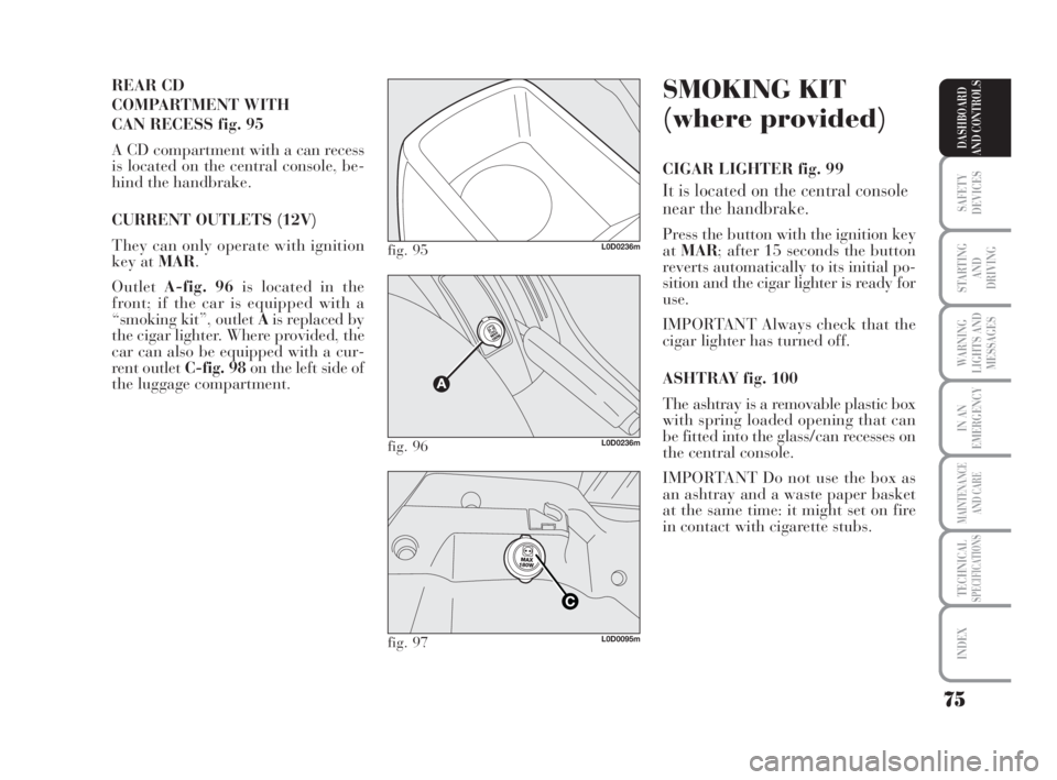
REAR CD
COMPARTMENT WITH
CAN RECESS fig. 95
A CD compartment with a can recess
is located on the central console, be-
hind the handbrake.
CURRENT OUTLETS (12V)
They can only operate with ignition
key at MAR.
OutletA-fig. 96is located in the
front; if the car is equipped with a
“smoking kit”, outlet Ais replaced by
the cigar lighter. Where provided, the
car can also be equipped with a cur-
rent outlet C-fig. 98on the left side of
the luggage compartment.
fig. 95L0D0236m
fig. 96L0D0236m
fig. 97L0D0095m
SMOKING KIT
(where provided)
CIGAR LIGHTER fig. 99
It is located on the central console
near the handbrake.
Press the button with the ignition key
atMAR; after 15 seconds the button
reverts automatically to its initial po-
sition and the cigar lighter is ready for
use.
IMPORTANT Always check that the
cigar lighter has turned off.
ASHTRAY fig. 100
The ashtray is a removable plastic box
with spring loaded opening that can
be fitted into the glass/can recesses on
the central console.
IMPORTANT Do not use the box as
an ashtray and a waste paper basket
at the same time: it might set on fire
in contact with cigarette stubs.
038-094 MUSA 3ed GB 12-11-2007 11:35 Pagina 75